am series pulse boiler troubleshooting guide - Agencespl.com
am series pulse boiler troubleshooting guide - Agencespl.com
am series pulse boiler troubleshooting guide - Agencespl.com

You also want an ePaper? Increase the reach of your titles
YUMPU automatically turns print PDFs into web optimized ePapers that Google loves.
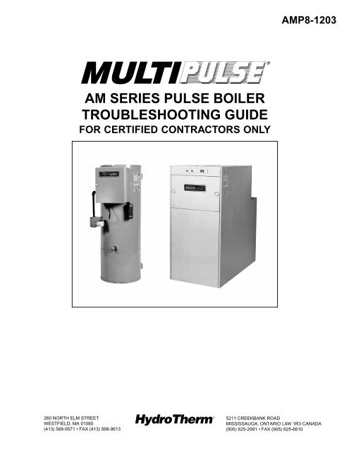
AMP8-1203<br />
®<br />
AM SERIES PULSE BOILER<br />
TROUBLESHOOTING GUIDE<br />
FOR CERTIFIED CONTRACTORS ONLY<br />
260 NORTH ELM STREET<br />
WESTFIELD, MA 01085<br />
(413) 568-9571 • FAX (413) 568-9613<br />
5211 CREEKBANK ROAD<br />
MISSISSAUGA, ONTARIO L4W 1R3 CANADA<br />
(905) 625-2991 • FAX (905) 625-6610
TABLE OF CONTENTS<br />
SECTION 1: OPERATION<br />
Boiler Operating Lights - Location and function ..................................................................................................3<br />
Sequence of Operation (with lights) ...................................................................................................................3<br />
Wiring Diagr<strong>am</strong>s (AM-100/-150/-300) ................................................................................................................ 5<br />
Lighting and Operating Instructions ................................................................................................................... 8<br />
SECTION 2: TROUBLE SHOOTING<br />
Preliminary Operational Check ...........................................................................................................................9<br />
- Boiler is not running:<br />
Condition GC-4A Light Red Light Amber Light<br />
A Off Off Off ....................................9<br />
B Off Off On ..................................10<br />
C Off On ...................................................................11<br />
D On ...................................................................................................12<br />
E Blinking ...............................................................................................13<br />
- Boiler is running:<br />
Condition 1. Boiler ignites: runs for 8 seconds then shuts off .......................................................15<br />
Condition 2. Boiler attempts ignition (8 seconds) - shuts off with a “cough” or no ignition ............16<br />
Condition 3. Boiler is “short cycling” ..............................................................................................19<br />
Condition 4. Boiler and condensate water leaks ...........................................................................22<br />
Condition 5. Boiler noise (control and adjustment) .......................................................................24<br />
a) Prolonged stutter on start-up .......................................................................................25<br />
b) Combustion/operating noise ........................................................................................26<br />
c) Vibration noise .............................................................................................................27<br />
d) Objectionable exhaust noise ........................................................................................27<br />
e) Objectionable (localized) ..............................................................................................28<br />
SECTION 3: SERVICING/REPAIR PROCEDURES<br />
Service Tools List .............................................................................................................................................29<br />
Fan Pressure Check .........................................................................................................................................29<br />
Gas Supply Pressure Check ............................................................................................................................29<br />
Gas Input Rate Check (Metered and Differential Methods) ..............................................................................30<br />
Adjusting Input Rate .........................................................................................................................................30<br />
Flue Box Adaptor Repair (AM-300) ..................................................................................................................30<br />
Fan Inlet Gasket Replacement (AM-300) .........................................................................................................31<br />
Air Inlet Orifice Repair (AM-300) ......................................................................................................................31<br />
Igntion Wire Check ...........................................................................................................................................31<br />
Wire Harness Assembly Replacement (AM-100 and 150) ...............................................................................31<br />
Exhaust Cushion Ch<strong>am</strong>ber (ECC) and/or “O” Ring Replacement (AM-100 and 150) ......................................33<br />
Disassembling AM-300 Boiler ......................................................................................................................... 33<br />
Leak Check (AM-300) .......................................................................................................................................35<br />
-Reassembly AM-300 Boiler ......................................................................................................................35<br />
-Reposition Boiler in it's location (AM-300) ................................................................................................36<br />
Heat Exchanger Replacement (AM-100 and 150) ............................................................................................37<br />
Boiler Reassembly (AM-100 and 150) ..............................................................................................................37<br />
Quick-Check Trouble Shooting Guide – GC-4A ...............................................................................................39<br />
SECTION 4: REPLACEMENT PARTS LIST<br />
Part Identification/Figs. 9 thru 12 (AM-100 / -150 / -300) .................................................................................40<br />
2
SECTION 1: OPERATION<br />
BOILER OPERATING LIGHTS<br />
AMBER<br />
LIGHT<br />
RED<br />
LIGHT<br />
Part of 115V ON-OFF rocker switch<br />
(SW1). Side of electric box (AM-100 and<br />
AM-150). Front top of <strong>boiler</strong> (AM-300). Lit<br />
when switch is on.<br />
Top of electric box (AM-100 and AM-150).<br />
Front top of <strong>boiler</strong> (AM-300). Lit when<br />
all operational controls are calling for heat<br />
and 24V is supplied to the GC-4A ignition<br />
control.<br />
GREEN Top of electric box (AM-100 and 150).<br />
LIGHT Front top of <strong>boiler</strong> (AM-300). Lit when<br />
gas valve is energized (24V).<br />
GC-4A<br />
LIGHT<br />
LAMP<br />
CHECK<br />
On GC-4A ignition control - visible thru a<br />
cutout in control cover near the 6-pin<br />
Molex connector. OFF when no 24V to<br />
control (no call for heat). Lit when <strong>boiler</strong> is<br />
running, GC-4A is in ignition sequence or on<br />
“hold” - refer to operating sequence.<br />
“Blinking” when GC-4A is in “lockout” or in<br />
the middle of a retrial period.<br />
Red and green bulbs can be checked with<br />
Volt/ohm meter: disconnect the l<strong>am</strong>p from<br />
the circuit and check across the leads for<br />
continuity. Replace any burned out lights<br />
or loose wiring.<br />
SEQUENCE OF OPERATION (WITH LIGHTS)<br />
1. Gas On/Power On. With Rocker switch SW1 (On/Off<br />
switch) closed (<strong>am</strong>ber light is ON) 115/24V<br />
transformer is powered. Refer to figure 1, 2 or 3<br />
for <strong>boiler</strong> wiring diagr<strong>am</strong>s.<br />
2. Boiler thermostat calls for heat; “T-T” contacts CLOSE;<br />
and circulator relay R1 (AM-100 and AM-150 only)<br />
is energized. The circulator relay contacts<br />
(C1R1) close starting the circulator pump<br />
(AM-100/-150).<br />
3. 24 volts is also supplied to the high limit. If the<br />
limit (automatic reset type) is “OPEN” (Red Light<br />
OFF) due to high water temperature, the ignition<br />
control waits until limit closes. When the limit closes<br />
(Red Light ON), the GC-4A ignition control is<br />
energized (GC-4A Light ON) and checks the<br />
position of the Combustion Prove Switch (PS1)<br />
contacts (N.O.- NORMALLY OPEN). On AM-150,<br />
the blocked inlet switch (PS3) contacts<br />
(N.C.-NORMALLY CLOSED) are also checked. If<br />
the (PS1) contacts are OPEN and the (PS3) contacts<br />
(AM-150 only) are “CLOSED”, the GC-4A control<br />
will begin the timed ignition sequence. If either or<br />
both of the pressure switch contacts is in an incorrect<br />
position, the GC-4A goes on “HOLD” (Red Light<br />
“ON”; GC-4A Light “ON”) unti switch position is<br />
corrected.<br />
4. With the above condition satisfied, the GC-4A<br />
control will begin a timed pre-purge sequence<br />
(35-seconds); start the fan; and check the fan<br />
Prove Switch (PS2) contact position. This switch<br />
contact (N.O.), must close proving blower operation<br />
before any gas ignition will occur. If the Fan Prove<br />
Switch (PS2) contacts are “CLOSED” after the<br />
initial 35-second pre-purge, the control will continue<br />
with an attempt for gas ignition. If the (PS2)<br />
contacts remain “OPEN” there will be no attempt<br />
for ignition (no spark or gas valve will energize)<br />
but, the fan will continue to run. After an additional<br />
26-seconds, the control will recheck the contacts<br />
on (PS2). If the contacts remain open, again<br />
there will be no attempt for ignition and the fan will<br />
continue to run. The control will check the contact<br />
on switch (PS2) three more times at 26-second<br />
intervals. If the contacts remain open, there will<br />
be no attempt at ignition. After the fifth check of<br />
the contacts, the fan will remain energized for a<br />
30-second post-purge period, after which the ignition<br />
sequence will end and the GC-4A light will begin to<br />
blink (Red Light ON) indicating “LOCKOUT”<br />
(temporary). This ignition sequence will have<br />
taken 2 min. 45 seconds. Fifteen minutes later, the<br />
control will automatically begin a second ignition<br />
sequence attempt. If the condition remains<br />
uncorrected the retry sequence above will be<br />
repeated up to 10 times before a 100% systemlockout<br />
occurs. See “AUTOMATIC RESTART<br />
FEATURE” section.<br />
3
5. The ignition sequence (8 sec. duration) is controlled<br />
by the module which provides a spark at the spark<br />
plug & energizes the gas valve (Green Light “ON).<br />
The pre-purge blower continues to operate during<br />
this period.<br />
If ignition occurs during the 8-second attempt, the<br />
<strong>com</strong>bustion pressure is sensed by the Prove Switch<br />
(PS1) with switch contact (R-W) closing and proving<br />
<strong>com</strong>bustion to the GC-4A control. The fan and ignitor<br />
are then shut off; the gas valve remains energized;<br />
<strong>boiler</strong> runs (Red Light ON; Green Light ON) and the<br />
GC-4A control timer circuits are reset. Fan Prove<br />
Switch (PS2) senses the fan shutdown and (PS2)<br />
contacts open. Boiler operation will continue until<br />
“Call for Heat” is satisfied.<br />
If ignition does not occur during the 8-second trial<br />
period, the spark and gas valve will be<br />
“de-energized” (Red Light ON; Green Light OFF)<br />
and the fan will continue to run. After 26-seconds, if<br />
the (PS2) contacts are closed, the control will<br />
initiate a second 8-second trial for ignition (Red Light<br />
ON; Green Light ON). This sequence of 26-seconds<br />
OFF, 8-seconds ON, will occur 3 more times. If,<br />
after the fifth trial for ignition, <strong>com</strong>bustion is not<br />
sustained, the ignitor and gas valve will be<br />
de-energized and the fan will continue for a<br />
30-second post-purge, after which it will shut off.<br />
This ignition sequence will have taken 3 min.<br />
30 sec. (Red Light ON; Green Light OFF; GC-4A light<br />
blinking). The GC-4 control is on “Temporary<br />
Lockout”. Fifteen minutes after <strong>com</strong>pleting this<br />
ignition sequence, the control will automatically<br />
initiate a second (5-trial) ignition sequence. See<br />
“Automatic Restart Feature” section for additional<br />
sequencing details.<br />
AUTOMATIC RESTART FEATURE: The GC-4A ignition<br />
control is equipped with an automatic reset feature. If<br />
the control <strong>com</strong>pletes an ignition sequence (5 attempts<br />
for ignition) without sustaining or proving gas ignition,<br />
the control will go into a 15-minute “Temporary<br />
Lockout” mode (GC-4A light blinking) after which the<br />
control will initiate a second (5-trial) ignition sequence<br />
(GC-4A Light ON). If <strong>com</strong>bustion is not sustained during<br />
the second ignition sequence, the control will again go<br />
on a 15-minute “Temporary Lockout”, followed by<br />
another ignition sequence. This pattern will repeat an<br />
additional 10 times (3 hours 45 minutes total), at which<br />
time the control will produce a 100% “System Lockout”<br />
(GC-4A light blinking), requiring an operating<br />
control or line switch reset. To reset the <strong>boiler</strong> during<br />
any of the ignition sequences or from the “100%<br />
Lockout” condition, momentarily de-energize the<br />
ignition control by switching the rocker switch OFF and<br />
ON. This resets the module to the initial starting mode<br />
of the first ignition sequence.<br />
HI-LIMIT OPERATION: If, during the run mode, the<br />
water temperature exceeds the limit setting, its<br />
contacts will open and the <strong>boiler</strong> will shut down (Red<br />
Light OFF; Green Light OFF; GC-4A Light OFF).<br />
However, relay R1 operating the circulating motor<br />
(AM-100 and AM-150) will remain energized. After the<br />
water temperature drops below the limit set point it’s<br />
contacts close (Red Light ON) and the ignition sequence<br />
is repeated (GC-4A Light ON). Refer to step #3.<br />
“CALL FOR HEAT” SATISFIED: When the control<br />
thermostat is satisfied, its contacts will open,<br />
de-energize gas valve; relay R1 (AM-100/-150) and<br />
shut the <strong>boiler</strong> off. (Red Light OFF; Green Light OFF,<br />
GC-4A Light OFF). The ignition module resets awaiting<br />
the next call for heat.<br />
4
5<br />
FIGURE 1<br />
AM-100 SCHEMATIC & LADDER WIRING
6<br />
FIGURE 2<br />
AM-150 SCHEMATIC & LADDER WIRING DIAGRAM
7<br />
FIGURE 3<br />
AM-300 SCHEMATIC & LADDER WIRING DIAGRAM
LIGHTING AND OPERATING INSTRUCTIONS<br />
(Honeywell VR-8305M Gas Valve)<br />
WARNING:<br />
If you do not follow these instructions exactly, a fire or explosion may result causing properly<br />
d<strong>am</strong>age, personal injury or loss of life.<br />
A. This appliance does not have a pilot. It is equipped<br />
with an ignition device which automatically lights the<br />
burner. Do not try to light the burner by hand.<br />
B. BEFORE OPERATING smell all around the<br />
appliance area for gas. Be sure to smell next to the<br />
floor because some gas is heavier than air and will<br />
settle on the floor.<br />
WHAT TO DO IF YOU SMELL GAS<br />
• Do not light any appliance.<br />
• Do not touch any electric switch; do not use any<br />
phone in your building.<br />
• Immediately call your gas supplier from a neighbor's<br />
phone. Follow the gas supplier's instructions.<br />
• If you cannot reach your gas supplier, call the fire<br />
department<br />
C. Use only your hand to turn gas control knob. Never<br />
use tools. If the knob will not turn by hand, don't try to<br />
repair it; call a qualified service technician. Force or<br />
attempted repair may result in a fire or explosion.<br />
D. Do not use this appliance if any part has been under<br />
water. Immediately call a qualified technician to<br />
inspect the appliance and to replace any part of<br />
the control system and any gas control which has<br />
been under water.<br />
LIGHTING INSTRUCTIONS<br />
1. STOP! Read the safety information above on this<br />
page.<br />
2. Set the thermostat to lowest setting.<br />
3. Turn off all electrical power to the <strong>boiler</strong>.<br />
4. This appliance is equipped with an ignition device<br />
which automatically lights the burner. Do not try to<br />
light the burner by hand.<br />
8. Turn on all electrical power to <strong>boiler</strong>.<br />
9. Set thermostat to desired setting.<br />
10. If the appliance will not operate, follow the<br />
instructions “TO TURN OFF GAS TO BOILER” and<br />
call your service technician or gas supplier.<br />
5. Turn gas control knob clockwise to “OFF”.<br />
Do not force!<br />
GAS INLET<br />
ON<br />
GAS OUTLET<br />
6. Wait (5) five minutes to clear out any gas. Then smell<br />
for gas, including near floor. If you smell gas STOP!<br />
Follow “B” in the safety information above on this<br />
page. If you don't smell gas, go to the next step.<br />
7. Turn gas control knob counterclockwise<br />
to “ON”.<br />
OFF<br />
GAS CONTROL KNOB SHOWN<br />
IN "ON" POSITION<br />
LIGHTING INSTRUCTIONS AM-100/150/300<br />
TO TURN OFF GAS TO BOILER<br />
1. Set thermostat to lowest setting.<br />
2. Turn off all electrical power to the appliance if<br />
service is to be performed.<br />
8<br />
3. Turn gas control knob clockwise to “OFF”.<br />
Do not force.
SECTION 2: TROUBLE SHOOTING<br />
CAUTION: Label all wires prior to disconnection<br />
when servicing controls. Wiring errors can cause<br />
improper and dangerous operation.<br />
Verify proper operation after servicing.<br />
PRELIMINARY OPERATIONAL CHECK<br />
Refer to Section 3 - “SERVICING PROCEDURES” for list<br />
of service tools.<br />
1. UPON ARRIVAL AT SERVICE CALL: First - check<br />
the status of the <strong>boiler</strong> operating lights. If the<br />
<strong>boiler</strong> is not running, follow the procedures under<br />
the appropriate heading on the referenced pages<br />
below.<br />
IF BOILER IS NOT RUNNING:<br />
GC-4A RED AMBER REF.<br />
CONDITION LIGHT LIGHT LIGHT PAGE<br />
A OFF OFF OFF 9<br />
B OFF OFF ON 10<br />
C OFF ON * 11<br />
2. If the <strong>boiler</strong> is running, but exhibits one of the<br />
following conditions, observe the operating<br />
light conditions and use the procedure(s) under<br />
the appropriate heading on the referenced page(s)<br />
noted.<br />
IF BOILER IS OPERATING (CONDITIONALLY):<br />
REF.<br />
CONDITION DESCRIPTION PAGE<br />
1 Boiler ignites (8 sec.)<br />
but shuts-off 15<br />
2 Boiler cycles but<br />
won’t light 16-19<br />
3 Boiler “short-cycling” 19-21<br />
4 Boiler condensate<br />
water leaks 22-23<br />
5 Boiler noise -<br />
control/adjustment 24-28<br />
D ON * * 12<br />
E Blinking * * 13-14<br />
*Lights OFF indicate burned out bulb or loose wiring.<br />
This indicates no 115V to the <strong>boiler</strong>.<br />
CONDITION A<br />
GC-4 LIGHT OFF; RED LIGHT OFF; AMBER LIGHT OFF.<br />
POSSIBLE CAUSE VERIFICATION SOLUTION<br />
Power Supply With a voltmeter, check for 115V. If no 115V, check circuit breaker at<br />
On AM-100 & 150 terminals1 & 4. disconnect switch and supply wiring.<br />
On AM-300 terminals 1 & 3.<br />
Connect if necessary.<br />
If 115V, proceed with this check.<br />
Rocker Switch With a voltmeter, check for 115V. If no 115V, operate switch. If no<br />
On AM-100 & 150 terminals 3 & 4. 115V, check wiring to switch.<br />
On AM-300 terminals 2 & 3.<br />
If ok replace switch.<br />
If 115V but no <strong>am</strong>ber light, proceed<br />
with check.<br />
Amber Light With a voltmeter, check for 115V If 115V, replace switch.<br />
across terminals 2 & 3 on Rocker<br />
Switch.<br />
If no 115V, check wiring.<br />
9
CONDITION B<br />
GC-4A LIGHT OFF, RED LIGHT OFF, AMBER LIGHT ON<br />
Turn Rocker Switch OFF and ON. If, within 10 seconds, the GC-4A light <strong>com</strong>es ON proceed to “CONDITION “E”.<br />
Replace Red Light (if OFF). If GC- 4A light remains OFF, proceed with check.<br />
POSSIBLE CAUSE VERIFICATION SOLUTION<br />
Operational Control(s) Turn Rocker Switch OFF. Place a If GC-4A and/or Red Lights <strong>com</strong>e ON<br />
jumper across T-T terminals.<br />
check thermostat and other<br />
Turn Rocker Switch ON.<br />
operational controls and adjust or<br />
replace as necessary.<br />
If lights remain OFF, proceed with<br />
check.<br />
High Limit (Keep T-T jumper in place). Turn If GC-4A and/or Red Lights <strong>com</strong>e ON,<br />
Rocker Switch OFF. Jumper the high limit is set too low or defective.<br />
high limit terminals. Turn Rocker Compare supply water temperature<br />
Switch ON.<br />
and limit setting. If settings are<br />
proper, replace limit.<br />
If lights remain OFF, high limit is OK.<br />
Transformer Rocker Switch ON. With a voltmeter, If no 24V, replace transformer.<br />
check for 24V across T-T terminals<br />
to ground. If 24V transformer is OK, proceed<br />
with check.<br />
AT THIS POINT RED LIGHT SHOULD BE ON - IF NOT, REPLACE LAMP<br />
GC-4A Ignition Control Turn Rocker Switch OFF. Disconnect If 24V, reattach connector to GC-4A.<br />
6-pin Molex connector from GC-4A. If GC-4A light remains OFF, replace<br />
Turn Rocker switch ON. With a GC-4A (and Red l<strong>am</strong>p if OFF).<br />
voltmeter, check for 24V from pin 2<br />
(brown wire) on connector to ground. If no 24V, check wires (incl. grounds)<br />
REMOVE ANY JUMPERS USED and wire connections until 24V<br />
FOR TEST.<br />
is established. If necessary, replace<br />
wire harness.<br />
NOTE: Non-resistive spark plugs (i.e. - Ch<strong>am</strong>pion WR-18, etc.) must never be used in <strong>com</strong>bination with a GC-4<br />
ignition module. Use only approved, resistance spark plugs (Ch<strong>am</strong>pion FI-21503). High-voltage ignition<br />
wiring must never contact remaining <strong>boiler</strong> wiring.<br />
10
CONDITION C<br />
GC-4A LIGHT OFF, RED LIGHT ON<br />
Turn Rocker Switch OFF and ON. If, within 10 seconds, the GC-4A light <strong>com</strong>e ON, proceed to CONDITION “E”.<br />
If after the toggle switch is turned “OFF” and “ON”:<br />
- GC-4A light remains “OFF”.<br />
- Red light is “ON” but there is no “Prepurge Cycle” or blower operation initiated (unit is in standby mode).<br />
- Green light “ON” immediately - but no gas flows to unit. The ignition module has lost ground continuity<br />
between the module and ground. Replace terminal connection on the end of ground wire (green)<br />
leaving the module.<br />
If GC-4A light remains OFF, proceed with this check.<br />
POSSIBLE CAUSE VERIFICATION SOLUTION<br />
Wiring Check if green ground wire from If screw is loose, secure screw. If<br />
GC-4A is securely fastened to the wires are not on a <strong>com</strong>mon screw<br />
ground screw. Also check<br />
rewire the grounds.<br />
transformer ground.<br />
If GC-4A light remains OFF, proceed<br />
with check.<br />
GC-4A Ignition Control Turn Rocker Switch OFF. If 24V, reattach connector to GC-4A.<br />
Remove 6-pin Molex connector from If GC-4A light remains OFF after 10<br />
GC-4A. Turn Rocker Switch ON. seconds replace GC-4A.<br />
With a voltmeter, check for 24V from<br />
pin 2 (brown wire) on connector to If no 24V, check wiring and<br />
ground.<br />
connectors until 24V is established.<br />
11
CONDITION D<br />
GC-4A LIGHT ON<br />
(If Red or Amber lights are OFF, replace l<strong>am</strong>p or switch.) Boiler may be in an ignition seqence - wait 40 seconds<br />
for an attempt at ignition (Green Light ON).<br />
If there is no attempt at ignition: turn Rocker Switch on <strong>boiler</strong> OFF and ON. Observe and clock the time the GC-4A<br />
light is ON.<br />
- If within 45 seconds, the Green Light is lit; or there is an audible attempt at ignition, proceed to condition “E”.<br />
- If the GC-4A light is blinking after 3 min. 45 sec., proceed to condition “E”.<br />
- If the GC-4A light is ON after 3 min. 45 sec. with no attempt at ignition, proceed with check below.<br />
POSSIBLE CAUSE VERIFICATION SOLUTION<br />
Combustion Prove Pressure Turn Rocker Switch OFF. Remove If <strong>boiler</strong> has attempted ignition<br />
Switch PS1 (N.O. Contacts) one purple wire from PS1 Pressure (Green Light ON) and the GC-4A light<br />
- Pressure Switch adjusting Switch. Turn Rocker Switch ON, is blinking. Pressure Switch is<br />
is factory set at 5" W.C. wait 3 min. 45 sec. defective. Replace switch.<br />
If GC-4A remains ON, Pressure<br />
Switch is ok. Reconnect purple wire<br />
and proceed with check.<br />
Blocked Inlet Pressure Turn Rocker Switch OFF. Jumper If <strong>boiler</strong> is running, replace Pressure<br />
Switch (PS3) (N.C. Contacts) Pressure Switch PS3 Terminals. Switch.<br />
(Factory setting fixed) Turn Rocker Switch ON. Wait<br />
Supplied on AM-150 only 3 min. 45 sec. If GC-4A light is blinking, replace<br />
Pressure Switch (PS3) and proceed<br />
to condition “E”.<br />
If GC-4A light is ON, Pressure Switch<br />
is ok. Proceed with check.<br />
Wiring Turn Rocker Switch OFF. Remove If no continuity, check wiring until<br />
the 6-pin Molex connector from the continuity is obtained.<br />
GC-4A control. With and ohmmeter<br />
check for continuity from pin 5 If continuity, reattach connector to<br />
(Lt Blue wire) to pin 1 (White wire) GC-4A. Turn Rocker Switch ON.<br />
on the supply wiring side of the If after 3 min. 45 sec. the GC-4A<br />
connector plug.<br />
light is on (not blinking) replace GC-4A.<br />
NOTE: On the AM-150 contacts<br />
on PS-3 should be closed.<br />
12
CONDITION E<br />
GC-4 LIGHT BLINKING<br />
Turn the Rocker Switch OFF and ON. Observe GC-4 light and clock ON time before it begins to blink.<br />
If Red or Amber Lights OFF, replace l<strong>am</strong>p or switch.<br />
If the <strong>boiler</strong> starts and runs, a temporary problem may have corrected itself, (I.E., low gas pressure or a blockage<br />
of the inlet, etc). However, there may also be a slow draining condensate or a partially blocked exhaust, see<br />
Blocked Exhaust under “CONDITION #2B”. Stop and start the <strong>boiler</strong> a number of times to assure normal<br />
operation has been restored.<br />
If <strong>boiler</strong> does not ignite or ignition is rough - see “CONDITION 2.”<br />
If GC-4A light is ON 3 min, 30 sec., then starts blinking and <strong>boiler</strong> attempted ignition - proceed to “CONDITION 2”.<br />
If GC-4A light is ON 3 min, 30 sec., then starts blinking and if <strong>boiler</strong> “coughs” or does not attempt ignition, proceed<br />
to “CONDITION 2”.<br />
If GC-4A light is ON 2 min, 45 sec., then begins to blink, measure fan pressure (see “PROCEDURES” section)<br />
and use one of the two procedures below.<br />
MODEL NO.<br />
AM-100/-150<br />
AM-300<br />
MINIMUM FAN PRESSURE (PS2)<br />
+1.4" W.C.<br />
+0.8" W.C.<br />
1. If measured fan pressure exceeds the minimum for fan prove switch (PS2) operation.<br />
POSSIBLE CAUSE VERIFICATION SOLUTION<br />
Wiring Turn Rocker Switch OFF. Remove If no continuity, check wire and<br />
the 6-pin Molex connector from the connectors until continuity is<br />
the GC-4A. (Keep Fan Switch (PS2) obtained - reconnect Molex to GC-4A<br />
jumper in place). With an Ohm- and run Fan Prove Switch check.<br />
meter check for continuity across<br />
pin-4 (grey) and 5 (lt.blue).<br />
If continuity but, condition above<br />
exists-replace GC-4A.<br />
Fan Prove Switch (PS2) **Turn Rocker Switch OFF. Turn If <strong>boiler</strong> starts, (PS2) pressure<br />
(N.O.) contacts Rocker Switch ON. Jumper pressure switch is defective - replace it.<br />
(Factory Fixed Setting) switch (PS2) contacts.<br />
If the GC-4A light begins to blink after<br />
2 min. 45 sec., (PS2) switch is ok.<br />
Proceed with check.<br />
If the <strong>boiler</strong> attempts to start and the<br />
GC-4A light blinks after 3 min.30 sec.,<br />
(PS2) switch is defective - replace it.<br />
** NOTE: Fan must be operating before placing jumper across swith PS2. Always remove jumper before resetting<br />
<strong>boiler</strong>.<br />
13
CONDITION “E” continued…<br />
2. If measured fan pressure is at or below the minimum for Fan Prove Switch (PS2) operation.<br />
POSSIBLE CAUSE VERIFICATION SOLUTION<br />
Fan Motor Turn Rocker Switch and Gas Valve If you read 115V, proceed with<br />
top knob OFF. Remove air cushion verification.<br />
cover. (On AM-100 & -150 lift fan<br />
assembly out of <strong>boiler</strong> and check If no voltage, check for open circuit<br />
motor is securely fastened to the (see below).<br />
mounting plate). Disconnect the fan<br />
motor wire leads from the <strong>boiler</strong><br />
wiring at quick connects provided.<br />
Turn the Rocker Switch ON. With a<br />
voltmeter, check for 115V across the<br />
supply leads from the <strong>boiler</strong>.<br />
Turn Rocker Switch OFF. Reconnect If the motor runs, proceed with check.<br />
fan leads to motor. (For AM-100 &<br />
-150, place fan assembly on ledge If motor does not run, replace motor<br />
of air cushion ch<strong>am</strong>ber). Turn fan assembly.<br />
Rocker Switch ON.<br />
AM-300 Blower Wheel - Turn Rocker Switch OFF. Remove If loose, secure blower wheel<br />
Obstructed or loose fan from mounting studs and check properly on shaft. If obstructed<br />
blower wheel is secure on shaft, not remove obstructions.<br />
rubbing against housing and free<br />
from obstruction.<br />
If ok, proceed with verification.<br />
AM-300 Blocked Air Inlet Check for obstructions in air supply If obstructed, remove obstruction.<br />
Orifice<br />
vent terminal and piping. On AM-300<br />
check inlet orifice located in inlet If unrestricted, proceed with<br />
adapter: see FIG. 7.<br />
verification.<br />
AM-100 and 150 Check that impeller is firmly secured If broken replace impeller and/or<br />
Broken Impeller to motor shaft. assembly.<br />
Air Inlet Vent and Lines Check air inlet terminal for blockage If obstructed - clear vent inlet.<br />
from freezing or debris.<br />
If clear, proceed with vent line check.<br />
Check vent lines for sagging low<br />
spots which can act as water<br />
If sagging is observed, support<br />
trap and reduce the air supply. pipe to remove “traps.”<br />
Open Fan Circuit Remove the three conductor Molex If no continuity, replace GC-4<br />
GC-4A Control Checkout connector (with red and black wires) ignition control following instructions<br />
from GC-4 ignition control.<br />
packaged with replacement.<br />
CAUTION: 115 VAC supply. Turn<br />
Rocker Switch OFF and then ON.<br />
Within 30 sec. check for continuity<br />
across the two outer Molex connector<br />
sockets on the ignition control<br />
(Term. 1 & 3).<br />
If continuity is ok - check wiring.<br />
14
CONDITION “E” continued …<br />
POSSIBLE CAUSE VERIFICATION SOLUTION<br />
Wiring to GC-4A (115V) Turn Rocker Switch OFF. With an If no continuity on any wire, replace<br />
ohmmeter, check continuity of red & or repair as required.<br />
black wires of the 3-conductor Molex<br />
connector.<br />
If all continuity checks ok, check if<br />
motor wire terminals mate correctly<br />
when joined.<br />
Turn gas valve top knob to “ON” after<br />
<strong>com</strong>pleting checkout.<br />
CONDITION #1 - BOILER IGNITES (8 SECONDS) THEN SHUTS OFF<br />
GC-4A Light is “ON”, Red Light “ON”, Green Light “ON” (during 8 second ignition trial). After 3 min. 45 sec (5<br />
unsuccessful igntion trials) the GC- 4A light then blinks.<br />
IF THE BOILER, WHEN IT RUNS, STOPS BEFORE THE GREEN LIGHT GOES OUT - PROCEED TO<br />
“CONDITION #3.”<br />
POSSIBLE CAUSE VERIFICATION SOLUTION<br />
Copper Pressure Sensing Turn Rocker Switch OFF & remove Repair or replace as necessary.<br />
Tube<br />
top from Air Cushion Ch<strong>am</strong>ber<br />
(A.C.C.). (On AM-100 & -150 remove<br />
Runs from Gas Cushion fan assembly). Check tube for breaks<br />
Ch<strong>am</strong>ber (G.C.C.) valve at the GCC valve plate & on the<br />
plate to Combustion<br />
AM-300 at the fitting on the ACC<br />
Prove-Pressure Switch (PS1). wall. Check unions are tightly<br />
connected.<br />
Pressure Switch (PS1) If removed, replace fan assembly If <strong>boiler</strong> runs more than 9 seconds<br />
(Combustion Prove Switch) and air cushion ch<strong>am</strong>ber top and (with jumper in place), replace switch<br />
turn Rocker Switch ON.<br />
(PS1).<br />
Immediately after <strong>boiler</strong> starts, place<br />
jumper across PS1 pressure<br />
switch terminals (R-W). DO NOT<br />
PUT JUMPER ON UNTIL GAS<br />
VALVE IS ENERGIZED.<br />
If <strong>boiler</strong> runs 8 seconds (stops when<br />
Green Light goes OFF) with the<br />
jumper in place, proceed with<br />
verification.<br />
CAUTION: TERMINAL VOLTAGE<br />
EXCEEDS 300 VOLTS.<br />
(Remove jumper after test).<br />
Wiring - Purple Wires (2) Check both purple wires from (PS1) If loose, reconnect wires. Repeat<br />
From PS1 to GC-4A Ignition pressure switch to ignition control. Pressure Switch verification. If <strong>boiler</strong><br />
Control Connections must be secure to runs less than 9 seconds (with<br />
<strong>com</strong>plete circuit from module. jumper in place), switch is ok.<br />
If no loose wires, replace GC-4A<br />
ignition module following instructions<br />
packaged with replacement.<br />
15
CONDITION #2 - BOILER ATTEMPTS IGNITION (8 SECONDS) WITH ONLY A “COUGH” OR NO IGNITION:<br />
THEN SHUTS OFF<br />
GC-4A Light is “ON”; Red Light “ON”; Green Light “ON”; - during each 8 sec. ignition trial (5 attempts). Unit does<br />
not run after 3 min. 45 sec. The GC-4 light then blinks.<br />
NOTE: ON A START-UP, BOILER MAY LOCK OUT SEVERAL TIMES BEFORE ALL AIR IS PURGED FROM<br />
GAS LINE.<br />
MEASURE FAN PRESSURE (SEE “PROCEDURES” SECTION) AND USE ONE OF THE THREE PROCE-<br />
DURES BELOW.<br />
A. IF FAN PRESSURE MEASURES NORMAL: +1.5 to 1.9"W.C. for AM-100 & -150.<br />
+1.0 to 1.4"W.C. for AM-300.<br />
POSSIBLE CAUSE VERIFICATION SOLUTION<br />
Gas Line Valves Check that all valves in gas line, Open all gas valves in gas line.<br />
including <strong>com</strong>bination gas valve,<br />
are in open position.<br />
Incorrect Gas Supply With manometer, check gas supply Adjust gas supply pressure as<br />
Pressure (should be pressure as described in necessary.<br />
between 4.5" to 7.0" W.C. “Procedures” section of this manual.<br />
for Natural Gas;11” W.C.<br />
for Propane Gas)<br />
Combination Gas Valve Turn the Rocker Switch OFF and If no 24V & no green light, check<br />
(24V) ON. After 35 seconds,with a wiring. If intact and secure - replace<br />
voltmeter, check for 24V across the GC-4A.<br />
gas valve terminals (MV-MV).<br />
If read 24V & green light OFF replace<br />
green l<strong>am</strong>p and proceed with check.<br />
Put manometer downstre<strong>am</strong> of gas<br />
valve. When gas valve opens<br />
(Green Light “ON”) gas pressure<br />
should increase. (Manometer will<br />
read a purge fan pressure before<br />
valve opens).<br />
If no indication of gas flow, replace<br />
gas valve.<br />
If gas flow is confirmed, proceed<br />
with check.<br />
Check Ignition Circuit Turn Rocker Switch & Gas Valve If spark is strong, control is ok.<br />
(GC-4 Ignition Control) top knob “OFF.” Turn Rocker Switch Reconnect ignition lead.<br />
“On” & allow unit to purge to a<br />
sequenced lockout (temporary). If no spark, check that the white<br />
Turn Rocker Switch “OFF” and (neutral) lead is securely connected<br />
remove high tension ignition lead from the “NEU” spade connection on<br />
from ignition control. Turn Rocker ignition module to neutral side of the<br />
Switch “ON” & after 34 sec. (purge), 24V transformer.<br />
check for spark with insulated<br />
screwdriver between the ignition If secure and not sparking, replace<br />
control spud & ground.<br />
the GC-4 ignition control.<br />
CAUTION: Hi-voltage Potential.<br />
16
CONDITION #2 continued …<br />
POSSIBLE CAUSE VERIFICATION SOLUTION<br />
Ignition Lead Turn Rocker Switch “OFF.” Remove If no continuity or d<strong>am</strong>aged lead -<br />
cover from ACC. Remove the fan then replace wire harness assembly.<br />
assembly on the AM-100 & -150. (See “Procedures” section).<br />
With an ohmmeter, check lead for Reseal “ACC” ch<strong>am</strong>ber opening.<br />
continuity. Visually check lead wire<br />
and boot for tears, abrasions or If continuity & lead checks<br />
“burn spots” indicating a short circuit. satisfactorily - proceed with<br />
verification.<br />
NOTE: Hi-voltage ignition lead<br />
wiring must not contact regular If visual check is ok perform ignition<br />
wiring on <strong>boiler</strong>.<br />
wire check (“Procedures”<br />
section).<br />
If ok proceed with verificaiton.<br />
Spark Plug Turn Rocker Switch & Gas Valve If plug is ok - check gap (.100" to<br />
Top Knob “OFF”. Remove spark .125") and reassemble in <strong>boiler</strong>.<br />
Use only resistive-type plug from <strong>com</strong>bustion ch<strong>am</strong>ber and<br />
spark plug (Ch<strong>am</strong>pion visually check for cer<strong>am</strong>ic cracks, If plug is worn or cer<strong>am</strong>ic cracked -<br />
FI-21503): Replace any carbon tracks, and wear. Attach the replace plug.<br />
non-resistive type plugs ignition lead to spark plug & place<br />
(WR-18/etc.) plug on head of <strong>boiler</strong>. Jumper Fan If plug shows carbon tracks or<br />
Prove Switch (PS2). Turn Rocker excessive carbon deposits, clean<br />
Switch “ON” and observe the spark plug and proceed with check.<br />
during the ignition sequence.<br />
Input Rate Reassemble <strong>boiler</strong>.Turn Rocker If <strong>boiler</strong> won’t run & you suspect<br />
Switch “OFF” & Gas Valve Top Knob “overfire”; check if pressure<br />
“ON.”Turn Rocker switch “ON” regulator adjusting screw is<br />
(start <strong>boiler</strong>).<br />
bottomed out. Turn screw<br />
counterclockwise (in 1/4 turn<br />
After <strong>boiler</strong> runs for at least 10 min. - intervals) to decease flow rate.<br />
check input rate according to one After each adjustment replace<br />
of two methods described under pressure regulator cap before<br />
“Procedures” section of this<br />
turning “ON” <strong>boiler</strong>.<br />
manual. Adjust gas valve regulator<br />
as necessary to deliver desired If <strong>boiler</strong> won’t run & you suspect<br />
input rate.<br />
“underfire”, check if adjusting screw<br />
is topped out. Turn screw clockwise<br />
To adjust pressure - turn OFF<br />
in 1/4 turn intervals to increase<br />
<strong>boiler</strong>/remove regulator cap on flow rate. After each adjustment<br />
gas valve. Replace regulator cap replace pressure regulator cap<br />
(secure) before re-starting unit and before turning “ON” <strong>boiler</strong>.<br />
determining effects of adjustment.<br />
“O-Ring” seal on regulator cap must<br />
fit securely against valve when<br />
operating <strong>boiler</strong>. Replace old/worn<br />
O-Ring if necessary.<br />
17
CONDITION #2 continued.....<br />
B. IF FAN PRESSURE MEASURES “ABOVE - NORMAL” CONDITIONS:<br />
+2.4" W.C. OR HIGHER ON AM-100 & -150<br />
+1.6" W.C. OR HIGHER ON AM-300<br />
POSSIBLE CAUSE VERIFICATION SOLUTION<br />
Blocked Condensate Drain Remove condensate drain tube at If condensate begins to flow<br />
rear base of <strong>boiler</strong>. Remove the continuously wait for flow to stop -<br />
fitting & insert a wire into tapping to clean tapping and/or fitting<br />
clear debris from drain hole. Wire thoroughly. Reassemble drain<br />
must be inserted a minimum 3" thru system & check fan pressure. If fan<br />
fitting to clear inside wall.<br />
pressure reading is “normal” range,<br />
proceed to attempt to start <strong>boiler</strong>.<br />
If no unusual condensate flow -<br />
proceed with check.<br />
Blocked Exhaust Line Check for a blockage in the exhaust If the measured pressure remains<br />
line. Turn the <strong>boiler</strong> OFF. Attach a above “normal” and there is a muffler<br />
manometer to the condensate drain in the exhaust line, proceed to<br />
fitting of the <strong>boiler</strong>. Turn the Gas “BLOCKED MUFFLER” check. If no<br />
Valve Top Knob OFF and the <strong>boiler</strong> muffler, ex<strong>am</strong>ine exhaust line and<br />
Rocker Switch ON. Observe the fan terminal for blockage.<br />
pressure at the condensate drain<br />
(ECC ch<strong>am</strong>ber pressure).<br />
On the AM-150 only<br />
If the pressure is 0.2" W.C. or less,<br />
recheck the fan pressure at electrical<br />
box tee. If the fan pressure remains<br />
high proceed with check.<br />
Blocked Muffler Cut exhaust line after the muffler, If the pressure is still<br />
allow at least 2" of pipe on each side “ABOVE-NORMAL” the muffler<br />
of the cut for reassembly. Restart is blocked - cut it out-confirm<br />
<strong>boiler</strong> and measure the fan pressure blockage and replace it.<br />
at the condensate drain fitting.<br />
If the pressure is 0.2" W.C., or less,<br />
the muffler is ok. Check the exhaust<br />
line & vent terminal for a blockage.<br />
Exhaust Cushion Cut exhaust line as close to <strong>boiler</strong> as If fan pressure returns to normal ECC<br />
Ch<strong>am</strong>ber (ECC) possible (2" from fitting). Check fan is ok.<br />
AM-150 Only<br />
pressure at condensate drain fitting.<br />
If pressure remains<br />
NOTE: Rejoin/reseal any exhaust “ABOVE-NORMAL” & no water is<br />
piping cuts made by check<br />
found in vent line, back flush the<br />
procedures. Return Top Knob of Gas ECC to remove any blockage from<br />
Valve to “ON” position.<br />
the ECC muffler tube. Remove ECC<br />
and clear obstruction if back flush<br />
does not correct blockage.<br />
18
CONDITION #2 continued.........<br />
C. IF FAN PRESSURE MEASURES “BELOW-NORMAL” CONDITIONS:<br />
• LESS THAN 1.45" W.C. ON AM-100 & -150<br />
• LESS THAN 1.0" W.C. ON AM-300<br />
POSSIBLE CAUSE VERIFICATION SOLUTION<br />
Air Inlet Pipes/Fan Assembly Turn “OFF” Rocker Switch. Turn gas If fan pressure increases to normal<br />
(AM-100 & -150 Only) valve top knob OFF. Remove lid range, check the inlet piping, inlet<br />
from ACC. Turn Rocker Switch “ON” muffler & inlet vent terminal for<br />
and hold fan assembly firmly in place obstruction.<br />
in its typical mounting position.<br />
Observe fan pressure (see<br />
If fan pressure remains the s<strong>am</strong>e,<br />
“Procedures” section -<br />
repair or replace fan assembly. If<br />
“FAN PRESSURE.”)<br />
ok - proceed with check.<br />
Obstructed Turn Rocker Switch and Gas Valve If loose, secure blower wheel<br />
or Loose Blower Wheel top knob OFF. Remove Air Cushion properly on shaft. Remove<br />
(AM-300) Ch<strong>am</strong>ber cover. Remove fan from obstructions. If ok proceed with<br />
mounting studs & check blower check.<br />
wheel is secure on shaft,not rubbing<br />
against housing & free from<br />
obstruction.<br />
Fan Assembly Hold fan assembly in typical If motor runs ok - check for inlet vent<br />
(AM-300) mounting position & turn Rocker restriction including inlet air orifice<br />
Switch ON (gas OFF). Observe fan located in inlet adapter on AM-300.<br />
operation and direction of rotation. See FIG.7.<br />
(DO NOT LUBRICATE MOTOR).<br />
If motor runs slowly, replace<br />
assembly.<br />
Fan Inlet Gasket Check for <strong>com</strong>pression marks on If gasket is not sealed properly,<br />
(AM-100 & -150 only) gasket for <strong>com</strong>plete seal to air inlet replace it. See “Procedure”<br />
adapter & that gasket seals<br />
section in this manual for details.<br />
<strong>com</strong>pletely (360-degrees) around<br />
fan inlet opening.<br />
CONDITION 3 - BOILER IS SHORT-CYCLING<br />
Boiler ignition occurs, strong start but runs only short time (red and green lights on) and then suddenly stops. If<br />
lights are operational, observe lights as detailed below and follow appropriate procedures.<br />
• IF BOTH RED & GREEN LIGHTS GO OUT WHEN BOILER STOPS, BOILER IS RESPONDING TO AN<br />
OPERATIONAL CONTROL THAT IS SATISFIED. CHECK SET POINTS ON HI-LIMIT, CIRCULATOR,<br />
THERMOSTAT AND OTHER BOILER CONTROLS. ADJUST AS NECESSARY.<br />
• IF GREEN LIGHT GOES OFF WITHIN SECONDS AFTER BOILER STOPS; RED LIGHT STAYS ON;<br />
AND BOILER DOES NOT RESTART. PROCEED WITH (3B) CHECK BELOW.<br />
• IF GREEN LIGHT GOES OFF WITHIN SECONDS AFTER BOILER STOPS; RED LIGHT STAYS ON;<br />
BUT BOILER IMMEDIATELY RESTARTS, PROBLEM IS COMBUSTION RELATED. PROCEED WITH<br />
OPERATIONAL CHECK BELOW (3A).<br />
19
CONDITION 3A - BOILER SHORT CYCLES BUT AUTOMATICALLY RESTARTS<br />
POSSIBLE CAUSE VERIFICATION SOLUTION<br />
Recirculation of Exhaust Visually check air inlet terminal(s) for If there is recirculation, temporarily<br />
at Inlet Terminals exhaust recirculation (vapor path). extend exhaust vent. If this<br />
eliminates problem, proceed with<br />
NOTE: On thru-the-wall installations permanent fix.<br />
the exhaust should extend a<br />
minimum 12" beyond the inlet If no recirculation proceed with<br />
terminal.<br />
trouble shooting procedures.<br />
Recirculation of Exhaust - Turn Rocker Switch & Gas Valve top (1) If valve discs have torn edges or<br />
Internal knob to OFF. Remove lid from Air holes - replace discs.<br />
Cushion Ch<strong>am</strong>ber (ACC). On (2) If foreign particles are between<br />
AM-100 & -150 remove the fan valve plate & valve retaining<br />
assembly. Remove the gas plate, remove them.<br />
Cushion Ch<strong>am</strong>ber (GCC) & check (3) If valve discs are missing, replace<br />
the bottom of the valve plate. GCC them.<br />
valve discs must move freely and not (4) If valve discs are “wrinkled” and<br />
bind. stiff - replace them and check<br />
condensate drain and exhaust<br />
line for partial blockage.<br />
Check GCC gasket for crimps or<br />
carbon trails.<br />
If crimps, carbon trails, replace<br />
gasket following instructions with<br />
replacement.<br />
If ok, proceed with verification.<br />
Recirculation of Exhaust - With GCC removed, remove If O-ring has burned, hardened or<br />
Internal <strong>com</strong>bustion ch<strong>am</strong>ber inlet (fl<strong>am</strong>e has de<strong>com</strong>posed sections, check<br />
(AM-300 Only) trap assembly). Check if O-ring adjoining ch<strong>am</strong>ber and ch<strong>am</strong>ber<br />
between Combustion Ch<strong>am</strong>ber & inlet surfaces for obstructions which<br />
inlet is intact. Check mating surfaces may prevent flush mating of the two<br />
of inlet and <strong>com</strong>bustion ch<strong>am</strong>ber. surfaces. Remove any obstructions,<br />
These must be clean and free of clean O-ring groove and replace<br />
debris before re-assembly.<br />
O-ring. (See “Procedures” section).<br />
If O-ring is ok proceed with <strong>troubleshooting</strong><br />
procedures.<br />
Fl<strong>am</strong>e Trap (LP Boilers) With GCC removed, check that If any problems are evident, correct<br />
(AM-100 & -150 Only) fl<strong>am</strong>e trap seats properly (no or replace the fl<strong>am</strong>e trap. If in doubt,<br />
movement or rocking). Corrugated replace fl<strong>am</strong>e trap and run <strong>boiler</strong> to<br />
strips should be flush with flange see if problem is corrected.<br />
face (not coned) and show no<br />
signs of “burn by” (no gaps/spaces). If ok, proceed with checkout.<br />
20
CONDITION #3A continued …<br />
POSSIBLE CAUSE VERIFICATION SOLUTION<br />
Overfire Reassemble <strong>boiler</strong>. Check input to If overfired-adjust input - see<br />
<strong>boiler</strong> using one of the prescribed “Procedures” Section. If obtaining<br />
methods under “Procedures” section rate is difficult or starts are adversely<br />
of the manual. Gas Valve regulator affected, check that vent line tubing<br />
cap (with O-ring gasket) and vent line (1/8"O.D. copper) from gas valve<br />
tubing (1/8" O.D. copper) must be is ok. To check: remove from<br />
securely connected at gas valve regulator, connect to a manometer.<br />
terminations.<br />
Record fan pressure during purge<br />
cycle. If no - reading, check<br />
connections & blow line clear.<br />
21<br />
If ok and <strong>boiler</strong> is installed 3 years or<br />
more, consider replacing gas valve<br />
regulator.*<br />
If “on rate” - proceed with checkout.<br />
Condensate Traps in Check for accumulation of Eliminate potential for any low points<br />
Exhaust Vent Piping condensate in low points of exhaust in exhaust piping or provide auxiliary<br />
(Boiler has a one to two vent pipe. condensate traps. Correct any shortsecond<br />
beat after starting)<br />
cycling conditions which prevent<br />
normal drainage.<br />
*Circa 1994 <strong>boiler</strong> and later are equipped with gas valves which do not have replaceable regulators. These 5-yr<br />
tune up kits do not include a replacement regulator.<br />
CONDITION 3B - BOILER SHORT CYCLES BUT DOES NOT RESTART<br />
• IF GREEN LIGHT GOES OFF BOILER STOPS & RED LIGHT STAYS ON BUT<br />
BOILER DOES NOT RESTART.<br />
POSSIBLE CAUSE VERIFICATION SOLUTION<br />
Wire Connections Check for loose wire/connections at Tighten or correct loose connections.<br />
Ignition Control Module (including<br />
ground terminals); Gas Valve; Check that GC-4A ground wire shares<br />
Hi-limit & Combustion Prove<br />
<strong>com</strong>mon ground with transformer<br />
Pressure Switch (PS1).<br />
secondary.<br />
Isolate and secure ignition cable<br />
from contact with all other 24V and<br />
115V wiring.<br />
NOTE: Use only approved resistive<br />
spark plugs w/GC-4A control.<br />
Pressure Switch (PS1) Turn Rocker Switch & Gas Valve top If <strong>boiler</strong> stops short cycling, - replace<br />
(Combustion Prove Switch) knob to ON. Immediately after <strong>boiler</strong> pressure switch.<br />
starts, place jumper across PS1<br />
Pressure Switch terminal (R-W). DO If <strong>boiler</strong> continues to short cycle -<br />
NOT PUT JUMPER ON UNTIL GAS replace ignition control module<br />
VALVE IS ENERGIZED.<br />
following instructions packaged with<br />
replacement. Check and verify<br />
CAUTION: TERMINAL VOLTAGE proper module grounding.<br />
EXCEEDS 300 VOLTS. (Remove<br />
jumper after test).
CONDITION 4 - BOILER AND CONDENSATE WATER LEAKS<br />
• WATER IN BASE PAN (AM-100 & -150)<br />
POSSIBLE CAUSE VERIFICATION SOLUTION<br />
Condensate Drain Fitting Check for moisture at bottom side If wet, remove tubing and fitting.<br />
and Tubing of fitting and tubing. Inspect and repair or replace as<br />
required.<br />
Exhaust Vent Adapter Check bottom of adapter connection If wet at adapter to ch<strong>am</strong>ber<br />
to Exhaust Cushion Ch<strong>am</strong>ber (ECC) connection, cut the exhaust line at<br />
for wetness. If wet, check exhaust least 2" from adapter. Unscrew<br />
ch<strong>am</strong>ber wall around adapter for adapter from ch<strong>am</strong>ber. Check (a)<br />
cracks. Also check vent line<br />
adapter for cracks and leaks - replace<br />
connection joint for wetness.<br />
if necessary. If socket to ch<strong>am</strong>ber<br />
joint is source of leak, replace<br />
NOTE: Do not over-tighten threaded ch<strong>am</strong>ber see “Procedures” section .<br />
plastic piping.<br />
If threaded connections for leak is<br />
source, clean or replace adapter,<br />
pipe dope threads and reassemble.<br />
Reconnect exhaust to <strong>boiler</strong>.<br />
Drain Valve Remove ASME cover plate and Tighten or replace as required.<br />
inspect drain valve and bushing<br />
attachment for wetness.<br />
Pipe Connections Check supply/return water Tighten or replace as necessary.<br />
connections to <strong>boiler</strong>.<br />
“O” Ring - ECC Remove lower jacket panel. Check If leaking, disconnect the exhaust<br />
at assembly of <strong>boiler</strong> to exhaust ch<strong>am</strong>ber and replace the “O”-ring<br />
ch<strong>am</strong>ber for signs of leakage. See “Servicing” instructions.<br />
Cracked Exhaust Ch<strong>am</strong>ber With the jacket removed, check the If wall is cracked and shows signs<br />
wall of the exhaust ch<strong>am</strong>ber for of leaking - replace ch<strong>am</strong>ber - see<br />
cracks.<br />
“Servicing” instructions.<br />
• WATER ON FLOOR IN FRONT OF BOILER (AM-300 ONLY)<br />
• REMOVE LOWER FRONT JACKET PANEL AND CHECK:<br />
POSSIBLE CAUSE VERIFICATION SOLUTION<br />
Drain Plug (on bottom head Check for loose drain plug. Tighten, or replace drain plug.<br />
of heat exchanger)<br />
Drain Valve (at bottom left Check drain valve and bushing Tighten or replace as required.<br />
front plate)<br />
connections for signs of leakage.<br />
Dresser Elbow Seals Check for leak at nuts on 90° Dresser Tighten nut. If still leaking replace<br />
elbow.<br />
both seals and nipple following<br />
instructions packaged with<br />
replacement.<br />
Nipple (at threaded fitting Check nipple at attachement to Tighten, or replace nipple.<br />
on bottom head)<br />
<strong>boiler</strong>.<br />
22
CONDITION #4 continued …<br />
• WATER ON FLOOR AT REAR OF BOILER (AM-300)<br />
POSSIBLE CAUSE VERIFICATION SOLUTION<br />
Condensate Fitting & Tubing Check condensate fitting & tubing. Tighten,or replace fitting/tubing.<br />
Flue Box Gasket Check for moisture at flue box If wet, replace gasket following<br />
attachment to rear plate on<br />
packaged instructions.<br />
economizer.<br />
Flue Box Adapter Check for moisture at flue pipe If joint/vent pipe has leak, repair it.<br />
connection to flue box. If wet, check<br />
for condensate drainage above flue If leaking at flue box adapter,<br />
box.<br />
see “Procedures” section of this<br />
manual under “Repairing Flue Box<br />
Adaptor”.<br />
Flue Box Check flue box for cracks & holes. If crack/holes, replace flue box<br />
(with or without adapter) following<br />
instructions pack - packaged with<br />
replacement.<br />
Pipe Attachments Check Supply/Return water,Relief Tighten or replace <strong>com</strong>ponents as<br />
Valve and Hi-limit connections. necessary. Relief valve discharge<br />
should be piped to floor drain.<br />
• CONDENSATE DRAINS AFTER BOILER SHUTS OFF<br />
NOTE: It is not unusual for condensate to drain from <strong>boiler</strong> for several minutes (maximum of 15 minutes), after<br />
<strong>boiler</strong> shuts down. Amount of condensate depends chiefly on <strong>boiler</strong> operating conditions, however, flue configuration<br />
and <strong>am</strong>bient conditions, are all factors in the <strong>am</strong>ount of condensate accumulated in the flue box and the<br />
drainage rate from exhaust piping systems.<br />
POSSIBLE CAUSE VERIFICATION SOLUTION<br />
Boiler Leak (1) Pressurize <strong>boiler</strong>, bank of <strong>boiler</strong>s If pressure remains s<strong>am</strong>e & flow<br />
or system as determined by from condensate drain ceases,<br />
installation, to its normal<br />
<strong>boiler</strong> is ok.<br />
operating pressure.<br />
(2) Turn power OFF & close return If pressure drops & flow from<br />
& supply valves of <strong>boiler</strong>/banks condensate drain continues, there<br />
of <strong>boiler</strong>s; or shut-off system is <strong>boiler</strong> leak. Disassemble <strong>boiler</strong>,<br />
automatic & manual fill valves. per “Servicing” instructions described<br />
(3) Observe <strong>boiler</strong> or system in this manual, pinpoint leak and<br />
pressure during a 15-20 minute replace leaking <strong>com</strong>ponents.<br />
OFF period.<br />
23
CONDITION 5 - BOILER NOISE - CONTROL AND ADJUSTMENTS<br />
A certain <strong>am</strong>ount of operational noise is to be considered “NORMAL” when operating a PULSE BOILER. Most<br />
“objectionable” noise occurs on start-up and is correctable by the procedures outlined in this section.<br />
NORMAL OPERATION:<br />
START-UP CHARACTERISTICS:<br />
• Typically smooth/rapid ignition during initial ignition period, (1-2 seconds to establish operation).<br />
• Start-up may include occasional “Stutter” (or “Puff” or “Pulse”) but, <strong>boiler</strong> quickly adjusts to a<br />
balanced steady-state operation.<br />
STEADY-STATE OPERATION:<br />
• Produces an audible but steady “Hum” (like a muted motor sound) when listening closely at<br />
exhaust terminal.<br />
“OBJECTIONABLE” NOISE:<br />
START-UP CHARACTERISTICS:<br />
• Typically requires adjustment or changes to the <strong>boiler</strong> installation. If uncorrected may cause<br />
unusual wear of <strong>boiler</strong> parts which also affect noise.<br />
• Usually caused by “Delay” or “Dislocation” (fuel rich/fuel poor) of sustained ignition during start-up.<br />
Ignition may correct itself or system may “Snuff-out” and retry (unsuccessful ignition). This is often<br />
characterized by “Thud(s)” / ”Thump(s) / ”Pop(s) / ”Crack(s)” depending on severity of condition.<br />
STEADY-STATE OPERATION:<br />
• Sound/frequency levels produced at exhaust terminals or transmitted to structure (via piping, etc.),<br />
are minimized by conforming to installation criteria/proper <strong>boiler</strong> adjustment/and trying exhaust<br />
changes.<br />
24
CONDITION 5a - PROLONGED “STUTTER” ON START-UP (AM-300)<br />
• An occasional stutter when starting can be expected (i.e. - cold water/initial start-up.)<br />
POSSIBLE CAUSE VERIFICATION SOLUTION<br />
Incorrect Gas Supply Check Gas Supply Pressure and Adjust Gas Supply Pressure as<br />
Pressure (should be gas input rate as outlined under necessary. A supply regulator<br />
between 4.5" to 7.0" W.C.) “Procedures” section of this manual. may be required. Supply pressure to<br />
<strong>boiler</strong> to be 4.5 - 7.0" W.C. running.<br />
Adjust input rate per procedure.<br />
Low Fan Pressure Turn Rocker Switch & Gas Valve top If gasket not seated properly -<br />
(less than 1.0"W.C.) knob to “OFF”. Remove ACC cover. replace it. Follow “Procedures”<br />
Remove fan from mounting studs & section in this manual.<br />
check for <strong>com</strong>pression marks on<br />
fan inlet gasket for <strong>com</strong>plete seal to If gasket is seated properly, proceed<br />
air inlet adapter. Gasket is to fit with check.<br />
<strong>com</strong>pletly (360-degrees) around fan<br />
inlet opening.<br />
Check air inlet terminal for<br />
restriction.<br />
If restricted - remove restriction.<br />
If no restriction proceed with<br />
verification.<br />
Loose or Restricted Air Check that air inlet orifice (inside air If air inlet orifice is loose, repair it.<br />
Inlet Orifice inlet adapter) is intact & not loose Follow “Disassembling AM-300”<br />
or broken. Drain hole must be clear. procedure described in this manual.<br />
See “Procedures” section (Fig. 7)<br />
for detail.<br />
If air inlet orifice is broken, replace<br />
air inlet adapter.<br />
Check for restriction in air inlet orifice.<br />
Remove any restriction(s).<br />
Valve Discs Remove Gas Cushion Ch<strong>am</strong>ber 1. If valve discs have torn edges or<br />
(GCC) & check bottom of valve<br />
holes - replace discs.<br />
plate. GCC valve discs must move 2. If foreign particles are between<br />
freely and not bind.<br />
valve plate & valve retaining plateremove<br />
them.<br />
Reinstall <strong>boiler</strong> parts when<br />
3. If valve discs are missing, stiff or<br />
<strong>com</strong>pleted.<br />
“wrinkled” replace them.<br />
Long Horizontal Vent Check that all vent piping runs are Correct pitch of vent piping runs to<br />
Piping with Minimal Pitch pitched (minimum of 1/4" per foot) prevent condensate blockage of<br />
from vent terminal back to <strong>boiler</strong>. exhaust / inlet piping.<br />
Condensate Trapped in Check for accumulation of Eliminate low points in exhaust<br />
Exhaust Vent Piping condensate in low points of piping or provide auxiliary<br />
exhaust vent piping.<br />
condensate drain taps.<br />
(1/2" dia. max.)<br />
Improperly Sized Vent Check that all vent piping is specified If incorrect, change vent piping.<br />
Piping<br />
Schedule 40; (not Schedule 80) and<br />
maximum number of elbows and<br />
vent length is not exceeded.<br />
25
CONDITION 5b - COMBUSTION / OPERATING NOISE (STEADY-STATE)<br />
POSSIBLE CAUSE VERIFICATION SOLUTION<br />
Boiler Overfired Check gas supply pressure and Adjust supply pressure and/or input<br />
gas input rate as described in rate as necessary. If <strong>boiler</strong> is in<br />
“Procedures” section of this<br />
operation more than 5 years - it is<br />
manual.<br />
re<strong>com</strong>mended to install a tune-up kit.<br />
“ACC” to Boiler Gasket Place your ear against the <strong>boiler</strong> If sound level is not uniform, a gasket<br />
jacket approx. 14" from top. Circle leak may be suspect. With the lid<br />
the <strong>boiler</strong>. Check for uniform sound removed visually check the gasket<br />
for uniform sound level.<br />
from inside the ACC - at the<br />
<strong>boiler</strong>/ACC se<strong>am</strong>. (Remove the<br />
insulation from the side wall prior to<br />
visualcheck-AM-300). If a gap is<br />
identified, fill with silicon. See<br />
“Procedures” section if gasket<br />
replacement is required.<br />
Insulation between Top Remove jacket top cover & check Adjust as necessary.<br />
Jacket Access Panel & that insulation is in place.<br />
Air Cushion Ch<strong>am</strong>ber<br />
(A.C.C.) Lid<br />
A.C.C. Lid & Gasket Turn Rocker Switch & gas valve top If gasket has gaps, tears, etc.,<br />
knob “OFF.” Check if lid is securely replace entire gasket. If nuts<br />
fastened. Remove “ACC” lid. Check securing lid are loose, tighten them.<br />
gasket between “ACC” & lid is intact.<br />
Valve Discs (G.C.C.) Remove Gas Cushion Ch<strong>am</strong>ber 1. If valve discs have torn edges or<br />
(GCC) and inspect bottom of valve holes - replace discs.<br />
plate. [Remove fan assembly<br />
2. If foreign particles are between<br />
(AM-100/-150 only) to get access valve plate & valve retaining<br />
to (GCC)]. Valve discs must move plate - remove them.<br />
freely & not bind.<br />
3. If valve discs are missing;<br />
“wrinkled” or “stiff” - replace them.<br />
Check condensate drain/exhaust<br />
lines for partial blockage.<br />
Combustion Ch<strong>am</strong>ber Inlet Remove and check that inlet is flat If coned, remove inlet & carefully<br />
(Fl<strong>am</strong>e Trap Assy). & not coned in either direction. align corrugation edges. DO NOT<br />
(Replacement Gaskets<br />
DISTORT. (Check O-ring).<br />
required) Reassemble <strong>boiler</strong> when <strong>com</strong>pleted. AM-100/-150 fl<strong>am</strong>e trap assy. is a<br />
replacement part.<br />
26
CONDITION 5c - VIBRATION NOISE (IN-HOUSE) BUT, REMOTE FROM BOILER (STEADY-STATE)<br />
POSSIBLE CAUSE VERIFICATION SOLUTION<br />
Air Intake & Exhaust Lines Visually check that the lines are If pipes are rigidly supported or in<br />
supported with vibration isolator direct contact with the building<br />
supports & the lines are isolated structure, change the supports to<br />
from the building structure -<br />
vibration isolators or re-route the<br />
especially where exiting the building piping as required. See Installation<br />
or passing thru walls.<br />
Manual (AM2).<br />
CONDITION 5d - “OBJECTIONABLE” EXHAUST NOISE (MUFFLERS INSTALLED)<br />
CONDITION VERIFICATION SOLUTION<br />
Exhaust Noise Add a one foot extension to the If there is a perceptable noise<br />
When Boiler Runs exhaust termination (remove after reduction permanently attach the<br />
check). Exhaust piping CPVC one foot extension you have added.<br />
(SCH-40) length should not exceed<br />
installation limitations.<br />
The sound you are hearing may be<br />
the normal operating sound of the<br />
NOTE: Thru-the -wall exhaust <strong>boiler</strong>. Check with Customer Service<br />
terminals require a 12" extension for additional options in noise<br />
to begin with.<br />
reduction<br />
- Dull-“Thud” or “Pop” on Check for high gas supply pressure If inlet gas supply pressure exceeds<br />
Start-up. per “Procedures” section in this 7" W.C. install a “lock-up” style<br />
manual (typical 4.5 - 7.0" W.C.). If supply pressure regulator as close to<br />
re-adjusted a lowside gas pressure is <strong>boiler</strong> as possible. Set this regulator<br />
- Sharp-“Crack” on Start-up. preferred. at 4.5 to 5" W.C. delivery pressure<br />
when running. Recheck gas input<br />
(AM-300) NOTE: If <strong>boiler</strong> is more than rate per procedure.<br />
5 yrs old - consider tune-up kit<br />
installation.<br />
If problem persists call Customer<br />
Service for a “Hard Start” kit.<br />
27
CONDITION 5e - OBJECTIONABLE (LOCALIZED) NOISE - STEADY-STATE<br />
POSSIBLE CAUSE VERIFICATION SOLUTION<br />
Exhaust Line Leak Check exhaust vent line, joints & Repair or replace as necessary with<br />
connections to <strong>boiler</strong>.<br />
“SCH-40” CPVC parts.<br />
“O” Ring between Boiler & With the <strong>boiler</strong> running for 5-minutes; If a leak is suspect, remove lower<br />
Exhaust Cushion Ch<strong>am</strong>ber feel around the jacket about 3" jacket panel. Restart <strong>boiler</strong> and<br />
(ECC) below the lower jacket panel se<strong>am</strong> locate exhaust leak.<br />
for “hot spots”. This is an indication<br />
(AM-100/-150) of internal gasket leakage. If confirmed - replace “O” ring. See<br />
replacement instructions under<br />
“Procedures” section. Replace<br />
jacket panel.<br />
Gasket between Boiler & With the <strong>boiler</strong> running for 5-minutes, If noise/hot spot is suspect, remove<br />
Economizer check <strong>boiler</strong> sides/rear about 15" jacket & insulation. Check gasket for<br />
from jacket bottom for noise or hot leaks. If leaking, replace gasket<br />
(AM-300) spots (as opposed to other areas). following instructions packaged<br />
with replacement.<br />
NOTE: Remove the top access panel.<br />
If there is moisture on top insulation<br />
or on top of A.C.C., a gasket leak is<br />
probable.<br />
If noise/hot spot is not confirmed,<br />
proceed with verification.<br />
To check for noise at <strong>boiler</strong> front,<br />
remove lower front panel.<br />
Flue Box-To-Economizer Check if gasket is deteriorated or If deteriorated or blown out, replace<br />
Gasket blown out. gasket following instructions<br />
(AM-300)<br />
packaged with replacement.<br />
28
SECTION 3: SERVICING & REPAIR PROCEDURES<br />
SERVICING TOOLS LIST:<br />
• Volt/OHM/Continuity Meter<br />
• 15/16" Deep Socket<br />
• Breaker Bar (Spark Plug Removal).<br />
• 48" U-Tube Manometer (not magnahelic or dial type)<br />
• 3/16" I.D. Manometer Tubing<br />
• 3/16" O.D. x 5" long - Copper Tubing<br />
• Zinc Rich - Cold Galv. <strong>com</strong>pound<br />
• 3/16" Hose Barb - Tee<br />
• 3/16" O.D. Tubing Compression Tee (w/fittings)<br />
• (2) 1/8" NPT X 3/16" Hose-Barb Fittings<br />
• Stop Watch/Sandpaper (fine)<br />
• Replacement gaskets/O-rings<br />
• Exhaust/Inlet (CPVC) cement<br />
• Wire Brush<br />
• RTV (Hi-Temp) Caulk<br />
• Assorted Wrenches and Screw Drivers<br />
FAN PRESSURE CHECK - [AM-100 and 150]<br />
1. Turn <strong>boiler</strong> OFF.<br />
2. Remove the <strong>com</strong>pression union on the copper<br />
<strong>com</strong>bustion pressure sensing line located in the<br />
electric box.<br />
3. Replace the union with the <strong>com</strong>pression tee.<br />
Connect a piece of 3/16" copper tube to the open<br />
port on the tee.<br />
4. Connect a piece of rubber hose from the copper<br />
tube to one side (either side) of the manometer.<br />
5. Turn the <strong>boiler</strong> ON and allow about 20 seconds for<br />
the fan to get up to speed. Take the fan pressure<br />
reading before ignition starts. Remember, read<br />
both sides of manometer and add values together<br />
for total water column reading (figure 6).<br />
Normal fan pressure is +1.5 to +1.9" W.C.<br />
Min. to close Fan Prove Switch (PS2): +1.1" W.C.<br />
Blocked exhaust line pressure is +3.3" W.C.<br />
6. Approximately 35 seconds after turning the <strong>boiler</strong><br />
ON, the <strong>boiler</strong> will attempt ignition. When<br />
<strong>com</strong>bustion starts, the manometer will read the<br />
<strong>com</strong>bustion pressure.<br />
7. When finished - turn <strong>boiler</strong> “OFF” and remove the<br />
pressure tap from the pressure sensing line and<br />
reinstall the original fittings.<br />
FAN PRESSURE CHECK - [AM-300]<br />
1. Turn <strong>boiler</strong>/Rocker Switch and gas valve top knob<br />
“OFF.”<br />
2. Locate the plastic tube connecting the Fan Prove<br />
Pressure Switch (PS2) to the 3/16" barb tee on<br />
the <strong>boiler</strong>. Disconnect the plastic tubing from either<br />
the pressure switch or the tee and insert tubing<br />
into one leg of your barb tee.<br />
3. Insert your short piece of tubing between another<br />
leg of your tee and the pressure switch or <strong>boiler</strong><br />
barb tee (from which the tubing was originally<br />
disconnected).<br />
4. Connect your other piece of tubing from the open<br />
end of your tee to one side (either side) of the<br />
manometer.<br />
5. Turn <strong>boiler</strong> ON and allow about 10 seconds for the<br />
fan to <strong>com</strong>e up to speed. Read fan pressure.<br />
Normal Pressure: +1.0 to +1.4" W.C.<br />
Min.to close Fan Prove Switch (PS2): +0.6" W.C.<br />
Blocked Exhaust Pressure: +1.9" W.C.<br />
6. When finished - turn <strong>boiler</strong> “OFF.” Remove test<br />
equipment - restore to operational status.<br />
GAS SUPPLY PRESSURE CHECK (ALL MODELS):<br />
1. Turn <strong>boiler</strong> “OFF.” Turn gas supply to <strong>com</strong>bination<br />
gas valve OFF at the upstre<strong>am</strong> service valve. Turn<br />
off all other appliances utilizing the s<strong>am</strong>e gas supply<br />
regulator.<br />
2. Remove the line pressure test plug (inlet pressure<br />
tap) on the <strong>com</strong>bination gas valve and insert your<br />
manometer adaptor (see fig 4).<br />
3. Connect your piece of tubing from the adaptor to<br />
one side (either side) of the manometer.<br />
4. IF IGNITION CANNOT BE SUSTAINED, open the<br />
service valve and take your readings right away.<br />
Remember, you must add the two manometer<br />
water columns together (figure 6).<br />
5. IF IGNITION CAN BE SUSTAINED, open the<br />
service valve and turn <strong>boiler</strong> ON. Take your<br />
readings after <strong>com</strong>bustion starts. Remember, you<br />
must add the two manometer water columns<br />
together (figure 6).<br />
6. Gas supply pressure must be between 4.5" W.C.<br />
and 7" W.C. for natural gas or 11" W.C. for<br />
propane. Adjust if necessary when <strong>boiler</strong> gas<br />
valve is energized.<br />
29
7. Turn the gas supply “OFF” at the up-stre<strong>am</strong><br />
service valve before replacing the line pressure<br />
test plug on the <strong>com</strong>bination gas valve.<br />
INPUT RATE: METHOD #1 -<br />
METERED INPUT (Gas Meter Required. )<br />
Gas supply pressure should be checked (per procedure)<br />
before beginning this section.<br />
1. Turn OFF all appliances and equipment served by<br />
gas meter, including gas stove, pilot lights and gas<br />
yard lights. In addition, before calculating the input of<br />
the <strong>boiler</strong>, obtain the heating value of the gas from<br />
the local utility.<br />
2. Operate <strong>boiler</strong> for at least 10 minutes to assure that<br />
measurements are accurate. Using a stopwatch<br />
measure the time in seconds it takes for the <strong>boiler</strong><br />
to use 10 cubic feet of gas at meter.<br />
3. Divide 36,000 by the number of seconds for 10<br />
cubic feet of gas used.<br />
4. Multiply that number by the heating value of the<br />
gas to obtain the Btu input per hour.<br />
EXAMPLE: An AM-300 <strong>boiler</strong> takes 120 seconds<br />
to use 10 cubic feet of natural gas.<br />
The local utility indicated the heating<br />
value of the natural gas being<br />
supplied is 1000 Btu/cu.ft.<br />
Therefore:<br />
36,000 x 1000<br />
120<br />
= 300,000 Btu input per hour<br />
Boiler input (within 2% of n<strong>am</strong>eplate) is<br />
correct. For installations at altitudes<br />
above 2,000 ft. - derate in accordance<br />
with code practices.<br />
INPUT RATE: METHOD #2 -<br />
DIFFERENTIAL PRESSURE (DELTA P) -<br />
Use this procedure if no gas meter is provided.<br />
1. Turn <strong>boiler</strong> and gas valve top knob OFF.<br />
2. Remove plug from manifold pressure tap in gas<br />
line downstre<strong>am</strong> from <strong>com</strong>bination gas valve and<br />
insert one of your adaptors. Connect one piece of<br />
your tubing from the adaptor to one side (either<br />
side) of the manometer.<br />
3. Remove outlet pressure tap test plug from<br />
<strong>com</strong>bination gas valve (see fig. 4 and 5) and insert<br />
your other adaptor. Connect your other piece of<br />
tubing from the adaptor to the open side of the<br />
manometer.<br />
4. Turn Rocker Switch and Gas Valve top knob to<br />
ON. Approximately 30 seconds after <strong>com</strong>bustion<br />
starts, manometer should read according to TABLE<br />
1 below. Adjust input rate if necessary. Remember<br />
to read both sides of a manometer and add values<br />
together for total water column reading (figure 6).<br />
TABLE 1<br />
10% Derate<br />
(0-2000 ft.) High Altitude<br />
Delta-P Delta-P<br />
Model No. Gas Pressure Setting<br />
AM-100 NAT 2.8 W.C. 2.3<br />
AM-100 LP 4.5" W.C. 3.7<br />
AM-150 NAT 2.1" W.C. 1.8<br />
AM-150 LP 6.8" W.C. 5.6<br />
AM-300 NAT 1.6" W.C. 1.3<br />
ADJUSTING INPUT RATE<br />
1. To adjust the input rate turn <strong>boiler</strong> OFF and remove<br />
the extended regulator adjustment cap (with<br />
“O-ring seal) on <strong>com</strong>bination gas valve pressure<br />
regulator. This exposes the regulator adjusting screw<br />
(see fig. 4).<br />
2. Turn adjusting screw clockwise to increase the<br />
manometer pressure (increase input). Turn<br />
adjusting screw counterclockwise to decrease<br />
manometer pressure (decrease input) - DO NOT<br />
ADJUST MORE THAN PLUS/MINUS 1/4 TURN<br />
WITHOUT RECHECKING PRESSURE.<br />
3. IMPORTANT: Replace cap on adjusting screw<br />
(tightly secured) and turn <strong>boiler</strong> ON to check<br />
pressure. Final differential pressure setting should<br />
not vary more than plus/minus 0.2" W.C. from<br />
table value. Repeat this adjustment procedure until<br />
desired setting is obtained taking pressure<br />
readings after ignition has been established (30<br />
seconds).<br />
FLUE BOX ADAPTOR REPAIR - [AM-300].<br />
Also may require an oil filter type wrench and a<br />
replacement gasket (follow instructions packaged with<br />
replacement). Refer to fig. 12.<br />
1. Remove the eight (8) nuts and washers holding flue<br />
box to the rear of <strong>boiler</strong> and pull flue box away from<br />
<strong>boiler</strong>.<br />
2. Inside the flue box, loosen the nut holding the CPVC<br />
adaptor to the flue box with the oil filter type wrench.<br />
Separate the adaptor/exhaust line from the flue box.<br />
3. Clean the bottom portion of the CPVC adaptor (that’s<br />
in contact with the flue box) of any old silicone<br />
material.<br />
30
4. Apply a 1/4" wide bead of silicone at the edge and<br />
<strong>com</strong>pletely around the 3-1/2" di<strong>am</strong>eter hole in the<br />
top of the flue box. Allow silicone to skim.<br />
5. Assemble the CPVC adaptor/exhaust line to flue box<br />
and thread the nut on the adaptor until the nut is snug.<br />
6. Apply a 1/4" wide continuous bead of silicone to<br />
gasketed edge of the flue box. Allow silicone to skim.<br />
7. Position the flue box against the rear of the <strong>boiler</strong>.<br />
Secure in position with the eight (8) nuts and<br />
washers which were removed. Do not over tighten.<br />
FAN INLET GASKET REPLACEMENT - [AM-300]<br />
1. Turn gas and power to <strong>boiler</strong> OFF.<br />
2. Remove top jacket access panel. Remove lid on air<br />
cushion ch<strong>am</strong>ber. Disconnect fan leads & remove<br />
blower assembly from mounting studs.<br />
3. Remove the old gasket from the blower inlet and<br />
attach a new gasket without stretching it. Align the<br />
gasket with the edge of the blower inlet. Trim the<br />
excess and butt the ends to form a <strong>com</strong>plete circle<br />
(connection must be leak tight).<br />
4. If <strong>com</strong>pression marks on the old gasket were not<br />
<strong>com</strong>plete and concentric around the inlet, bend<br />
studs as required to obtain proper alignment<br />
between inlet and adaptor. If there is a gap<br />
between the face of the gasket and adaptor, remove<br />
spacers from studs and shorten the spacers 1/16"<br />
more than the aforementioned gap.<br />
5. Remount the blower assembly on the mounting<br />
studs.<br />
6. Reconnect fan leads and replace lid on air cushion<br />
ch<strong>am</strong>ber. Tighten nuts securely. Replace top<br />
jacket access cover.<br />
AIR INLET ORIFICE REPAIR - [AM-300]<br />
1. Turn gas and power to <strong>boiler</strong> “OFF.” Remove top<br />
access panel and “ACC” lid. Remove fan assembly<br />
from <strong>boiler</strong>.<br />
2. From the air cushion ch<strong>am</strong>ber, locate the orifice in<br />
the 3" air inlet adaptor (PVC fitting attaching air<br />
inlet vent to <strong>boiler</strong>) against which the fan assembly<br />
was mounted. (See Figure 7).<br />
3. Remove orifice and lightly sand the orifice O.D. to<br />
remove old cement.<br />
4. Replace the orifice in the air inlet adaptor within 3/8"<br />
of the step of the adaptor. Make sure the bevel in<br />
the orifice is away from the <strong>boiler</strong> and the small<br />
hole is at the bottom. The orifice may be slightly<br />
tilted when installed.<br />
5. Secure orifice in place with PVC cement. Replace<br />
fan assembly in <strong>boiler</strong>. Reassemble <strong>boiler</strong> lid and<br />
panel and turn gas “ON”. Restart <strong>boiler</strong> after cement<br />
has cured.<br />
IGNITION WIRE CHECK<br />
Turn Rocker Switch and Gas Valve top knob to “OFF.”<br />
Place a jumper across the fan prove pressure switch<br />
(PS2) terminals. Remove the cover from the Air Cushion<br />
Ch<strong>am</strong>ber (ACC). On the AM-100 & -150, remove the fan<br />
blower assembly. (DO NOT disconnect motor leads).<br />
With an atomizer or wet cloth, lightly wet (don’t soak) the<br />
ignition wire in the ACC with water. Turn the Rocker<br />
Switch “ON” and start the ignition sequence on the <strong>boiler</strong>.<br />
During the attempt for ignition (Green Light ON) observe<br />
the ignition lead wire for sparks. (This can be best<br />
observed in a darkened area).<br />
If any sparks are seen - replace the ignition wire<br />
(AM-300); or wire harness (AM-100 & -150). See<br />
“PROCEDURES” section for replacement procedure.<br />
When check is <strong>com</strong>pleted turn Rocker Switch OFF.<br />
Replace fan assembly, ACC cover, remove jumper from<br />
pressure switch (PS2) and turn gas valve “ON.” Turn<br />
the Rocker Switch “ON” and check operation of <strong>boiler</strong>.<br />
WIRE HARNESS ASSEMBLY REPLACEMENT<br />
[AM-100 & -150]<br />
1. Turn power to the <strong>boiler</strong> “OFF” at electrical supply<br />
disconnect switch.<br />
2. Before removing the electric box from jacket:<br />
a. Disconnect power supply and thermostat<br />
leads from the electric box.<br />
b. Disconnect the 24V leads (yellow & orange)<br />
on the gas valve. Disconnect the 1/8" O.D.<br />
copper regulator vent pressure line at the gas<br />
valve. Disconnect the 24V wires (blue & brown)<br />
from the high limit terminals.<br />
c. Inside the electric box, disconnect all wires<br />
exiting the wire harness from their terminals in<br />
the box.<br />
• White wire at (#4) on terminal strip<br />
• Green wire from ground screw<br />
• Red wire - cut wire inside electrical box and<br />
splice later<br />
• Ignition wire from terminal on ignition control<br />
d. Inside the electric box, disconnect the copper<br />
tubes exiting the wire harness from the plastic<br />
tubing and brass fitting respectively. Bend out<br />
and away from the electric box.<br />
e. Unscrew the bushing from the end of the wire<br />
harness fitting.<br />
3. Remove the (4) four screws securing the electric<br />
box to the jacket and lift electric box away from<br />
the <strong>boiler</strong> - set aside.<br />
31
EXTENDED REGULATOR<br />
ADJUSTMENT CAP<br />
GAS VALVE<br />
TOP KNOB<br />
1/8" OD<br />
TUBING<br />
<br />
REGULATOR<br />
VENT OPENING<br />
LINE PRESS.<br />
TEST PLUG<br />
Honeywell<br />
<br />
<br />
<br />
OFF<br />
GAS VALVE OUTLET<br />
PRESSURE TAP<br />
GAS VALVE NOT SHOWN IN<br />
MOUNTED POSITION FOR<br />
CLARITY PURPOSES.<br />
GAS INLET<br />
* FOR DETAIL<br />
SEE FIG. 6<br />
“DELTA-P” HOOK UP<br />
(AM-100 and -150)<br />
<br />
<br />
<br />
<br />
<br />
<br />
<br />
<br />
<br />
<br />
FIGURE 4: GAS VALVE DETAIL<br />
MANIFOLD<br />
PRESS. TAP<br />
GAS VALVE<br />
GAS INLET<br />
“U” TUBE MANOMETER<br />
GAS VALVE<br />
“DELTA-P” HOOK UP<br />
(AM-300 )<br />
MANIFOLD<br />
PRESS. TAP<br />
GAS INLET<br />
“U” TUBE MANOMETER<br />
* FOR DETAIL<br />
SEE FIG. 6<br />
FIGURE 5: INPUT RATE (DIFFERENTIAL METHOD)<br />
<br />
<br />
TO LINE PRESS.<br />
TEST PLUG<br />
TO GAS VALVE<br />
OUTLET PRESS. TAP.<br />
<br />
TO MANIFOLD<br />
PRESS. TAP.<br />
“U” TUBE MANOMETER<br />
“U” TUBE MANOMETER<br />
4<br />
4<br />
*<br />
ADD VALUES<br />
TOGETHER<br />
FOR TOTAL<br />
PRESSURE<br />
READING<br />
3<br />
2<br />
1<br />
0<br />
1<br />
2<br />
*<br />
ADD VALUES<br />
TOGETHER<br />
FOR TOTAL<br />
PRESSURE<br />
READING<br />
3<br />
2<br />
1<br />
0<br />
1<br />
2<br />
3<br />
3<br />
4<br />
(ZERO MANOMETER<br />
BEFORE CONNECTING)<br />
4<br />
INLET GAS PRESSURE HOOK UP<br />
“DELTA-P” PRESSURE HOOK UP<br />
FIGURE 6: “U-TUBE” MANOMETER DETAIL<br />
32
4. Remove jacket top and insulation from the <strong>boiler</strong>.<br />
Remove the Air Cushion Ch<strong>am</strong>ber (ACC) lid and<br />
lift out the fan assembly, taking care when<br />
disconnecting the motor leads.<br />
5. Inside the ACC, disconnect the green ground<br />
wire and the copper tube at the union (leave union<br />
in ACC). Remove spark plug wire from spark plug.<br />
6. Unscrew the wire harness nipple from the ACC.<br />
7. Screw-in the new wire harness assembly making<br />
sure the long leads extend into the ACC.<br />
Reassemble all electrical and hardware pieces to<br />
<strong>boiler</strong> and reattach the electric box in the reverse<br />
order described above. Bend (DO NOT KINK) the<br />
copper tubes in the wire harness to mate with lines in<br />
ACC and electric box. Tighten copper tube<br />
connections gas tight. Check all electrical<br />
connections are secure. Splice red wire in electrical<br />
box to mating red wire (Pin #3) on 3-pin molex<br />
connector (GC-4). Keep this splice inside electrical<br />
box (NOT IN ACC). Isolate ignition wire as well as<br />
<strong>com</strong>plete, restore power at electrical supply<br />
disconnect.<br />
EXHAUST CUSHION CHAMBER (E.C.C.) AND/OR<br />
“O” RING REPLACEMENT [AM-100 & -150]<br />
1. Drain the system and remove the <strong>boiler</strong> from the<br />
system:<br />
a. Turn <strong>boiler</strong> “OFF” at electrical supply<br />
disconnect switch. Disconnect the power<br />
supply and thermostat connections at the <strong>boiler</strong>.<br />
b. Turn OFF the gas at upstre<strong>am</strong> gas shutoff<br />
valve and disconnect gas supply at <strong>boiler</strong>.<br />
c. Disconnect the supply and return water<br />
connections.<br />
d. Cut the Air Intake & Exhaust pipes as close to<br />
the <strong>boiler</strong> as possible, while leaving at least 2"<br />
of pipe on each side of the cut so that the pipe<br />
can be reconnected with a SCH-40 coupling.<br />
Unscrew the exhaust adaptor from the ECC.<br />
e. Disconnect the condensate drain line.<br />
2. Remove the lower jacket panel - remove all sheet<br />
metal screws on the horizontal se<strong>am</strong>, the base and<br />
vertical lower panel se<strong>am</strong>s. Lift the loose lower<br />
jacket to free it from the base pan. (See fig. 9).<br />
3. Remove and set aside the 3 nuts securing the<br />
<strong>boiler</strong> flange to the ECC. Lift the top portion of the<br />
<strong>boiler</strong> off of the ECC. (It may be necessary to pry<br />
the assemblies apart to break the “O” ring seal).<br />
Place the top portion of the <strong>boiler</strong> on it's side, taking<br />
care not to d<strong>am</strong>age the jacket or electric box.<br />
4. Check the bottom head of the <strong>boiler</strong> and remove<br />
any remnants of the gasket that may be adhering<br />
to it. If there is any evidence of rust on the head,<br />
scrape and wire brush to bright metal and spray<br />
with a zinc rich cold galvanize. Apply two generous<br />
coats. Allow the galvanize to dry between coats<br />
and before reassembly to the ECC.<br />
5. If replacing the ECC, remove the old ECC from<br />
the base pan and discard it. Check the base pan.<br />
If excessively deteriorated (rusted, etc.)., replace it;<br />
if satisfactory, check the 3 tabs on the bottom are<br />
pointing up at 90 degree angle - bend if required.<br />
6. Center the new ECC in the base pan inside the<br />
three tabs. If necessary, attach the condensate<br />
drain to serve as a <strong>guide</strong>. Keeping the ECC<br />
centered in the base, rotate it to locate the<br />
condensate drain fitting exactly between two screw<br />
holes in the base pan flange.<br />
7. *For AM150’s the base section is steel and uses a<br />
poly-tape for the seal. Place the tape on the AM150<br />
base to cover the area of the base connecting<br />
flange surface. Cut the tape as necessary and seal<br />
as needed with 1/8 bead of silicone. For the AM100<br />
lay the poly-tape over the groove in the groove<br />
where the “O” ring used to be. Follow the step 5<br />
above.<br />
8. Position the top portion of the <strong>boiler</strong> on the ECC.<br />
Align the water return and supply fittings with the<br />
condensate drain and the holes in the bottom <strong>boiler</strong><br />
flange with the ECC studs.<br />
9. Incrementally and alternately tighten each nut to a<br />
maximum of 5 ft./lbs. (overtightening can crack the<br />
ECC).<br />
10. Replace the lower jacket.<br />
11. Reattach the exhaust adaptor. Do not overtighten.<br />
12. Reposition the <strong>boiler</strong>; reassemble parts and<br />
reconnect to the system. Reseal inlet/exhaust vent<br />
piping. Attach water connections, purge and refill<br />
system. Restore power/gas supplies to <strong>boiler</strong>. Follow<br />
the operating instructions supplied with the <strong>boiler</strong>.<br />
DISASSEMBLING AM-300 BOILER<br />
NOTE: Disassembly may d<strong>am</strong>age the GCC gasket,<br />
ACC gasket, fan inlet gasket, flue box gasket, dresser<br />
gasket and/or economizer gasket. See replacement<br />
parts list for part numbers. In addition, when<br />
disassembling the <strong>boiler</strong> retain all the hardware.<br />
33
1. Turn gas “OFF” at supply (upstre<strong>am</strong>) valve. Turn<br />
electrical power to <strong>boiler</strong> “OFF” at disconnect switch.<br />
Disconnect gas piping and power to <strong>boiler</strong>. Isolate<br />
<strong>boiler</strong> from hydronic system and drain <strong>boiler</strong>.<br />
Disconnect supply and return water piping.<br />
2. Disconnect the exhaust vent, as follows:<br />
a. Either cut the vent pipe in a straight section near<br />
the <strong>boiler</strong> (leaving a sufficient straight section on<br />
either side of this cut to rejoin later with a<br />
coupling).<br />
b. Or remove the eight (8) nuts and washers<br />
holding the flue box (and exhaust line) to the<br />
<strong>boiler</strong> and pull flue box away from <strong>boiler</strong>. (See<br />
fig. 12).<br />
3. Remove the air inlet - either cut the vent pipe in a<br />
straight section near the <strong>boiler</strong> (leaving a sufficient<br />
straight section on either side of this cut to rejoin with<br />
a coupling) or remove the air inlet as follows:<br />
a. Remove top jacket access panel, insulation,<br />
and the lid to the air cushion ch<strong>am</strong>ber (ACC) by<br />
removing six 1/4" nuts.<br />
b. Remove the two electrical power wires<br />
connected to blower motor. Remove three 1/4"<br />
nuts from blower assembly mounting studs and<br />
slide blower assembly out. Then, remove<br />
spacers from mounting studs.<br />
c. From the inside of the ACC, carefully pry out the<br />
insulation from the right side wall, first. Then<br />
pry out the insulation from the rear wall of the<br />
ACC and set aside for reuse.<br />
d. Remove locknut from PVC air inlet adapter by<br />
lightly tapping it (counterclockwise) with<br />
h<strong>am</strong>mer and screwdriver. Then, push the<br />
adapter through the rear wall of the ACC (a light<br />
tap with a h<strong>am</strong>mer may be necessary to break<br />
silicone seal between adapter shoulder and<br />
ACC rear outside wall). See fig. 7.<br />
4. Remove the <strong>boiler</strong> from the installation and locate it<br />
for further disassembly.<br />
5. Remove the jacket form the <strong>boiler</strong> as follows (retain<br />
all screws for reuse): Refer to fig. 12.<br />
a. Remove top and front access panels.<br />
b. Remove screws from upper front corner panel.<br />
Remove panel sufficiently to disconnect quick<br />
connections to rocker switch and lights.<br />
Remove panel.<br />
c. Remove the lower front panel and rear upper<br />
and lower panels.<br />
d. Remove the two screws from each side panel<br />
and lift the panels off the support rails.<br />
6. Remove the Air Cushion Ch<strong>am</strong>ber (ACC) as follows<br />
(all these items will be reused):<br />
a. Remove the lid from the ACC.<br />
b. Disconnect and remove the gas supply tube<br />
from the gas pipe to the Gas Cushion Ch<strong>am</strong>ber<br />
(GCC).<br />
c. Disconnect the pressure sensing tube from the<br />
GCC assembly.<br />
d. Remove the GCC by removing the four nuts<br />
securing it to the Combustion Ch<strong>am</strong>ber Inlet.<br />
e. Disconnect the spark plug lead from the plug.<br />
f. Remove the Combustion Ch<strong>am</strong>ber Inlet (fl<strong>am</strong>e<br />
trap) by removing the four 3/16" Allen head<br />
screws securing it to the Combustion Ch<strong>am</strong>ber.<br />
g. Check to assure the capillary tube from the<br />
hi-limit is clear of the ACC. Where the hi-limit<br />
is mounted to the ACC, remove the bulb from<br />
the well and secure the capillary tube with bulb<br />
to the ACC.<br />
h. Remove the four bolts securing the ACC to the<br />
heat exchanger.<br />
i. Lift off the ACC (with electric and gas controls).<br />
There may be some silicon used to seal the<br />
corners of the ACC to the heat exchanger or<br />
used on the gasket.<br />
FRONT VIEW<br />
DRAIN HOLE<br />
AT BOTTOM<br />
AIR INLET VENT<br />
CONNECTS HERE<br />
AIR INLET ADAPTER<br />
AIR CUSHION CHAMB.<br />
ORIFICE<br />
FIGURE 7: LOCATION OF AIR INLET ADAPTER & ORIFICE (AM-300)<br />
34<br />
BEVEL<br />
STEP<br />
<br />
<br />
<br />
DRAIN <br />
HOLE FAN<br />
<br />
ASS'Y.<br />
<br />
<br />
3/8"
7. Remove the heat exchanger as follows:<br />
a. Carefully remove the insulation from the top<br />
(front and rear) and sides of the heat<br />
exchanger. These will be reused on the new<br />
assembly.<br />
b. Loosen the Dresser nut on the bottom of the<br />
heat exchanger connecting the 1-1/2" pipe<br />
nipple to the 90° Dresser elbow.<br />
c. Remove the 12 bolts connecting the heat<br />
exchanger to the economizer (two in front, two<br />
in back and four on each side.)<br />
d. Lift heat exchanger off the economizer and set<br />
it aside (it may be necessary to pry the two<br />
assemblies apart to break the gasket seal.)<br />
LEAK CHECK [AM-300]<br />
1. Pressure test the heat exchanger with water. Keep<br />
pressurized for at least an hour or until leak is<br />
spotted. The leak may be small and take a while<br />
before it be<strong>com</strong>es noticeable. If necessary to replace<br />
heat exchanger, refer to replacement parts list and<br />
follow packaged instructions.<br />
2. Pressure test the economizer. If necessary to<br />
replace economizer, refer to replacement part list<br />
and follow packaged instructions.<br />
REASSEMBLING AM-300 BOILER<br />
1. Attach heat exchanger to economizer as follows:<br />
a. If re-using the economizer, remove the old<br />
gasket used to seal the two assemblies from the<br />
economizer. The top of the economizer may<br />
have some accumulated rust and debris. Scrape<br />
or brush the surfaces and remove all loose dirt.<br />
If rusted, spray with zinc cold galvanized<br />
<strong>com</strong>pound.<br />
NOTICE: Extreme care should be taken in<br />
positioning gasket (step 1b) and in placing the<br />
heat exchanger (step 1f) to assure the gasket<br />
remains in position. A displaced gasket will<br />
result in a flue gas leak and noisy operation.<br />
b. Position new gasket on the economizer as<br />
follows:<br />
(1) Starting on the front (thickest plate or<br />
thickest section of front plate) lay the gasket on<br />
the edge against the retaining plate. Lay the<br />
gasket on all four top surfaces of the economizer<br />
forming the corners so that the gasket is always<br />
on the plate. When the gasket over-laps itself<br />
miter cut at 45° to form an overlapping butt joint<br />
(see fig. 8).<br />
(2) Use high temperature silicone RTV to hold<br />
the butt together and at occasional spots<br />
between the top edge of the economizer and the<br />
gasket to hold the gasket on the plate edge.<br />
(3) Lay an approximately 4" piece of the 1/4"<br />
square braided gasket next to and overlapping<br />
the butt joint. Use high temperature silicone<br />
RTV to hold in place.<br />
c. Place Dresser elbow on the pipe stub of the<br />
economizer. Snug the nut and leave elbow<br />
pointing up.<br />
d. Connect the 1-1/2 TOE pipe nipple into bottom<br />
of the heat exchanger.<br />
e. Place the “Dresser” nut and gasket <strong>com</strong>ponents<br />
on the pipe nipple. Secure these parts against<br />
the bottom head of the heat exchanger to<br />
prevent them from dropping off during handling.<br />
f. Pick up the heat exchanger and place it on the<br />
economizer. The pipe (step 1d) must fit into<br />
Dresser elbow on the economizer and the bolt<br />
holes in the bottom head of the heat exchanger<br />
must line up with the corresponding holes on the<br />
economizer bracket.<br />
CAUTION: The heat exchanger must be<br />
accurately placed in position to assure the<br />
gasket is not displaced. Do not slide the heat<br />
exchanger on the gasket to align the holes. If<br />
shifting is required pick up the heat exchanger,<br />
check that the gasket is in position and repeat<br />
step (1f). Use of a “<strong>guide</strong> pin” in a hole on each<br />
side of the heat exchanger can help placement<br />
with the holes on the economizer bracket. Visually<br />
check that the gasket is in place before<br />
proceeding.<br />
g. Assemble the 1-1/2" nut to the Dresser elbow.<br />
h. Locate the 12 bolts, nuts and washers, and snug<br />
up all nuts. Torque the nuts to 10 ft.-lbs. Then<br />
retorque all the nuts in 5 ft.-lb. increments to<br />
25 ft-lbs. in a staggered pattern. Tighten nuts<br />
on Dresser coupling.<br />
i. Clean the top surface of the Combustion<br />
Ch<strong>am</strong>ber and the “O” ring groove. Position the<br />
“O” ring in the groove. Place the Combustion<br />
Ch<strong>am</strong>ber Inlet on the Combustion Ch<strong>am</strong>ber<br />
and secure with the (4) four Allen-head screws.<br />
j. Wrap and secure the insulation from the old<br />
<strong>boiler</strong> around the heat exchanger.<br />
k. Replace the spark plug - use an anti-seize<br />
<strong>com</strong>pound on the threads.<br />
2. Install the Air Cushion Ch<strong>am</strong>ber (ACC)<br />
a. Observe location of, and remove old gasket<br />
from bottom flange of the ACC and install a new<br />
gasket.<br />
b. Locate the ACC on the heat exchanger by<br />
aligning the holes in the ACC flange with the<br />
holes in the heat exchanger. Install the 90°<br />
angle clip, bolts, washers and nuts and tighten.<br />
c. Seal openings at the outside bottom corners of<br />
the ACC with silicone caulk for an air tight seal.<br />
35
3. Assemble Gas Cushion Ch<strong>am</strong>ber (GCC) to the<br />
Combustion Ch<strong>am</strong>ber Inlet. Replace the GCC<br />
gasket. Locate cl<strong>am</strong>p ring and secure with 1/4"<br />
washers and nuts.<br />
4. Attach the gas supply tube from the GCC to the gas<br />
pipe in the ACC.<br />
5. Reconnect the pressure sensing tube on the GCC.<br />
6. Reattach the ignition lead to the spark plug.<br />
7. Replace lid on the ACC. NOTE: If the air inlet piping<br />
was disconnected at the ACC skip this step.<br />
8. Replace and secure the hi-limit bulb making sure it<br />
is bottomed in the well. Carefully route the<br />
capillary tube to avoid contact with sharp edges.<br />
Place excess capillary tubing flat on the top rear head<br />
of the <strong>boiler</strong>.<br />
9. Replace the insulation on the top head of the <strong>boiler</strong><br />
(front and rear). Replace the jacket.<br />
a. Mount the side panel bracket on the support<br />
rails at the bottom of the economizer. Align<br />
the opening in the left side panel with the gas<br />
valve.<br />
b. Attach rear bottom, rear top and front bottom<br />
panels.<br />
c. Before attaching the front upper panel connect<br />
the two black leads with quick connects to the<br />
Rocker Switch. Screw the front panel in place.<br />
Re-connect the red light leads (one brown and<br />
one white) and the green light leads (one<br />
orange, one white).<br />
REPOSITION BOILER IN ITS LOCATION [AM-300]<br />
1. If the venting was cut when the <strong>boiler</strong> was removed,<br />
reconnect the cut sections with couplings. Cement<br />
venting joints.<br />
2. If the venting was disconnected from the <strong>boiler</strong>:<br />
a. Use the new flue box gasket and follow<br />
directions supplied to reattach the flue box.<br />
b. To reconnect the air inlet adapter, clean the old<br />
silicone from the ACC's inlet adapter. Apply a<br />
thin bead (approximately 3/16" wide) of silicone<br />
caulk <strong>com</strong>pletely around shoulder of the<br />
adapter. Insert the adapter through the opening<br />
in the ACC. Screw the locknut onto adapter, and<br />
tighten securely.<br />
(1) Reinstall rear wall and right side wall<br />
insulation in the ACC (press to fit in place).<br />
(2) Remove the gasket from the blower inlet<br />
and attach a new gasket without stretching it.<br />
Align the gasket with the edge of the blower<br />
inlet. Trim the excess and butt the ends to form<br />
a <strong>com</strong>plete circle. Connection must be<br />
leak-tight.<br />
36<br />
BACK UP STRIP<br />
GASKET w/ 45° MITER<br />
1/4" GASKET 4" LONG<br />
1/4" BRAID<br />
GASKET<br />
<br />
<br />
<br />
<br />
<br />
<br />
<br />
<br />
<br />
<br />
<br />
<br />
<br />
<br />
FIGURE 8: ECONOMIZER (TOP VIEW)<br />
(3) Replace spacers on the blower assembly<br />
mounting studs.<br />
(4) Check <strong>com</strong>pression marks on old gasket. If<br />
the <strong>com</strong>pression marks on the old gasket were<br />
not <strong>com</strong>plete and concentric around the inlet,<br />
bend the studs as required to obtain proper<br />
alignment between the inlet and adapter. If<br />
there is a gap between the face of the gasket<br />
and adapter, remove spacers from the studs<br />
and shorten the spacers 1/16" more than the<br />
aforementioned gap.<br />
(5) Remount blower assembly on mounting<br />
studs. Reinstall blower assembly nuts and<br />
tighten securely. Reconnect power leads.<br />
(6) Replace lid on ACC and tighten nuts<br />
securely.
3. Reinstall <strong>boiler</strong> water, gas and electric connections.<br />
4. Thoroughly purge the air from the <strong>boiler</strong> and system.<br />
Only after system is purged of air and filled with water<br />
should the <strong>boiler</strong> be started. Follow the<br />
re<strong>com</strong>mended system start-up procedure in the<br />
installation manual.<br />
HEAT EXCHANGER REPLACEMENT [AM-100 & 150]<br />
1. Turn gas supply OFF at upstre<strong>am</strong> supply valve. Turn<br />
electrical supply OFF at wall disconnect switch.<br />
Disconnect gas pipe, 115V power and thermostat<br />
lines at <strong>boiler</strong>.<br />
2. Isolate <strong>boiler</strong> from hydronic system and drain <strong>boiler</strong>.<br />
Disconnect supply and return water piping and<br />
condensate drain line.<br />
3. Cut air intake and exhaust lines leaving at least 2"<br />
on each side of the cut to receive a coupling for<br />
reassembly.<br />
4. Remove the <strong>boiler</strong> from the installation and locate<br />
it for further disassembly.<br />
5. Remove the electric box from the <strong>boiler</strong>:<br />
a. Disconnect the yellow and orange leads from<br />
the gas valve and blue and brown leads from the<br />
high limit.<br />
b. Remove the 1/8" O.D. copper regulator vent<br />
pressure line at the gas valve.<br />
c. Inside the electric box, exiting the wire harness<br />
disconnect:<br />
1. Green ground wire from ground screw<br />
2. White lead from terminal #4 on terminal strip<br />
3. Ignition wire lead from the GC-4 ignition spud<br />
4. Red lead - cut wire inside electrical box and<br />
splice later.<br />
5. Copper pressure lines exiting the wire<br />
harness. Separate from plastic tubing and<br />
<strong>com</strong>pression fitting respectively. Bend tubes<br />
straight and away from electric box.<br />
d. Unscrew bushing from end of wire harness.<br />
e. Remove the four screws securing box to <strong>boiler</strong><br />
jacket and lift the box away from the <strong>boiler</strong> - set<br />
aside. (See fig. 10 and 11).<br />
6. Disconnect the gas valve and gas lines, unscrew the<br />
air inlet and exhaust adapters, detach the high limit<br />
and unscrew the well from the <strong>boiler</strong>.<br />
7. Remove all jacket screws and lift off the top lid and<br />
jacket parts from the <strong>boiler</strong>. (Refer to fig. 9).<br />
8. Remove the Air Cushion Ch<strong>am</strong>ber (ACC)<br />
a. Remove the 4-1/4" nuts securing the top lid. Lift<br />
off the lid and the spring and set them aside.<br />
b. Lift the fan assembly, disconnect the motor<br />
leads. Remove assembly and set aside.<br />
c. Disconnect the gas line flare nut from the Gas<br />
Cushion Ch<strong>am</strong>ber (GCC) and the <strong>com</strong>pression<br />
nut from the 3/16" copper pressure sensing line.<br />
d. Disconnect the green ground lead from the<br />
Combustion Ch<strong>am</strong>ber and the ignition lead from<br />
the spark plug.<br />
e. From the underside of the ACC, unscrew the<br />
4-1/4" nuts. LIFT OFF THE ACC.<br />
9. Remove the (4) four nuts securing the Gas Cushion<br />
Ch<strong>am</strong>ber (GCC) from the Combustion Ch<strong>am</strong>ber. Lift<br />
off the GCC and remove the fl<strong>am</strong>e trap from the<br />
Combustion Ch<strong>am</strong>ber - set them aside.<br />
10. Remove the three nuts securing the bottom <strong>boiler</strong><br />
flange to the Exhaust Cushion Ch<strong>am</strong>ber (ECC). Lift<br />
the Heat Exchanger off the ECC. (It may be<br />
necessary to pry the assemblies apart to break the<br />
seal).<br />
BOILER REASSEMBLY [AM-100/-150]: Check that<br />
ECC is centered in the base pan and the 3 tabs in the<br />
base are pointed up to keep the ECC in position.<br />
1. Remove seal from the ECC and clean the top<br />
surface of the ch<strong>am</strong>ber. Check the inside of the<br />
ch<strong>am</strong>ber and remove any loose particles.<br />
2. Place a new seal on the ECC. To assure a leak<br />
tight seal, run a 1/4" wide bead of silicone on top of<br />
the seal.<br />
3. Position the “new” Heat Exchanger by aligning the<br />
water supply and return connections with the<br />
condensate drain fitting and the 3 holes in the bottom<br />
flange with the studs in the ECC. Drop into place.<br />
Install the washers and nuts. Alternately and<br />
incrementally tighten the nuts to a maximum of<br />
5 ft.-lb. (Overtightening can crack the ECC).<br />
4. Run a 1/8" dia. bead of silicone on the top edge of the<br />
heat exchanger shell. Place the silicone “U” gasket<br />
over the shell. Apply silicone to each end of the<br />
gasket and butt the ends together. If the “U” gasket<br />
is too long, cut one end to maintain a butt fit. Position<br />
the gasket so that the bottom is a flat plane on top of<br />
the Heat Exchanger.<br />
5. Place the fl<strong>am</strong>e trap in the Combustion Ch<strong>am</strong>ber,<br />
screw the (4) four studs into Combustion Ch<strong>am</strong>ber<br />
flange, position the GCC gasket over the studs.<br />
37
6. Apply an anti-sieze <strong>com</strong>pound to the threads of the<br />
spark plug and screw it into the Combustion<br />
Ch<strong>am</strong>ber.<br />
7. Recheck the position of the “U” gasket on the Heat<br />
Exchanger. Position the Air Cushion Ch<strong>am</strong>ber on the<br />
Heat Exchanger with the wire harness opposite the<br />
supply and return water fitting. Align the studs on the<br />
bottom of the ACC with the brackets on the Heat<br />
Exchanger and carefully place in position. Check<br />
and straighten gasket, if necessary. Place a washer<br />
and nut on each stud. Securely attach the ACC to the<br />
Heat Exchanger by incrementally and alternately<br />
tightening each nut.<br />
8. Install the GCC and cl<strong>am</strong>p rings, placing the green<br />
ground lead under one nut securing the GCC. Align<br />
and tighten the gas supply tube to the GCC and<br />
connect the 3/16" pressure sensing tube. Connect<br />
the ignition lead to the spark plug.<br />
9. Reattach the upper jacket panel.<br />
10. Locate the lower jacket panel in the base pan,<br />
aligning:<br />
a. The lower jacket with the base pan holes -<br />
screw together.<br />
b. The <strong>boiler</strong> in line with the lower jacket holes and<br />
se<strong>am</strong>s.<br />
Align all jacket holes and secure with screws.<br />
11. Attach the high limit well, gas lines, gas valve and the<br />
air intake and exhaust adapter. Warning - Do not<br />
over-tighten plastic threaded adaptors. Install the<br />
high limit.<br />
12. Mount the electric box and secure it to the jacket with<br />
the four screws.<br />
a. Place bushing over end of wire harness.<br />
b. Inside the electric box: exiting the wire harness<br />
connect.<br />
1. Copper pressure lines - bend the copper to<br />
mate with the union and plastic tubing.<br />
2. Red wire - connect to red wire on Molex from<br />
GC-4A by splicing together.<br />
3. Ignition wire - reattach to GC-4A spud.<br />
4. White wire - reattach to terminal 4 on terminal<br />
strip.<br />
5. Ground wire - attach to screw with green wire<br />
from GC-4.A<br />
13. Reattach yellow and orange wires to gas valve and<br />
regulator vent pressure sensing line to regulator.<br />
14. Reattach the brown and blue wire to the high limit.<br />
15. Replace fan assembly (reconnect wires) spring and<br />
ACC lid. Position round insulation disc on ACC lid<br />
and replace jacket lid.<br />
16. Reposition <strong>boiler</strong> and connect to system:<br />
a. Water return and supply and condensate line.<br />
b. Air inlet and exhaust.<br />
c. Gas supply line.<br />
d. Electrical power (115V) and thermostat<br />
connections.<br />
17. Fill the <strong>boiler</strong> with water. Follow the Purging and<br />
Start-Up procedure in the Installation manual.<br />
Restore power and gas supplies - follow lighting/<br />
operating instructions on <strong>boiler</strong>.<br />
38
GC-4A "QUICK CHECK" TROUBLESHOOTING GUIDE<br />
ELECTRICAL SYSTEM CHECK FOR BOILERS EQUIPPED WITH THE GC-4A IGNITION CONTROL<br />
MPTS-44<br />
ON AM SERIES<br />
BOILER ONLY<br />
BOILER STARTS AND<br />
RUNS FOR MORE THAN<br />
10 SECONDS AND STOPS<br />
(BOILER STOPS THEN<br />
GREEN LIGHT GOES OFF,<br />
RED LIGHT REMAINS ON)<br />
THE PROBLEM IS NOT<br />
ELECTRICAL - CHECK FOR<br />
RECIRCULATION - CHECK<br />
G.C.C. - REFER TO<br />
TROUBLESHOOTING<br />
GUIDE.<br />
AMBER LIGHT ON<br />
BOILER ON/OFF SW.<br />
ON<br />
OFF<br />
RED BOILER LIGHT<br />
ON OFF<br />
GREEN BOILER<br />
LIGHT<br />
ON<br />
OFF<br />
CHECK<br />
BULB<br />
FOR AT LEAST<br />
3-1/2 MIN.<br />
AFTER RED<br />
LIGHT IS ON<br />
“BLINKS” OR IS ON FOR 6 OR LESS<br />
SECONDS - BOILER MAY START<br />
THEN STOP<br />
CHECK IGN. WIRE &<br />
BOOT ON SPARK PLUG<br />
45 SECONDS OR<br />
MORE AFTER RED<br />
LIGHT IS ON<br />
FLIP SW. - IT MAY BE OFF<br />
CHECK FOR 115V TO BOILER AT TERM. STRIP<br />
CHECK FOR 115V TO TERM. 2 & 3 ON SWITCH<br />
CHECK BULB<br />
CHECK OPERATING CONTROL (T'STAT, HI-LIMIT, LWCO, ETC.)<br />
CHECK 115/24V TRANSFORMER<br />
CHECK LIGHT ON<br />
GC-4A IGN. CONTROL<br />
REPLACE SPARK PLUG *<br />
TURN ON/OFF SW.<br />
ON & OFF<br />
CHECK FAN OPERATION<br />
CHECK LIGHT ON<br />
GC-4A IGN. CONTROL<br />
BLINKING<br />
ON<br />
OFF<br />
BLINKING<br />
ON<br />
OFF<br />
TURN ON/OFF SW. “ON” &<br />
“OFF” AFTER 10 SEC. IS GC-4A<br />
LIGHT “ON”<br />
YES NO<br />
REMOVE 6 PIN CONNECTOR FROM GC-4A<br />
AND CHECK IF 24V FROM PIN 2<br />
BROWN WIRE) TO GROUND<br />
YES NO CHECK 24V CONTROL<br />
WIRING AND GROUND<br />
JUMPER WIRE.<br />
REPLACE GC-4A CONTROL<br />
REPLACE SPARK PLUG. * CHECK IGN. WIRE<br />
AND BOOT ON SPARK PLUG - REPLACE IF<br />
WORN<br />
LIGHTS FOR 8 SEC. AT 30 SEC.<br />
INTERVALS - 5 TIMES TO LOCK OUT.<br />
BOILER ATTEMPTS TO START<br />
NO YES GREEN LIGHT<br />
& BOILER OFF<br />
AT SAME TIME<br />
ARE ALL GAS LINE VALVES OPEN<br />
YES NO OPEN VALVES<br />
CHECK PRESSURE LINES<br />
FROM G.C.C. VALVE PLATE<br />
TO COMB. PROVE PRESS.<br />
SW. FOR CRACKS, ETC.<br />
DOES THE COMBINATION GAS<br />
VALVE OPEN<br />
YES NO REPLACE VALVE<br />
IS THERE SPARK AT THE GC-4A IGN.<br />
TRANSFORMER<br />
YES NO REPLACE GC-4A<br />
YES<br />
NO<br />
REPAIR OR<br />
REPLACE AS<br />
REQUIRED<br />
CHECK PRESS. SW. PS1<br />
JUMPER CONTACTS WHEN<br />
BOILER STARTS<br />
(CAUTION-HIGH VOLTAGE)<br />
DOES BOILER RUN BEYOND 8<br />
SECS. WITH JUMPER IN PLACE<br />
NO YES REPLACE PS1<br />
CHECK COMB. PROVE PRESS. SW. (PS1)<br />
FOR CONTINUITY<br />
NO YES REPLACE PRESS. SW.<br />
ON AM-150<br />
ONLY<br />
YES<br />
NO<br />
CHECK BLOCKED INLET<br />
PRESS. SW. (PS3) CONTACTS<br />
FOR OPEN CIRCUIT<br />
NO<br />
REPLACE<br />
GC-4A<br />
YES<br />
REPLACE<br />
SWITCH<br />
IS THERE 115 VOLTS TO FAN MOTOR<br />
YES NO REPLACE GC-4A<br />
IS THE PURGE FAN OPERATIONAL<br />
1.4" W.C. (AM-100 & 150) MINIMUM;<br />
.8" W.C. AM-300 MINIMUM.<br />
REPLACE FAN/IMPELLER<br />
CHECK IGN. LEAD FOR CONTINUITY.<br />
IS THERE CONTINUITY<br />
YES<br />
NO<br />
REPLACE WIRE<br />
HARNESS<br />
CHECK PURPLE WIRES TO PS1<br />
AND THE GC-4A ARE TIGHT<br />
YES NO SECURE WIRES<br />
DO THE FAN PROVE (PS2) SW.<br />
CONTACTS CLOSE WHEN FAN OPERATES<br />
YES NO REPLACE PRESS. SW.<br />
DOES THE SPARK PLUG FIRE<br />
YES<br />
NO<br />
REPLACE SPARK<br />
PLUG *<br />
BOILER STUTTERS OR STOPS<br />
BEFORE GREEN LIGHT GOES OUT<br />
IS THERE 24 VOLTS TO GAS VALVE<br />
YES NO REPLACE GC-4A<br />
REFER TO TROUBLESHOOTING GUIDE FOR MECHANICAL PROBLEMS<br />
WHICH WOULD PREVENT THE BOILER FROM OPERATING<br />
* USE SPARK PLUG<br />
CHAMPION FI-21503<br />
39
SECTION 4: REPLACEMENT PARTS LIST<br />
ORDERING INFORMATION<br />
When ordering replacement parts, provide the model and serial number shown on the unit<br />
rating plate as well as the part number and n<strong>am</strong>e as shown in parts list Parts may be obtained<br />
from your local Hydrotherm heating contractor<br />
REF<br />
NO. NAME OF PART PART NO. AM-100 AM-150 AM-300<br />
1 Fiberglass Insulation Disc 70-1760 1<br />
Fiberglass Insulation Disc 70-1774 1<br />
Fiberglass Insulation Rectangle 45-1348 1<br />
2 Air Ch<strong>am</strong>ber Cover Ass’y BM-7026 1<br />
Air Ch<strong>am</strong>ber Cover Ass’y BM-7027 1<br />
Air Ch<strong>am</strong>ber Cover Ass’y BM-7156 1<br />
3 Spring 60-3513 1 1<br />
4 Repl Blower Ass’y - NG BM-7132 1<br />
Repl Blower Ass’y - NG BM-7153 1<br />
Repl Blower Ass’y - NG BM-7131 1<br />
Repl Blower Ass’y - LP BM-7100 1<br />
Repl Blower Ass’y - LP BM-7248 1<br />
Repl Blower Motor & Impeller Kit BM-7179 1 1<br />
Repl Blower Impeller Kit BM-7249 1 1<br />
5 Repl Blower Motor BM-7199 1<br />
6 Air Cushion Ch<strong>am</strong>ber Ass’y BM-7114 1<br />
Air Cushion Ch<strong>am</strong>ber Ass’y BM-7212 1<br />
Air Cushion Ch<strong>am</strong>ber Ass’y BM-7152 1<br />
7 1-1/2" NPT(Male) to 1-1/2" Socket PVC Adapter 56-5033 1<br />
2" NPT (Male) to 2" Socket PVC Adapter 56-3040 1<br />
3" (Male) PVC Inlet Adapter w/Locknut BM-7155 1<br />
8 Gasket-Air Cushion Ch<strong>am</strong>ber BM-7192 1<br />
12 Gas Supply Tube - NG BM-7112 1<br />
Gas Supply Tube - NG BM-7154 1<br />
Gas Supply Tube - LP BM-7113 1<br />
Gas Supply Tube - NG/LP BM-7018 1<br />
13 Gas Inlet Pipe 70-1614 1<br />
Gas Inlet Pipe 53-1208 1<br />
14 Nipple & Orifice Ass’y - NG (Color Code - Org.) BM-7115 1<br />
Nipple & Orifice Ass’y - NG (Color Code - Wht.) BM-7215 1<br />
Nipple & Orifice Ass’y - NG (Color Code - None) BM-7159 1<br />
Nipple & Orifice Ass’y - LP (Color Code - Slv.) BM-7580 1<br />
Nipple & Orifice Ass’y - LP (Color Code - Red) BM-7230 1<br />
15 Gas Valve 24v - NG BM-7059 1 1<br />
Gas Valve 24v - NG BM-7061 1<br />
Gas Valve 24v - LP BM-7060 1 1<br />
40
REF<br />
NO. NAME OF PART PART NO. AM-100 AM-150 AM-300<br />
— Gas Cushion Ch<strong>am</strong>ber Kit - NG (Has Items 17, 18, 20) BM-7236 1<br />
Gas Cushion Ch<strong>am</strong>ber Kit - NG (Has Items 17, 18, 20) BM-7238 1<br />
Gas Cushion Ch<strong>am</strong>ber Kit - NG (Has Items 17, 18, 20) BM-7240 1<br />
Gas Cushion Ch<strong>am</strong>ber Kit - LP (Has Items 17, 18, 20) BM-7237 1<br />
Gas Cushion Ch<strong>am</strong>ber Kit - LP (Has Items 17, 18, 20) BM-7239 1<br />
17 Gas Cushion Ch<strong>am</strong>ber & Diaphragm Ass’y - NG (1) BM-6003 1<br />
Gas Cushion Ch<strong>am</strong>ber & Diaphragm Ass’y - NG (1) BM-7013 1<br />
Gas Cushion Ch<strong>am</strong>ber & Diaphragm Ass’y - NG (1) BM-7151 1<br />
Gas Cushion Ch<strong>am</strong>ber & Diaphragm Ass’y - LP (1) BM-6008 1<br />
Gas Cushion Ch<strong>am</strong>ber & Diaphragm Ass’y - LP (1) BM-7014 1<br />
18 Split Cl<strong>am</strong>p Ring Set BM-7020 1<br />
Split Cl<strong>am</strong>p Ring Set BM-7021 1<br />
Split Cl<strong>am</strong>p Ring Set BM-7194 1<br />
19 Valve Diaphragm Pkg (11 pcs) BM-7097 1 1<br />
Valve Diaphragm Pkg (21 pcs) BM-7197 1<br />
20 Gasket - Gas Cushion Ch<strong>am</strong>ber 59-1025 1<br />
Gasket - Gas Cushion Ch<strong>am</strong>ber 59-1031 1<br />
Gasket - Gas Cushion Ch<strong>am</strong>ber 59-2012 1<br />
21 Spark Plug (Ch<strong>am</strong>pion FI-21503) BM-7217 1 1 1<br />
22 Fl<strong>am</strong>e Trap Ass’y - NG BM-7087 1<br />
Fl<strong>am</strong>e Trap Ass’y - NG/LP BM-7010 1<br />
Fl<strong>am</strong>e Trap Ass’y - LP BM-7088 1<br />
23 Ignition Wire Ass’y BM-7157 1<br />
24 Repl Pressure Sensing Tube BM-7158 1<br />
28 Seal - UChannel BM-7127 1<br />
Seal - U Channel BM-7214 1<br />
29 Heat Exchanger - 30psi BM-7111 1<br />
Heat Exchanger - 100psi BM-7208 1<br />
Heat Exchanger - 100psi BM-7149 1<br />
30 Seal - “O”Ring 59-2008 1<br />
Seal - Gasket 3.8 ft. 59-1046 1<br />
Seal - “O”Ring 59-2010 1<br />
31 Exhaust Ch<strong>am</strong>ber Ass’y BM-7110 1<br />
Exhaust Ch<strong>am</strong>ber Ass’y BM-7270 1<br />
32 1-1/2" NPT(Male) to 1-1/2" Socket CPVC Adapter 56-5034 1<br />
2" NPT (Male) to 2" Socket CPVC Adapter 56-3041 1<br />
3" (Male) CPVC Inlet Adapter BM-7165 1<br />
33 3" CPVC Locknut BM-7202 1<br />
34 Condensate Drain Fitting 56-5709 1 1<br />
Condensate Drain Fitting 56-5713 1<br />
35 Wire Harness 40-5033 1<br />
Wire Harness 40-5034 1<br />
36 Gasket - Heat Exchanger to Economizer BM-7193 1<br />
37 Combustion Ch<strong>am</strong>ber Inlet (Includes Item 30) BM-7150 1<br />
38 Economizer - 100psi BM-7147 1<br />
39 900 Elbow Coupling - 1-1/2" (w/Gaskets) 56-5908 1<br />
40 Gasket Kit (For Item 39) BM-7198 2<br />
41 Flue Box Ass’y (w/Items 32, 33 & 42) - Old 8 Hole Style BM-7164 1<br />
Flue Box Ass’y (w/o Item 32) BM-7200 1<br />
Flue Box Ass'y (w/Items 32, 33 & 42) - New 8 Hole Style BM-7266<br />
(1) Item 20 must also be ordered with Item 17.<br />
41
REF<br />
NO. NAME OF PART PART NO. AM-100 AM-150 AM-300<br />
42 Flue Box Gasket Only - Old 3 Hole Style BM-7201 1<br />
Flue Box Gasket Only - New 3 Hole Style 59-1046<br />
46 Repl Control Box - NG/LP BM-7128 1<br />
Repl Control Box - NG/LP BM-7210 1<br />
47 Combustion Prove Pressure Switch 02-4851 1 1 1<br />
48 Bracket Ass’y - Pressure Switch 03-4367 1 1<br />
49 Tube - Pressure Switch BM-7122 1<br />
Tube - Pressure Switch BM-7055 1<br />
50 Fan Prove Switch BM-7057 1 1<br />
Fan Prove Switch BM-7058 1<br />
51 Blocked Inlet Pressure Switch 02-4871 1<br />
52 Terminal Strip, 5 Pole BM-7070 1 1<br />
53 Terminal Strip, 2 Pole, Thermostat 58-2313 1 1 1<br />
54 Gas Valve/Fan Prove Harness 40-5162 1<br />
Gas Valve Harness 42-5160 1<br />
Gas Valve Harness 40-5164 1<br />
55 Fan Control Wire Harness 40-5163 1<br />
Fan Control Wire Harness 40-5161 1<br />
Fan Control Wire Harness 40-5264 1<br />
57 Transformer - 115/24v BM-7105 1<br />
Transformer - 115/24v BM-7106 1<br />
Transformer - 115/24v BM-7161 1<br />
58 Solid State Ignition Control - GC-4A BM-7256 1 1 1<br />
59 Electric Sub Panel BM-7162 1<br />
60 Junction Box w/Terminal Strip 4 x 4 BM-7163 1<br />
61 Indicator L<strong>am</strong>p - Red BM-7232 1 1 1<br />
62 Indicator L<strong>am</strong>p - Green BM-7233 1 1 1<br />
— Silicone Sealant - 11 oz. 10-6631 1 1 1<br />
— Urethane Tape (4 ft. long) BM-7137 1 1<br />
63 Lighted ON/OFF Rocker Switch 58-1538 1 1 1<br />
FOLLOWING COMMON “STREET” PARTS MAY BE AVAILABLE FROM YOUR LOCAL WHOLESALER<br />
64 Pressure Relief Valve - 30psi 22-1203 1 1 1<br />
Pressure Relief Valve - 50psi 22-1007 1 1<br />
Pressure Relief Valve - 75psi 22-1803 1 1<br />
Pressure Relief Valve - 100psi 22-1201 1 1<br />
65 Temp/Press Indicator - 30 & 50psi 20-1015 1<br />
Temp/Press Indicator - 30 & 50psi 20-1003 1 1<br />
Temp/Press Indicator - 75 & 100psi 20-1011 1 1<br />
66 Bushing - 1" x 1/4" 56-4007 1<br />
Bushing - 1-1/4" x 1/4" 56-4227 1<br />
Bushing - 1-1/4" x 1/2" (75 & 100psi T/P Indicator) 56-4228 1<br />
Bushing - 1-1/2" x 1/4" 56-4229 1<br />
Bushing - 1-1/2" x 1/2" (75 & 100psi T/P Indicator) 56-4204 1<br />
67 Bushing - 1" x 3/4" 56-4003 2 1<br />
Bushing - 1-1/4" x 3/4" 56-4226 1<br />
Bushing - 1-1/2" x 3/4" 56-4205 2<br />
68 Nipple - 1" x 3" T.O.E. 53-1202 2<br />
Nipple - 1-1/4" x 4" T.O.E. 53-1260 2<br />
Nipple - 1-1/2" x 3-1/2" T.O.E. 53-1326 1<br />
69 Hose 54-3301 2<br />
Hose 54-3302 2<br />
42
REF<br />
NO. NAME OF PART PART NO. AM-100 AM-150 AM-300<br />
FOLLOWING COMMON “STREET” PARTS MAY BE AVAILABLE FROM YOUR LOCAL WHOLESALER<br />
70 Hose Cl<strong>am</strong>p 57-4907 4<br />
Hose Cl<strong>am</strong>p 57-4906 4<br />
71 Cross - 1" 56-5101 1<br />
Cross - 1-1/4" 56-5103 1<br />
Cross - 1-1/2" 56-5104 1<br />
72 Nipple - 1" x 16" LG 53-1206 1<br />
Nipple - 1-1/4" x 18-1/2" LG 53-1262 1<br />
Nipple - 1-1/2" x 18" LG 53-1327 1<br />
73 Nipple - 1" x 3" LG 53-1207 1<br />
Nipple - 1-1/4" x 3" LG 53-1250 1<br />
74 Elbow - 1" 56-3305 1<br />
Elbow - 1-1/4" 56-3306 1<br />
75 Stud - 5/16-18 x 1-1/4" LG 44-1052 4 4 4<br />
76 Well - 1/2" 02-3413 1 1<br />
Well - 1/2" 02-3408 1<br />
77 Single Hi-Limit w/o Well BM-7086 1 1<br />
Single Hi-Limit w/o Well 02-3207 1<br />
78 Pipe Plug - 1" Sq. Head 56-4550 1<br />
79 Drain Valve 51-1204 1 1 1<br />
80 Cap Screw - St. Stl., 1/4 x 20 x 1" LG 57-2907 4<br />
81 900 Elbow - 1/2" FPT to 1/2" Comp, NG/LP 56-5515 1<br />
900 Elbow - 1/2" FPT to 5/8" Comp, NG 56-5516 1<br />
900 Elbow - 1/2" FPT x 1/2" FPT 56-3303 1<br />
82 Connector - Flare, 1/2 NPT x 5/8 56-5488 1<br />
83 Union - 3/16 Comp 56-5500 1 2 1<br />
Union - 3/4" 56-4801 1<br />
84 Elbow - 3/4" 56-3304 2<br />
Elbow - 1/2" 56-3303 1 1<br />
85 Pipe Plug - 1/8" Sq. Hd. 56-4600 1 1 1<br />
86 Bushing - 1/8" Comp 56-5499 1 1 1<br />
87 Nipple - 3/4" x Close 53-1120 1<br />
88 Tee - 1/4" 56-1000 1<br />
89 Pipe Plug - 1/4" Sq. Hd. 56-4605 1<br />
90 Connector - Comp, 3/4" x5/8" 56-5518 1<br />
91 Connector - Barb, 1/8 NPT x 3/16 56-5711 2<br />
92 Connector - 1/8 NPT x 3/16 Comp 56-5494 1<br />
93 Bushing - 1/4" x 1/8" 56-4012 1<br />
94 Tee - 3/16 ID Barb 56-5710 1 1 1<br />
95 Vinyl Tubing Harness - 3/16" (9" long) 54-3212 1 1 1<br />
96 Copper Tubing - 1/8" (20" long) 54-2060 1 1<br />
97 Connector - Elbow, 1/4 NPT x 3/16 Comp 56-5489 1 1<br />
98 Tee - 3/16 Comp 56-5492 1<br />
99 Circulator Relay 26-3519 1 1<br />
43
JACKET PARTS AND ACCESSORY KITS (Quantity: 1 each)<br />
REF<br />
PART NO.<br />
NO. NAME OF PART AM-100 AM-150 AM-300<br />
104 Jacket Top Cover BM-7039 BM-7040<br />
105 Jacket Upper Panel BM-7260 BM-7263<br />
106 Jacket Lower Panel BM-7261 BM-7264<br />
107 Jacket Bottom Cover BM-7144 BM-7048<br />
108 Jacket Access Panel BM-7262 BM-7265<br />
109 Jacket Lower Front Panel BM-7166<br />
110 Jacket Upper Front Panel BM-7167<br />
111 Jacket Access Front Panel BM-7168<br />
112 Jacket Lower Rear Panel BM-7171<br />
113 Jacket Upper Rear Panel BM-7170<br />
114 Jacket Top Access Panel BM-7169<br />
115 Jacket Side Panel - Right BM-7173<br />
116 Jacket Side Panel - Left BM-7172<br />
— Touch-Up Spray Paint Kit 60-2852 60-2852 60-2852<br />
— Repl Piping Tree Kit - 30psi (2) BM-7224<br />
— Repl Piping Tree Kit - 100psi (2) BM-7225<br />
— Repl Piping Tree Kit (3) BM-7226<br />
— 5 Yr Tune-Up Kit - NG (4) BM-8197 BM-8198 BM-8199<br />
— 5 Yr Tune-Up Kit - LP (4) BM-8197 BM-8198<br />
— 5 Yr Tune-Up Kit - NG (Incl. Replacement Regul.) (5) BM-7243 BM-7245 BM-7247<br />
— 5 Yr Tune-Up Kit (Incl. Replacement Regul.) (5) BM-7244 BM-7246<br />
(2) Includes Items 64 thru 74.<br />
(3) Includes Items 71 & 72 only.<br />
(4) Includes Items 19, 20 & 21.<br />
(5) Includes Items 19, 20 & 21 and Replacement Regulator for VR8450M Gas Valve.<br />
44
1<br />
104<br />
105<br />
2<br />
46<br />
3<br />
4<br />
81/82<br />
6<br />
83<br />
35<br />
84<br />
12<br />
85 14<br />
13<br />
86<br />
17<br />
18<br />
65<br />
19<br />
16<br />
20<br />
28<br />
15 75<br />
7<br />
66<br />
21<br />
<br />
108<br />
64<br />
106<br />
67<br />
68<br />
69<br />
<br />
71<br />
70<br />
72<br />
107<br />
77<br />
<br />
76<br />
78<br />
29<br />
22<br />
73<br />
<br />
<br />
69<br />
74<br />
79 67<br />
30<br />
68<br />
70<br />
32<br />
31<br />
34<br />
FIGURE 9: GENERAL ASSEMBLY MODEL AM-100, AM-150<br />
45
97 49<br />
61/62<br />
94<br />
50<br />
47<br />
48<br />
96<br />
98<br />
55<br />
63<br />
95<br />
53<br />
54<br />
57<br />
99<br />
52<br />
58<br />
FIGURE 10: MODEL AM-100 CONTROL PANEL<br />
50<br />
61/62<br />
49<br />
97<br />
48<br />
94<br />
63<br />
95<br />
3<br />
2<br />
1<br />
47<br />
55<br />
53<br />
57<br />
54<br />
96<br />
99<br />
52<br />
51<br />
12345<br />
58<br />
FIGURE 11: MODEL AM-150 CONTROL PANEL<br />
46
116<br />
114<br />
113<br />
61 62<br />
63<br />
110<br />
112<br />
111<br />
115<br />
JACKET ASSEMBLY<br />
MODEL AM-300<br />
109<br />
SIDE PANEL<br />
BRACKETS<br />
86/15<br />
12<br />
5<br />
7<br />
4<br />
1<br />
85<br />
14<br />
83<br />
<br />
59<br />
57<br />
91 47<br />
87<br />
89<br />
92<br />
88 23<br />
90<br />
65<br />
1<br />
2 24 6 83<br />
21<br />
66<br />
4<br />
64<br />
67<br />
54<br />
55<br />
58<br />
<br />
60<br />
53<br />
77<br />
93<br />
75<br />
17<br />
18<br />
20<br />
71<br />
72<br />
76<br />
50<br />
95<br />
94<br />
84<br />
84<br />
19<br />
30<br />
<br />
<br />
37<br />
80<br />
8<br />
29<br />
78<br />
<br />
40<br />
68<br />
<br />
39 38 32 & 33<br />
36<br />
79 67<br />
42<br />
34<br />
FIGURE12: GENERAL ASSEMBLY AM-300<br />
47
260 NORTH ELM STREET<br />
WESTFIELD, MA 01085<br />
(413) 568-9571 • FAX (413) 568-9613<br />
5211 CREEKBANK ROAD<br />
MISSISSAUGA, ONTARIO L4W 1R3 CANADA<br />
(905) 625-2991 • FAX (905) 625-6610