Decoder Design Guide - Hunter Industries
Decoder Design Guide - Hunter Industries
Decoder Design Guide - Hunter Industries

You also want an ePaper? Increase the reach of your titles
YUMPU automatically turns print PDFs into web optimized ePapers that Google loves.
<strong>Decoder</strong> Systems<br />
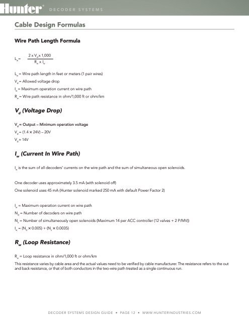
Cable <strong>Design</strong> Formulas<br />
Wire Path Length Formula<br />
L w<br />
=<br />
2 x V d<br />
x 1,000<br />
R w<br />
x I w<br />
L w<br />
= Wire path length in feet or meters (1 pair wires)<br />
V d<br />
= Allowed voltage drop<br />
I w<br />
= Maximum operation current on wire path<br />
R w<br />
= Wire path resistance in ohm/1,000 ft or ohm/km<br />
V d<br />
(Voltage Drop)<br />
V d<br />
= Output – Minimum operation voltage<br />
V d<br />
= (1.4 × 24V) – 20V<br />
V d<br />
≈ 14V<br />
I w<br />
(Current In Wire Path)<br />
I w<br />
is the sum of all decoders‘ currents on the wire path and the sum of simultaneous open solenoids.<br />
One decoder uses approximately 3.5 mA (with solenoid off)<br />
One solenoid uses 45 mA (<strong>Hunter</strong> solenoid marked 250 mA with default Power Factor 2)<br />
I w<br />
= Maximum operation current on wire path<br />
N d<br />
= Number of decoders on wire path<br />
N s<br />
= Number of simultaneously open solenoids (Maximum 14 per ACC controller (12 valves + 2 P/MV))<br />
I w<br />
= (N d<br />
× 0.005) + (N s<br />
× 0.0035)<br />
R w<br />
(Loop Resistance)<br />
R w<br />
= Loop resistance in ohm/1,000 ft or ohm/km<br />
This resistance varies by cable area and the actual values need to be verified by cable manufacturer. The resistance refers to the out<br />
and back resistance, or that of both conductors in the two-wire path treated as a single continuous run.<br />
<strong>Decoder</strong> Systems <strong>Design</strong> <strong>Guide</strong> • Page 12 • www.hunterindustries.com