Decoder Design Guide - Hunter Industries
Decoder Design Guide - Hunter Industries
Decoder Design Guide - Hunter Industries

Create successful ePaper yourself
Turn your PDF publications into a flip-book with our unique Google optimized e-Paper software.
<strong>Decoder</strong> Systems<br />
Install all grounding circuit components in straight lines. When it is necessary to make bends, do not make sharp turns. To<br />
prevent the electrode-discharged energy from re-entering the underground wires and cables, all electrodes shall be installed<br />
away from said wires and cables. The spacing between any two electrodes shall be 15 to 20 feet/4.5 to 6 m, so that they don’t<br />
compete for the same soil.<br />
The earth-to-ground resistance of this circuit is to be measured using a Megger ® , or other similar instrument, and the reading<br />
is to be no more than 10 ohms. If the resistance is more than 10 ohms, then additional ground plates and PowerSet are to be<br />
installed in the direction of an irrigated area. It is required that the soil surrounding copper electrodes be kept at a minimum<br />
moisture level of 15% at all times by dedicating an irrigation station at each controller location.<br />
<strong>Decoder</strong> Grounding<br />
At the very minimum, the grounding circuit for a decoder will include a copper ground plate and may also include 50 pounds/22<br />
kg of PowerSet ® earth contact material, as defined below and per the following detail.<br />
s section for ground Plate<br />
The copper grounding plate assemblies [Paige Electric part number 182201] must meet the minimum requirements of section<br />
250 of the NEC. They are to be made of a copper alloy intended for grounding applications and will have minimum dimensions<br />
of 4" x 36" x 0.0625" (100 mm x 1.2 m x 1.58 mm). A 10-foot/3 m continuous length (no splices allowed unless using exothermic<br />
welding process) of 10 AWG/5 mm 2 solid bare copper wire is to be attached to the plate using an approved welding process.<br />
This wire is to be connected to the decoder’s ground wire and 10 AWG/5 mm 2 bare copper "shielding wire" as shown in wiring<br />
details. A 50-pound/22 kg bag of PowerSet ® [Paige Electric part number 1820058] earth contact material must be spread so that<br />
it surrounds the copper plate evenly along its length within a 6"/15 cm wide trench per detail below. Salts, fertilizers and other<br />
chemicals are not to be used in an attempt to improve soil conductivity because these materials are corrosive and will cause the<br />
copper conductors and electrodes to erode and become less effective with time.<br />
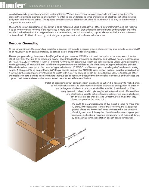
Install all grounding circuit components in straight lines. When it is necessary to make bends,<br />
do not make sharp turns. To prevent the electrode-discharged energy from re-entering<br />
the underground cables, all electrodes shall be installed 6 to 8 feet/2 to 2.5 m<br />
away from said cables, and at right angles to the two-wire path. If more than<br />
one electrode is used to achieve lower resistance, the spacing between<br />
any two electrodes shall be 15 to 20 feet/4.5 to 6 m, so that they<br />
don’t compete for the same soil.<br />
The earth-to-ground resistance of this circuit is to be no more than<br />
10 ohms. If the resistance is more than 10 ohms, then additional<br />
ground plates and PowerSet ® are to be installed in the direction<br />
of an irrigated area. It is required that the soil surrounding copper<br />
electrodes be kept at a minimum moisture level of 15% at all times<br />
by dedicating an irrigation station at each controller location.<br />
PowerSet<br />
Earth Contact Material<br />
Ground Plate (4” X 36”)<br />
<strong>Decoder</strong> Systems <strong>Design</strong> <strong>Guide</strong> • Page 16 • www.hunterindustries.com