FTC200 & FTA/FTX Quick Installation & Jumper Setting Guide Ferrotec
FTC200 & FTA/FTX Quick Installation & Jumper Setting Guide Ferrotec
FTC200 & FTA/FTX Quick Installation & Jumper Setting Guide Ferrotec

Create successful ePaper yourself
Turn your PDF publications into a flip-book with our unique Google optimized e-Paper software.
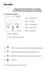
5. Board ID number Selection (SW1.3~6)<br />
The dip switch selections are for configuring multiple controllers when using the RS485<br />
communication protocol. The number sets the board ID. The default board ID number is 1.<br />
NOTE: Do not change the setting unless you are using multiple <strong>FTC200</strong> units with one master<br />
port.<br />
Serial ID<br />
SW1.3 SW1.4 SW1.5 SW1.6<br />
0 ON ON ON ON<br />
1 OFF ON ON ON<br />
Default <strong>Setting</strong><br />
2 ON OFF ON ON<br />
3 OFF OFF ON ON<br />
4 ON ON OFF ON<br />
5 OFF ON OFF ON<br />
6 ON OFF OFF ON<br />
7 OFF OFF OFF ON<br />
8 ON ON ON OFF<br />
9 OFF ON ON OFF<br />
10 ON OFF ON OFF<br />
11 OFF OFF ON OFF<br />
12 ON ON OFF OFF<br />
13 OFF ON OFF OFF<br />
14 ON OFF OFF OFF<br />
15 OFF OFF OFF OFF<br />
6. DIP SW1-7,8<br />
These switches are RESERVED and may create operational problems if not configured<br />
correctly.<br />
Please verify that both switches are set to the ON position to ensure that the <strong>FTC200</strong> will<br />
operate properly.<br />
7. Control Signal to TE amplifier<br />
There are four signal lines that are used for communications between the <strong>FTC200</strong> and <strong>FTX</strong> Hbridge<br />
Amplifier. The <strong>FTC200</strong> kit includes a 4-wire cable for you to connect these 4 signals.<br />
NOTE: When connecting the system, please make sure the connection names are matched.<br />
PWM pulse width modulation,<br />
DIR hot/cold direction,<br />
ENB enable,<br />
GND ground)<br />
<strong>FTC200</strong> <strong>Jumper</strong> and Connector Configuration - 0907 Page 7 of 8