

Stratomaster Smart Single - STRATOMASTER Instrumentation MGL ...
Stratomaster Smart Single - STRATOMASTER Instrumentation MGL ...
Stratomaster Smart Single - STRATOMASTER Instrumentation MGL ...

Create successful ePaper yourself
Turn your PDF publications into a flip-book with our unique Google optimized e-Paper software.
<strong>Stratomaster</strong> <strong>Smart</strong> <strong>Single</strong><br />
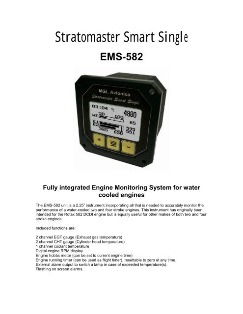
EMS-582<br />
Fully integrated Engine Monitoring System for water<br />
cooled engines<br />
The EMS-582 unit is a 2.25” instrument incorporating all that is needed to accurately monitor the<br />
performance of a water-cooled two and four stroke engines. This instrument has originally been<br />
intended for the Rotax 582 DCDI engine but is equally useful for other makes of both two and four<br />
stroke engines.<br />
Included functions are:<br />
2 channel EGT gauge (Exhaust gas temperature)<br />
2 channel CHT gauge (Cylinder head temperature)<br />
1 channel coolant temperature<br />
Digital engine RPM display<br />
Engine hobbs meter (can be set to current engine time)<br />
Engine running timer (can be used as flight timer), resettable to zero at any time.<br />
External alarm output to switch a lamp in case of exceeded temperature(s).<br />
Flashing on screen alarms.
Setting up the EMS-582<br />
Press the Menu key to enter the menu. You can move forward and backwards in the menu by<br />
using the + and – keys. To change or select a menu item, move the highlight to the desired item<br />
and then press the Menu key. To end an edit or function, press the Menu key again.<br />
To exit the menu and continue normal operation, select the ***Done*** function and press the<br />
Menu key. Note, all changes you have initiated during your session will only be remembered by<br />
the instrument if you exit the menu using the ***Done*** function.<br />
Zero FT<br />
This function allows you to set the flight timer to zero. The flight timer counts hours and minutes<br />
while the engine is running.<br />
Set Hobbs<br />
This function allows you to set the hobbs meter to<br />
your current engine running time.<br />
Use the plus and minus buttons to change the<br />
indicated part of the hobbs reading. Use the Menu<br />
button to change from hour hundreds to hours to<br />
minutes.<br />
Moving the update cursor below the numbers past<br />
the minutes field on the right ends the edit of the hobbs meter reading and stores any changes.
Temp in …<br />
Choose your temperature units. You can select Degrees Celsius or Degrees Fahrenheit.<br />
Contrast …<br />
This function allows you to change the display contrast to your liking. You can select values from<br />
about 20 to 45. (May vary with different displays)<br />
Calib ...<br />
Enter the number of pulses per revolution.<br />
You can enter fractions of a pulse in case of engines that generate a non-integer number of<br />
pulses per revolution.<br />
Typical settings:<br />
Rotax 582 DCDI – 6.0<br />
Rotax 532 <strong>Single</strong> ignition 1.0 or 2.0 depending on wiring.<br />
Most four stroke engines four cylinder: 2.0<br />
Most four stroke engines three cylinder: 1.5<br />
Most four stroke engines two cylinder: 1.0<br />
5 cylinder radial: 2.5<br />
Using this function you can adapt the EMS-582 to most other makes of two-stroke and four stroke<br />
engines.<br />
BL …<br />
This function allows you to switch the display backlight on or off.<br />
CHT<br />
Select if you would like to activate the 2 channel CHT display. This requires that you connect two<br />
CHT probes. These probes are optional as monitoring CHT on this engine is considered of lessor<br />
importance due to the monitoring of coolant temperature.<br />
Please note that should you obtain CHT probes that you must fit K-Type thermocouple based<br />
senders.<br />
Should you enable the CHT display, the CHT readings will alternate with the standard EGT<br />
readings every few seconds.<br />
WTP<br />
Select if you are going to use the standard coolant temperature sender or the optional precision<br />
sender available from <strong>MGL</strong> Avionics. The standard sender has one wire, using the engine block<br />
as electrical connection while the precision sender has two wires. It is electrically isolated from<br />
the engine block and is based on a small temperature measurement chip.<br />
Selecting the incorrect sender type will result in incorrect temperature readout.<br />
CHTx …<br />
This function allows you to select the CHT temperature alarm limit most suitable for your<br />
application. You select the limit applicable for the two cylinder head temperature channels (note<br />
that you need to enable them should you want to use them).
Typical CHT limits range from 150 degrees C for water cooled engines to about 250 degrees C<br />
for air cooled engines. The Rotax 582 engine should not exceed 150 degrees C cylinder<br />
temperature. Consult your engines handbook for the most suitable limit for your engine.<br />
Note that it is possible to use the two CHT channels for much higher temperatures as well, such<br />
as found with exhaust gas temperature probes. This way it is possible to use the instrument to<br />
measure four channels of EGT for example.<br />
For a table of temperature limits and ranges, please view the description under the following<br />
heading “EGTx”.<br />
EGTx …<br />
This function allows you to select the EGT temperature alarm limit most suitable for your<br />
application. You select the limit applicable for the two exhaust gas temperature channels. Typical<br />
EGT limits range from 650 degrees C for two stroke engines to about 900 degrees C for turbo<br />
charged four stroke engines. Consult your engines handbook for the most suitable limit for your<br />
engine. The Rotax 582 engine has a 650 degree C limit.<br />
Note that it is possible to use the two EGT channels for much lower temperatures as well, such<br />
as found with cylinder head temperature probes. This way it is possible to use the instrument to<br />
measure four channels of CHT for example.<br />
You can select from the following temperature limit and display range table:<br />
Limit (Alarm)<br />
Range of display (bargraph only)<br />
150°C / 300°F 200°C / 400°F<br />
180°C / 350°F 250°C / 500°F<br />
200°C / 400°F 250°C / 500°F<br />
250°C / 480°F 300°C / 580°F<br />
300°C / 570°F 350°C / 660°F<br />
400°C / 750°F 500°C / 930°F<br />
650°C / 1200°F 700°C / 1300°F<br />
720°C / 1320°F 800°C / 1500°F<br />
760°C / 1400°F 820°C / 1520°F<br />
815°C / 1500°F 850°C / 1560°F<br />
850°C / 1560°F 900°C / 1650°F<br />
900°C / 1650°F 1000°C / 1830°F<br />
WTx …<br />
This function allows you to select the temperature limit (alarm level) for your coolant temperature<br />
monitor. You can select from the following limits:<br />
Limit (Alarm)<br />
Range of display (bargraph only)<br />
80°C / 176°F 90°C / 190°F<br />
85°C / 185°F 100°C / 210°F<br />
90°C / 194°F 110°C / 230°F<br />
95°C / 203°F 120°C / 250°F<br />
100°C / 212°F 120°C / 250°F<br />
110°C / 230°F 130°C / 260°F<br />
ADC<br />
This function is for technical personal. It is not used for ordinary operation of the unit.
Technical specifications:<br />
Display temperature range (operational): -20 to +80 degrees C<br />
Supply voltage: +8 to +18V. +24/28V with optional pre regulator.<br />
Supply current: 25mA/45mA (backlight off/on)<br />
Thermocouples: K-type<br />
Measurement range EGT: User programmable (digital to 1200 degrees C)<br />
Measurement range CHT: User programmable (digital to 1200 degrees C)<br />
Alarm level EGT: User programmable<br />
Alarm level CHT: User programmable<br />
Technology: Fully cold junction compensated using precision internal temperature reference.<br />
Measurement accuracy: +/- 5 degrees typical over full temperature range if used with<br />
<strong>Stratomaster</strong> EGT and CHT probes.<br />
Measurement interval: 2 seconds per channel.<br />
Inputs: Differential, can use grounded and isolated probes.<br />
Common mode voltage range: -2V to +3V<br />
Measurement range Coolant standard sender: 20 to 110 degrees C<br />
Measurement range Coolant precision sender: 20 to 180 degrees C<br />
Accuracy standard sender: +/- 5% at 80 degrees C.<br />
Accuracy precision sender: +/- 2% over full temperature range.<br />
Alarm contact:<br />
Maximum permissible current through alarm contacts: 500mA.<br />
Maximum permissible voltage over alarm contacts: 50V.<br />
Typical load for alarm contacts: 12V/1W lamp. Be aware of low resistance of higher wattage<br />
lamps. A cold filament resistance of 20 ohms or less will damage the internal alarm relay contact.<br />
Rev counter:<br />
Crystal based accuracy, resolution 20 RPM typical, dependent on number of pulses per<br />
revolution<br />
from engine and "Calib" setup. Range 0-9999 revs.<br />
Minimum signal for stable display: 2Vpp.<br />
Fully A/C coupled, maximum voltage +/- 40V.<br />
RF noise filter plus Schmidt trigger based input.<br />
Note: It is essential that a single wire be connected from the minus terminal of the<br />
instrument to the engine block (Brown wire on Rotax 582 engines). This wire must not be<br />
used to share currents with other electrical users as this will affect accuracy of indicated<br />
temperatures and can affect the REV counter reading adversely.<br />
Warranty:<br />
<strong>MGL</strong> avionics warrants their products for a period of one year from date of purchase against<br />
faulty workmanship. Warranty is limited to the replacement of faulty components and includes the<br />
cost of labor. Shipping costs are for the account of the purchaser.<br />
Note for operation on supplies with inductive loads:<br />
Any operation of electronic instrumentation on power supplies that are subject to high voltages<br />
caused by operation of inductive loads (starter motors, solenoids, relays) are required to be fitted<br />
with suitable protection.
All <strong>Smart</strong> <strong>Single</strong>s are guaranteed to withstand temporary over voltage up to 40V without<br />
additional protection. We recommend that measures are taken to prevent voltage transients in<br />
excess of this limit.<br />
<strong>MGL</strong> Avionics recommends the fitment of a fuse in line with a 33V transorb (available from <strong>MGL</strong><br />
Avionics at low cost) to protect electronic instruments, radios and intercom systems. Only one<br />
such arrangement is required for a cluster of instruments.<br />
Please note that product warranty excludes damages caused by unprotected, unsuitable or<br />
incorrectly wired electrical supplies.<br />
Installing the EMS-582<br />
Connect sender body to<br />
ground via engine block<br />
The two CHT probes and two EGT probes are wired as shown above. Note that the CHT probes<br />
are optional. Most installations do not monitor CHT temperatures as coolant temperature is<br />
monitored.<br />
Connect probes according to the colors of the wires. These are red and yellow for <strong>MGL</strong> probes.<br />
The coolant temperature sender is available in two types. The standard sender included with the<br />
instrument package has a single terminal. Connect this terminal to the H2O input as shown<br />
above. The sender requires one further connection which is via the sender body, engine block<br />
and the reference wire. Please ensure that you have a good electrical connection on this<br />
reference ground as outlined further below. Any currents flowing through this connection caused<br />
by OTHER electrical users in your system WILL cause incorrect temperature readings.<br />
Note that no sealant is required to fit the sender. The sender has a tapered thread that is self<br />
sealing. Good electrical connection between the sender body and the engine block is a<br />
requirement.<br />
Shown is typical wiring used to connect a 12V lamp as external alarm indicator. Note that the two<br />
terminals used for the alarm are the contacts of a switch. The switch is closed when the alarm is
active. If you have more than one instrument with alarm contacts, you can wire all contacts in<br />
parallel so you can use a single lamp if so desired. A 12V/0.5W or 1W lamp is the usual choice.<br />
Power supply here assumes a 12V DC source. It is recommended to install suitable protection<br />
against over voltage such as can be generated by solenoids and starter motors. The above<br />
suggestion uses a fuse and a transorb. The transorb is available from <strong>MGL</strong> Avionics at very low<br />
cost. This device ensures that the voltage across it cannot rise above 33V, the transorb will cause<br />
the fuse to blow if prolonged over voltage is present.<br />
Note that you only need a single fuse and transorb to protect a cluster of several instruments.<br />
Please install the transorb as close as possible from a wiring point of view to the instruments.<br />
You can use the protected power for your radio, intercom or other low current users.<br />
Keep this power rail separated from high current rails for lamps etc.<br />
Be sure to install a reference connection between the minus terminal of the instrument and the<br />
engine block. On the Rotax 582, this is available on the connector block as the Brown wire.<br />
Finally, connect the Grey REV counter wire as shown above.<br />
Should you find unstable RPM readings, you may have a burned magneto coil. This can happen<br />
if you have used low impedance rev counters before. In this case you can try fitting a 220 ohm<br />
resistor from the grey wire to the brown wire. Alternatively, you can connect the REV counter<br />
terminal to one of the yellow lighting coil wires if you have a rectifier/regulator fitted.<br />
Installing the precision coolant temperature probe<br />
The precision temperature probe is available as an option. This probe is fully insulated from the<br />
engine block and it is recommended for difficult installations in the electrical sense.<br />
The probe has two wires. Connect the red wire to the H2O probe and the remaining wire to the<br />
instruments ground terminal. The sender body does not have to have an electrical connection to<br />
the engine block and you can use sealant if you have to for some reason. The sender body does<br />
have a tapered thread that does not require sealant.<br />
After you have installed the sender, please select the correct sender type in the menu (Item<br />
WTP). If you do not select the correct sender type, the temperature shown will be incorrect.<br />
Extending leads of probes and senders<br />
Thermocouple leads as used with the EGT and CHT probes can be extended either with ordinary<br />
copper cable or with special K-Type extension cable. The choice of either depends on your<br />
desired accuracy.
If it is possible in your installation to ensure that both ends of a copper extension cable will be at<br />
the same temperature (or very close), then it is quite possible to use the copper cable. In most<br />
open-air installations this will be the case.<br />
Should this not be possible or you require best possible accuracy at all times, you can obtain a<br />
special K-type extension cable. This cable is made from the same metals as your probes cable<br />
but uses ordinary plastic sleeving to save costs.<br />
In either case, ensure that the cable is not routed close to sources of electromagnetic interference<br />
of any kind. The voltages present in this cable are very small and are subject to changes applied<br />
by external fields. This can lead to false temperature indications.<br />
You can check your installation by using a hand-held transmitter, such as an airband radio. If you<br />
transmit a signal, no change in temperature reading should occur.<br />
Should you need to extend the precision water temperature sender, you can do so with ordinary<br />
copper cable. It is recommended that you choose a cable similar to the type used and continue<br />
the twist of the cable for its entire length.<br />
The standard temperature sender does not have a lead fitted. Use a standard copper cable to<br />
make the connection. The length is not critical. Ensure that you have a lead from the engine block<br />
back to the ground terminal of the instrument. Do not route this return lead via the battery minus<br />
or other high current users as this may lead to false temperature readings due to voltage drops<br />
caused in the cable by these users.<br />
If you have difficulty obtaining a stable rev counter reading:<br />
The instrument relies on a reasonably clean and unambiguous signal being present. Signals<br />
containing noise and/or secondary signals may result in a “jumpy” or unstable RPM reading. For<br />
Rotax 582 DCDI engine it is often (but not always) beneficial to install a ballast resistor of 220<br />
ohm or less value between the grey rev counter wire and ground. This can be done at the<br />
instrument REV counter terminals. It is further important that a direct connection between the<br />
instrument ground and the engine block exists. Install a wire separate from your supply minus if<br />
required.<br />
In case of it not being possible to use the grey REV counter wire, consider using any of the two<br />
yellow lighting coil wires. You need to connect these to a regulator/rectifier or at least some form<br />
of ballast. Do not use these wires if no ballast of any kind is available as in this case the voltage<br />
on these wires may reach several thousand volts.<br />
Ensure that your rev counter wire does not travel next to any wires containing pulsed signals such<br />
as ignition wires (spark plug wires). The very high voltage signals may couple onto your rev<br />
counter wire and these will be sensed by the EMS-582 as additional pulses.<br />
On some engines rev counter signals may be too high in voltage. The EMS-582 does accept<br />
these voltages typically without damage but the relatively sensitive input may also “see” smaller<br />
artifacts of such a signal and count them as pulses, thus giving a wrong reading. In cases like this<br />
it is helpful to wire a resistor in series to the rev counter input of the instrument. Values like 10K,<br />
22K or 33K may be helpful.<br />
The input may also be used with a variety of sensors like gear tooth sensors, optical pickups or<br />
hall effect devices. Please see the owners manual of our RV-1 rev counter for more info.


