Ada User Guide for LEGO MINDSTORMS NXT - DIT - Universidad ...
Ada User Guide for LEGO MINDSTORMS NXT - DIT - Universidad ...
Ada User Guide for LEGO MINDSTORMS NXT - DIT - Universidad ...

You also want an ePaper? Increase the reach of your titles
YUMPU automatically turns print PDFs into web optimized ePapers that Google loves.
<strong>Ada</strong> <strong>User</strong> <strong>Guide</strong> <strong>for</strong> <strong>LEGO</strong> <strong>MINDSTORMS</strong> <strong>NXT</strong><br />
Peter J. Bradley, Juan A. de la Puente, Juan Zamorano.<br />
<strong>Universidad</strong> Politécnica de Madrid, Madrid, Spain.<br />
http://polaris.dit.upm.es/str<br />
Abstract<br />
The purpose of this guide is to introduce the robotics kit<br />
<strong>LEGO</strong> <strong>MINDSTORMS</strong> <strong>NXT</strong> to the <strong>Ada</strong> community. All<br />
the steps required to complete a working <strong>Ada</strong> application<br />
running under the <strong>LEGO</strong> <strong>MINDSTORMS</strong> <strong>NXT</strong> are<br />
covered.<br />
Keywords:<br />
<strong>LEGO</strong>, <strong>MINDSTORMS</strong>, <strong>Ada</strong>, Ravenscar, Real-Time,<br />
Embedded, Robotics.<br />
2 <strong>MINDSTORMS</strong> <strong>NXT</strong><br />
2.1 Architecture overview<br />
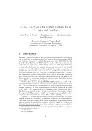
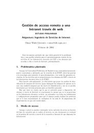
The <strong>NXT</strong> kit comes with a programmable controller, also<br />
called Intelligent Brick. This Brick (see figure 1 <strong>for</strong> its<br />
block diagram) features a 32-bit ARM main processor<br />
(AT91SAM7S256) with 64 KB of RAM and 256 KB of<br />
Flash memory that runs at 48 MHz. To assist the main<br />
processor an 8-bit AVR co-processor (ATmega48) is also<br />
included. Main processor and co-processor periodically<br />
communicate through an I 2 C bus.<br />
1 Introduction<br />
The <strong>LEGO</strong> <strong>MINDSTORMS</strong> <strong>NXT</strong> (from now on <strong>NXT</strong>)<br />
is a simple and flexible robotics kit that allows <strong>Ada</strong> programmers<br />
to develop applications that interact with the<br />
“outside world” by means of sensors, actuators, etc. The<br />
dynamic features associated to this interaction with the<br />
physical environment require that the actions of the control<br />
software are executed at a specified time rate. There<strong>for</strong>e,<br />
real-time constraints must be generally met. <strong>Ada</strong>’s<br />
concurrency and real-time integrated features together<br />
with the use of the Ravenscar profile [1] makes it the<br />
ideal language <strong>for</strong> the <strong>NXT</strong>.<br />
This guide is organised as follows. The first section is<br />
this introduction. Then, the second section shows some<br />
fundamental aspects of the <strong>NXT</strong> hardware that should be<br />
kept in mind <strong>for</strong> <strong>NXT</strong> <strong>Ada</strong> development. Section three<br />
briefly introduces <strong>Ada</strong> programming <strong>for</strong> the <strong>NXT</strong> taking<br />
into consideration the Ravenscar compliant <strong>NXT</strong> runtime<br />
system and the <strong>NXT</strong> <strong>Ada</strong> drivers library. The fourth<br />
section gives an overview of the development environment<br />
with a description of the tools required to work with the<br />
<strong>NXT</strong>. As an example, the development of a prototype<br />
vehicle, is presented in section five. Finally, section six<br />
describes how the internal JTAG interface of the <strong>NXT</strong> is<br />
accessed and used to debug <strong>Ada</strong> programs.<br />
Throughout this guide the <strong>Ada</strong>Core GNAT GPL <strong>for</strong><br />
<strong>LEGO</strong> <strong>MINDSTORMS</strong> <strong>NXT</strong> 2011 hosted in GNU/Linux<br />
<strong>for</strong> x86 (available from http://polaris.dit.upm.es/<br />
str/projects/mindstorms) will be used but note that<br />
the Windows version is also available (http://libre.<br />
adacore.com/libre/tools/mindstorms).<br />
<br />
<br />
<br />
<br />
<br />
<br />
<br />
<br />
<br />
<br />
<br />
<br />
<br />
<br />
Figure 1: <strong>NXT</strong> block diagram.<br />
<br />
<br />
<br />
<strong>LEGO</strong> Group ©<br />
It also has three output ports, which are bidirectional,<br />
to connect and control actuators such as electrical motors<br />
or linear actuators and four input ports that support both<br />
digital and analog sensors.<br />
Communications with the Brick are possible using either<br />
USB, via a full-speed USB 2.0 port, or Bluetooth,<br />
available through a CSR BlueCore 4 chip that is connected<br />
to the ARM’s USART. The USB 2.0 port is usually<br />
used to connect to a PC and Bluetooth to communicate<br />
with other <strong>NXT</strong> Bricks or any other Bluetoothenabled<br />
devices such as smartphones, tablets, etc.<br />
On the top of the Brick there is a 100 x 64 pixel LCD<br />
display connected to the main processor via a SPI bus<br />
(serial peripheral interface bus), and four rubber buttons,<br />
controlled by the co-processor, <strong>for</strong> interacting with the<br />
Brick.<br />
The <strong>NXT</strong> Brick also comes with an audio amplifier,
connected to the ARM PWM (pulse-width modulation)<br />
controller, and a 16 Ω speaker with a bandwidth of 2 - 16<br />
KHz.<br />
For schematics and further in<strong>for</strong>mation refer to <strong>LEGO</strong><br />
<strong>MINDSTORMS</strong> <strong>NXT</strong> Hardware Developer Kit [2].<br />
2.2 Processor and co-processor<br />
The AVR co-processor handles the following low-level<br />
tasks <strong>for</strong> the main processor:<br />
• Power management. Turns the <strong>NXT</strong> Brick off<br />
and wakes it up when the center orange button is<br />
pressed. It also monitors the battery status sending<br />
in<strong>for</strong>mation to the ARM processor.<br />
• PWM generation. Generates pulses <strong>for</strong> the three<br />
output ports at a frequency of 8 KHz with the duty<br />
cycle specified by the ARM processor.<br />
• A/D conversion. Per<strong>for</strong>ms a 10 bit digital conversion<br />
of the analog signals at the input ports every 3<br />
ms.<br />
• Button decoding. Decodes the buttons so that<br />
the main processor is able to tell which buttons<br />
are pressed and which are not. Note that the coprocessor<br />
does not carry out any button debouncing.<br />
If it is not handled at driver level the programmer<br />
should take care of it.<br />
To handle all of the above it is necessary <strong>for</strong> main processor<br />
and co-processor to periodically exchange in<strong>for</strong>mation.<br />
The communication between the two microcontrollers<br />
is set up as two memory allocations that, on the<br />
original <strong>LEGO</strong> firmware, are updated on both microcontrollers<br />
every 2 ms. The communication interface operates<br />
at 380 Kbit/s using the I 2 C hardware interface<br />
in both microcontrollers with the ARM main processor<br />
functioning as master.<br />
2.3 Output ports<br />
1<br />
2<br />
3<br />
4<br />
5<br />
6<br />
M0<br />
M1<br />
GND<br />
POWER<br />
TACHO0<br />
TACHO1<br />
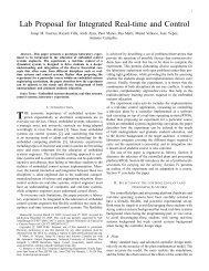
Figure 2: Output port generic schematic.<br />
All of the three output ports work in the same manner,<br />
see figure 2. They have a ground (GND) and a 4.3<br />
V supply output (POWER). Two output signals (M0 &<br />
M1)that come from an internal H-bridge motor driver<br />
that controls the motor standby, <strong>for</strong>ward, reverse or brake<br />
modes. This motor driver is governed by the PWM pulses<br />
generated by the co-processor. It also has two input signals<br />
(TACHO0 & TACHO1) that are connected to the<br />
main processor’s parallel input/output controller (PIO)<br />
using a Schmitt trigger <strong>for</strong> noise suppression. Within the<br />
<strong>Ada</strong> drivers these two last signals are used <strong>for</strong> the motor<br />
encoder. The encoder has a resolution of 360 counts per<br />
revolution. When the motor rotates the ARM processor<br />
receives an interrupt in order to update the encoder<br />
counter through the parallel I/O controller. Notice that<br />
clockwise and counterclockwise operation is detected by<br />
the counter’s increments or decrements.<br />
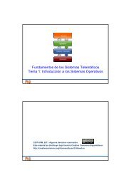
2.4 Input ports<br />
Depending on the type of sensor connected to the <strong>NXT</strong><br />
Brick the input ports behave differently. The input ports<br />
allow both digital and analog interfaces, see figure 3.<br />
1<br />
2<br />
3<br />
4<br />
5<br />
6<br />
ANA<br />
GND<br />
GND<br />
POWER<br />
DIG0<br />
DIG1<br />
Vcc 5 V<br />
10 K<br />
Figure 3: Input <strong>NXT</strong> generic schematic.<br />
<strong>LEGO</strong> considers three types of sensors:<br />
• Active sensors. These kind of sensors belong to<br />
the previous version of <strong>LEGO</strong> <strong>MINDSTORMS</strong>, the<br />
RCX. They require an <strong>NXT</strong> adapter cable. <strong>NXT</strong><br />
firmware provides the same functionality available<br />
in the RCX Bricks by using an extra current source.<br />
This current source delivers power (approximately<br />
18 mA) to the active sensors. It supplies power to<br />
the sensor through the analog pin (ANA) during 3<br />
ms and then measures the analog value during the<br />
following 0.1 ms. The AVR sends the 10 bit digital<br />
conversion of the analog value to the main processor<br />
using the scheme presented in section 2.2.<br />
When using these kind of sensors (e.g. RCX<br />
light sensor, RCX rotation sensor) be sure to set<br />
the appropriate input power settings by calling<br />
Set Input Power( sensor id ,RCX 9V) from <strong>NXT</strong>.AVR<br />
driver package where sensor id is the input port<br />
used <strong>for</strong> the active sensor.<br />
• Passive sensors. These kind are analog sensors<br />
that do not need the special power/measurement<br />
timing of the active sensors. The power needs of<br />
these sensors are not covered via the analog pin<br />
(ANA) but via a specific pin (POWER). Note that<br />
the sampling of all the AVR A/D converters occurs<br />
simultaneously so active and passive sensors must be<br />
sampled at the same rate, 333 Hz.
All of the sensors packed with the <strong>LEGO</strong> MIND-<br />
STORMS <strong>NXT</strong> are passive with the exception of the<br />
ultrasonic sensor.<br />
• Digital sensors. These sensors contain all the necessary<br />
logic and processing resources to work independently.<br />
Thus, they per<strong>for</strong>m their function autonomously<br />
and send or receive in<strong>for</strong>mation to/from<br />
the ARM via an I 2 C channel (DIGI0 & DIGI1) running<br />
at 9600 bit/s where the ARM functions as master.<br />
These sensors are mapped as external memory<br />
areas from/to which the programmer can read<br />
or write to control the behaviour of the sensor and<br />
harvest data. For a memory arrangement that optimizes<br />
read and write access refer to <strong>LEGO</strong> MIND-<br />
STORMS <strong>NXT</strong> Hardware Developer Kit [2].<br />
The ultrasonic sensor is the only digital sensor<br />
packed in the <strong>NXT</strong> kit.<br />
If a higher sampling rate is required by an analog input<br />
the hardware allows configuring DIGI1 as an analog<br />
input.<br />
Port 4 can also function as a high-speed communication<br />
port. It has a RS485 IC that allows <strong>for</strong> high-speed-bidirectional<br />
multipoint communications.<br />
2.5 Bluetooth features<br />
The <strong>NXT</strong> Brick can be connected using Bluetooth to any<br />
other Bluetooth device that implements the Serial Port<br />
Profile (SPP), a serial cable emulation profile. The effective<br />
working Bluetooth range <strong>for</strong> the <strong>NXT</strong> Brick is<br />
approximately 10 m (Bluetooth Class II device).<br />
The <strong>NXT</strong> Brick provides a master/slave communication<br />
scheme with four channels. Channel 0 is used when<br />
working as slave and the other three when working as<br />
master. The <strong>NXT</strong> Brick can either work as master or<br />
slave. This means that when the <strong>NXT</strong> Brick works as<br />
master it can communicate with three more devices.<br />
The CSR BlueCore 4 firmware is implemented as a virtual<br />
machine with an integrated command interpreter.<br />
Thus, communication between the main ARM processor<br />
and the Bluetooth chip is handled by a set of defined<br />
commands and data streams that are exchanged through<br />
the USART channel. Refer to <strong>LEGO</strong> <strong>MINDSTORMS</strong><br />
<strong>NXT</strong> ARM7 Bluetooth Developer Kit [3] <strong>for</strong> a full specification.<br />
3 <strong>Ada</strong> programming <strong>for</strong> <strong>NXT</strong><br />
3.1 <strong>NXT</strong> run-time system<br />
The <strong>Ada</strong>Core GNAT GPL <strong>for</strong> <strong>LEGO</strong> <strong>MINDSTORMS</strong><br />
<strong>NXT</strong> 2011 cross-compiler toolchain relies on a Ravenscar<br />
small footprint run-time system (Ravenscar SFP).<br />
It is really a superset of the zero footprint profile. It<br />
adds the specification of a secondary stack mechanism<br />
<strong>for</strong> unconstrained objects and the Ravenscar tasking features<br />
to the zero footprint profile. This means that <strong>Ada</strong><br />
applications <strong>for</strong> the <strong>NXT</strong> should comply with the Ravenscar<br />
profile <strong>for</strong> tasking purposes. Also, as it is targeted<br />
<strong>for</strong> use with embedded systems, it uses a sequential <strong>Ada</strong><br />
subset where not all language features are available. For<br />
example, attributes ’Image and ’Value are not included.<br />
Moreover, there is no exception propagation. Unhandled<br />
exceptions jump to a “last chance handler” that can be<br />
reprogrammed as desired as long as the application then<br />
terminates (it must not return to the caller). Note that<br />
you must explicitly include the package <strong>NXT</strong>.Last Chance,<br />
using a with-clause, <strong>for</strong> it to be part of your application.<br />
If you do not, a default handler is included that only<br />
displays an address <strong>for</strong> the exception on the <strong>NXT</strong> LCD<br />
screen. For a full description of the Ravenscar SFP profile<br />
refer to GNAT <strong>User</strong>’s <strong>Guide</strong> “Supplement <strong>for</strong> High-<br />
Integrity Edition Plat<strong>for</strong>ms” [4].<br />
The purpose of the Ravenscar profile is to restrict the<br />
use of many tasking facilities so that the outcome of the<br />
program is predictable. For this purpose, the profile is<br />
restricted to a fixed priority and pre-emptive scheduling.<br />
With fixed priority pre-emptive scheduling, the scheduler<br />
ensures that at any given time, the processor executes the<br />
highest priority task of all those tasks that are currently<br />
ready to be executed. Also, the Immediate Ceiling Priority<br />
Protocol (ICPP) is en<strong>for</strong>ced by the Ravenscar profile.<br />
This means that when a task locks the resource, its priority<br />
is temporarily raised to the priority ceiling of the<br />
resource, thus no task that may lock the resource is able<br />
to get scheduled. This allows execution of a low priority<br />
task deferring execution of higher-priority tasks, thus<br />
minimizing priority inversion. More in<strong>for</strong>mation can be<br />
found in Annex D: Real-Time Systems of the <strong>Ada</strong> 2005<br />
Reference Manual [5].<br />
When writing an <strong>Ada</strong> application <strong>for</strong> <strong>NXT</strong> you should<br />
bear in mind that only the <strong>Ada</strong> subset defined by the<br />
Ravenscar profile can be used <strong>for</strong> tasking. These are some<br />
of the restrictions:<br />
• requeue statement.<br />
• abort statements.<br />
• Task entries.<br />
• Dynamic priorities.<br />
• Relative delays.<br />
• Protected types with more than one entry.<br />
• Protected entries with barriers other than a single<br />
boolean variable declared within the same protected<br />
type.<br />
• Entry calls to a protected entry with a call already<br />
queued.<br />
• select statements.<br />
• Task termination.<br />
For a full and detailed list refer to <strong>Guide</strong> <strong>for</strong> the use of<br />
the <strong>Ada</strong> Ravenscar Profile in high integrity systems [1].
3.2 <strong>NXT</strong> <strong>Ada</strong> drivers<br />
The <strong>NXT</strong> drivers developed by <strong>Ada</strong>Core are completely<br />
coded in <strong>Ada</strong>. These drivers are based on those of the<br />
LeJOS Project. The LeJOS Project is a tiny Java virtual<br />
machine ported to the <strong>NXT</strong> Brick in 2006 (http:<br />
//lejos.source<strong>for</strong>ge.net).<br />
These drivers have undergone major updates in the last<br />
two versions of GNAT GPL <strong>for</strong> <strong>MINDSTORMS</strong> (2010 &<br />
2011) so 2010 programs might not compile with the 2011<br />
compiler. Un<strong>for</strong>tunately, <strong>Ada</strong>Core does not supply API<br />
documentation with the drivers. It is convenient to revise<br />
the drivers’ code to understand how they work. A full<br />
description of the drivers is out of the scope of this guide.<br />
For every <strong>Ada</strong> <strong>NXT</strong> program the <strong>NXT</strong>.AVR package<br />
must always be imported even if its functions are not<br />
required. The body of this package contains a periodic<br />
task called Pump, with the highest priority, executed every<br />
20 ms, that handles the co-processor communications<br />
(explained in subsection 2.2) using a circular buffer. By<br />
adding a with-clause to the main program and importing<br />
<strong>NXT</strong>.AVR the execution of this task within the program<br />
is guaranteed. It is also advisable to import <strong>NXT</strong>.Display<br />
and <strong>NXT</strong>.Last Chance <strong>for</strong> exception handling.<br />
High-level access to motors and sensors is available<br />
through a series of object oriented interfaces that provide<br />
a tagged type, a constructor function and some operations.<br />
<strong>NXT</strong>.Motors and <strong>NXT</strong>.I2C Sensors packages provide<br />
abstract types and primitive operations. This object<br />
oriented structure eases extending the code with new<br />
drivers <strong>for</strong> third-party sensors. For AVR connected peripherals<br />
(analog sensors, motors, buttons, etc.) the lowlevel<br />
package <strong>NXT</strong>.AVR can also be used.<br />
Note that these drivers provide user-transparent button<br />
debouncing through the <strong>NXT</strong>.Filtering package.<br />
Both AVR and Bluetooth interfaces per<strong>for</strong>m checksum<br />
analysis <strong>for</strong> all data exchanged with the main processor<br />
to discard inconsistent data.<br />
When using the concurrency features available with the<br />
Ravenscar profile it must be considered that the display<br />
and AVR drivers do not implement a thread-safe environment.<br />
LCD data and the circular buffer with the outgoing<br />
messages to the AVR are defined as global variables<br />
with no access control. For concurrent access to the display<br />
the <strong>NXT</strong>.Display.Concurrent package provided can be<br />
used. For AVR concurrent access a thread-safe solution<br />
must be provided by the user to avoid race conditions<br />
when calling Power Down, Set Power and Set Input Power<br />
procedures. Notice, that because of the periodic task that<br />
handles ARM - AVR communications, every time a motor<br />
is used or a power down to the <strong>NXT</strong> is set, race condition<br />
issues are present. The 2010 GNU/Linux GNAT version<br />
provided modified drivers that addressed this issue but<br />
since the 2011 GNU/Linux version changed its interface<br />
the solution has not yet been adapted.<br />
4 Development Environment<br />
4.1 Tools overview<br />
A cross-compiler toolchain is a set of tools (essentially<br />
a compiler, an assembler and a linker) that create executable<br />
code <strong>for</strong> a plat<strong>for</strong>m, in this case the <strong>NXT</strong> main<br />
processor (ARMv3 architecture), other than the one on<br />
which the tools run, that is, GNU/Linux x86. Crosscompiler<br />
toolchains are used to compile code <strong>for</strong> a plat<strong>for</strong>m<br />
upon which it is not feasible to do the compiling.<br />
<strong>Ada</strong>Core has ported the GNAT compiler toolchain to the<br />
ARM architecture by porting part of the LEON-based<br />
Open Ravenscar Real-Time Kernel (ORK+) 1 developed<br />
by a team of the Department of Telematics Engineering<br />
from the Technical University of Madrid (<strong>DIT</strong>/UPM) [6].<br />
4.2 Compiling a program<br />
The <strong>NXT</strong>’s original firmware <strong>for</strong> the main processor is<br />
completely removed (this invalidates the warranty) and<br />
replaced by a binary image of the user’s <strong>Ada</strong> application<br />
that is executed from RAM. Flash memory is not used.<br />
This means that every time a program is executed it must<br />
first by uploaded to RAM.<br />
Instead of using the widespread ELF as executable file<br />
<strong>for</strong>mat the EABI <strong>for</strong>mat is used by the GNAT crosstoolchain.<br />
EABI has been created as a common binary<br />
interface so that object code and libraries created with<br />
one toolchain can be linked to a project created with a<br />
different one.<br />
To generate an executable <strong>NXT</strong> file from the user’s<br />
<strong>Ada</strong> application the GNAT cross-toolchain needs first to<br />
compile and then link to RAM all compiled code using<br />
kernel_samba.ld linker script. The code that needs to<br />
be compiled is the user’s <strong>Ada</strong> code, the run-time system,<br />
the <strong>Ada</strong> <strong>NXT</strong> required drivers, nxt main() C function<br />
(main.c), a low-level routine to initialise the system<br />
(init.s), a low-level interrupt handler routine (irq.s),<br />
a vector table that is remapped to RAM (vectors.s) by<br />
init.s and the elaboration code generated by the GNAT<br />
binder.<br />
A GNU make script (Makefile.inc) is in charge of<br />
building the binary image that is uploaded. This script<br />
compiles the run-time libraries every time since precompiled<br />
library units are not used.<br />
4.3 Uploading a program<br />
With no firmware, when the orange button of the <strong>NXT</strong><br />
Brick is pressed the ARM main processor executes the default<br />
Boot Program (SAM-BA Boot Assistant) located in<br />
the first two sectors of the Flash memory. The SAM-BA<br />
Boot Assistant supports serial communications through<br />
the USB Device Port.<br />
Lib<strong>NXT</strong> is a utility library <strong>for</strong> communicating with the<br />
<strong>NXT</strong> Brick from a POSIX-compliant host computer using<br />
USB. When the ARM processor is in SAM-BA mode,<br />
1 ORK+ is an open source real-time kernel that implements the<br />
Ravenscar profile <strong>for</strong> the GNAT compiler system on a bare LEON2<br />
processor.
Lib<strong>NXT</strong> is able upload the binary image file of the <strong>NXT</strong><br />
executable to RAM and then execute it. For Windows<br />
host plat<strong>for</strong>ms the Atmel SAM-BA software is available.<br />
5 Vehicle Prototype<br />
This section describes the steps to have a working <strong>NXT</strong><br />
vehicle prototype using <strong>Ada</strong> 2 .<br />
5.1 Functionality<br />
The vehicle has a front castor wheel, free to turn, and<br />
two back wheels, each driven by an independent motor.<br />
To control the vehicle a hardwired joystick made with a<br />
touch sensor to start/stop drive and a motors encoder to<br />
control operation is used. Depending on the angle of the<br />
joystick encoder, different speed commands are sent to<br />
the vehicle motors, thus controlling vehicle motion, see<br />
figure 4.<br />
Figure 5: LDD model <strong>for</strong> the vehicle prototype.<br />
model. Figure 6 shows the vehicle prototype fully assembled<br />
using the generated building guide from the LDD<br />
model.<br />
270º<br />
315º<br />
Turn<br />
left<br />
Spin<br />
left<br />
225º<br />
motor<br />
360º0º<br />
Forward<br />
Backwards<br />
180º<br />
Turn<br />
right<br />
Spin<br />
right<br />
45º<br />
135º<br />
touch<br />
sensor<br />
90º<br />
Figure 4: Vehicle’s joystick.<br />
5.3 Software Architecture<br />
The following are the tasks involved in the software architecture<br />
of the vehicle prototype:<br />
• Control Task: Periodic task that executes every 20<br />
ms. It checks if the touch sensor is pressed (a 20<br />
ms period to detect a man operated touch sensor is<br />
considered sufficient). In case it is, it gets the value<br />
of the joystick motor encoder to determine the speed<br />
commands that are then stored in the circular buffer.<br />
These speed commands are later sent to the AVR by<br />
the Pump task. The task takes the position of the<br />
joystick motor at the beginning of its execution as<br />
reference point. It also checks if the orange button<br />
is pressed to switch off the <strong>NXT</strong> Brick.<br />
• Display Task: Periodic task that executes every 500<br />
ms with a lower priority than Control Task. This task<br />
shows the joystick’s position, the execution time and<br />
the battery’s mV on the LCD screen.<br />
5.2 Design and assembly<br />
Next step is to assemble a prototype that achieves the<br />
above mentioned functionality. The best way to do so,<br />
especially if dealing with a complex design, is to model<br />
it using a CAD tool. <strong>LEGO</strong> offers a freeware software to<br />
develop <strong>NXT</strong> models, <strong>LEGO</strong> Digital Designer 3 [8]. The<br />
vehicle prototype <strong>for</strong> this guide was modelled with LDD,<br />
see figure 5.<br />
Although it can initially be somehow frustrating, using<br />
these kind of tools decreases assembly time by allowing<br />
the development of several prototypes. It lists the bricks<br />
used and generates a step-by-step building guide <strong>for</strong> the<br />
2 Example modified from Bradley et al. [7].<br />
3 This software is available <strong>for</strong> Windows and Mac OS. LDraw<br />
and LeoCAD are other CAD software alternatives.<br />
• Background procedure: This is just a background<br />
procedure that executes every time the ARM processor<br />
is free.<br />
Although the application per<strong>for</strong>ms as expected, the circular<br />
buffer global variable used <strong>for</strong> the ARM - AVR communications<br />
is not thread-safe and a race condition exist.<br />
This race condition may or may not happen, and if it<br />
happens, it does not necessarily mean the per<strong>for</strong>mance of<br />
the vehicle will be affected. Nevertheless, it is not a good<br />
programming practice to rely on non controlled access to<br />
a global variable.<br />
There is a thread-safe vehicle version using the<br />
2010 modified AVR drivers that can be downloaded<br />
from http://polaris.dit.upm.es/str/projects/<br />
mindstorms/2010.
pragma Storage Size (4096);<br />
end Display Task;<br />
6 Debugging Solution<br />
Figure 6: Vehicle prototype fully assembled.<br />
5.4 Software Implementation<br />
Three compilation units are used <strong>for</strong> the <strong>Ada</strong> vehicle<br />
application: The main procedure (vehicle.adb)<br />
that calls Background procedure, a package declaration<br />
(tasks.ads) and its body (tasks.adb). The Tasks package<br />
includes the two control tasks (Control Task and<br />
Display Task), the empty procedure (Background) and<br />
some auxiliary functions. Listing 1 shows a fragment of<br />
tasks.adb containing the declaration of the two tasks<br />
and the background procedure. When declaring a task,<br />
besides using pragma Priority to establish the static priority,<br />
pragma Storage Size is used. Pragma Storage Size<br />
specifies the amount of memory to be allocated <strong>for</strong> the<br />
task stack. Notice that this pragma is required because<br />
of the small amount of memory available, 64KB of RAM<br />
memory. The stack size must not be exceeded. If it<br />
does, a Storage Error will be raised. If this Storage Size<br />
pragma is not used, a compiling error about RAM overflowing<br />
could be prompted.<br />
It must be remembered that the clock resolution defined<br />
by the run-time system is of 1 ms.<br />
Listing 1: Specification of tasks.<br />
−−−−−−−−−−−−−−−−−−−−−−−<br />
−− Background task −−<br />
−−−−−−−−−−−−−−−−−−−−−−−<br />
procedure Background is<br />
begin<br />
loop<br />
null ;<br />
end loop;<br />
end Background;<br />
−−−−−−−−−−−−−<br />
−− Tasks −−<br />
−−−−−−−−−−−−−<br />
task Control Task is<br />
pragma Priority<br />
(System. Priority ’ First + 2);<br />
pragma Storage Size (4096);<br />
end Control Task;<br />
task Display Task is<br />
pragma Priority<br />
(System. Priority ’ First + 1);<br />
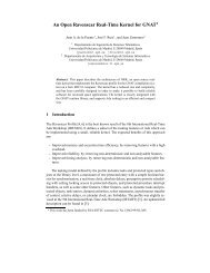
A remote debugger is an extremely useful tool <strong>for</strong> an embedded<br />
system developer. It can drastically decrease development<br />
time. There is no open source <strong>Ada</strong>/C debugging<br />
solution <strong>for</strong> the <strong>NXT</strong>. In this section we describe<br />
a way to remotely debug <strong>Ada</strong>/C programs <strong>for</strong> the <strong>NXT</strong><br />
using the GNU debugger (GDB) and the ARM EmbeddedICE<br />
(In-circuit Emulator) technology. The ARM EmbeddedICE<br />
is a JTAG 4 -based debugging channel available<br />
on the ARM main processor. Debugging the <strong>NXT</strong><br />
from a host computer through the available JTAG interface<br />
is there<strong>for</strong>e possible. RAM and Flash programming<br />
is also available using this method.<br />
This solution has been adapted to work on GNU/Linux<br />
x86 hosts but it could be easily ported to a Windows<br />
plat<strong>for</strong>m.<br />
6.1 Overview<br />
The JTAG-based debugging channel provides real-time<br />
access to memory addresses and data dependent watchpoints,<br />
step-by-step execution, full control of the central<br />
processing unit and other related debugging features. It<br />
requires no use of memory unlike debugging monitor solutions.<br />
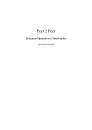
The ARM featured EmbeddedICE-compatible macrocell<br />
from the <strong>NXT</strong> includes an ARM7 core, a small<br />
amount of control logic, a TAP 5 (Test Access Port) controller<br />
<strong>for</strong> the JTAG interface and an EmbeddedICE<br />
macrocell, see figure 7. This EmbeddedICE macrocell has<br />
two real-time watchpoint registers as well as control and<br />
status registers. Each watchpoint register can be configured<br />
as a watchpoint <strong>for</strong> data access or a breakpoint <strong>for</strong><br />
instruction fetch. If a match occurs between the values<br />
programmed into the watchpoint registers and the values<br />
of the address bus and data busses or some specific<br />
control signal, the ARM7 core ceases to read instructions<br />
from the data bus and isolates itself from the memory<br />
system entering debug state. Access to the processor’s<br />
state and memory system is then possible through the<br />
JTAG interface using the TAP controller.<br />
GDB provides the remote serial protocol (RSP) <strong>for</strong> remote<br />
debugging. RSP is a GDB protocol used to send<br />
debugging commands through a serial or ethernet link.<br />
Using a localhost TCP connection on the developer’s host<br />
computer an OpenOCD daemon processes the commands<br />
issued by GDB.<br />
OpenOCD (The Open On-Chip Debugger) is an open<br />
source tool initially developed by Dominic Rath as part<br />
4 JTAG, as defined by the IEEE Std.-1149.1 standard, is an integrated<br />
method <strong>for</strong> testing interconnects on printed circuit boards<br />
(PCBs) that are implemented at the integrated circuit (IC) level.<br />
5 a TAP is the core of the JTAG standard. It is a finite state<br />
machine that controls JTAG operations.
• Wire stripper.<br />
executable<br />
• Soldering iron with a fine tip and solder.<br />
GDB<br />
debugger<br />
RSP protocol via<br />
TCP connection<br />
through localhost<br />
OpenOCD<br />
daemon<br />
• De-soldering pump.<br />
• Magnifying glass.<br />
• Drill with 4 mm diameter bit.<br />
Host PC running with GNU/Linux<br />
EmbeddedICE<br />
macrocell<br />
Control<br />
logic<br />
ARM7 core<br />
TAP controller<br />
<strong>LEGO</strong> <strong>MINDSTORMS</strong> <strong>NXT</strong><br />
ARM7 FTDI macrocell<br />
JTAG protocol<br />
USB protocol<br />
FTDI-based<br />
JTAG adapter<br />
Figure 7: ICE debugging solution <strong>for</strong> <strong>NXT</strong>.<br />
• Digital multimeter.<br />
• 20 pin 2.54 pitch ribbon cable male connector (ARM<br />
JTAG connector).<br />
• 30 SWG single core polyurethane insulated cable.<br />
6.2.3 <strong>NXT</strong> Brick disassembly<br />
Take out the battery pack or batteries to gain access to<br />
the four Philips head screws. Unscrew them and remove<br />
the front cover. Remove the silicon rubber buttons’ assembly.<br />
of his diploma thesis at the University of Applied Sciences<br />
Augsburg [9]. This software provides debugging,<br />
in-system programming and boundary-scan testing <strong>for</strong><br />
embedded targets such as the <strong>NXT</strong>. OpenOCD essentially<br />
allows GDB to talk through a JTAG adapter to<br />
the EmbeddedICE-compatible macrocell on the <strong>NXT</strong>.<br />
A JTAG adapter is a piece of hardware that connects<br />
the host computer with the JTAG interface of the remote<br />
target. The JTAG adapter is in charge of adapting the<br />
serial electric signalling received from OpenOCD, using,<br />
in this case, an FTDI 6 chip, to send the JTAG operations<br />
to the TAP controller. Figure 7 shows the debugging<br />
scheme.<br />
6.2 Modifying the <strong>NXT</strong> Brick<br />
To connect GDB in the host computer with the JTAG<br />
interface of the <strong>NXT</strong> a JTAG adapter is required. Also,<br />
The <strong>NXT</strong> Brick PCB has the provision <strong>for</strong> mounting a<br />
JTAG connector but this has not been mounted to save<br />
cost. The <strong>NXT</strong> Brick must be opened in order to access<br />
the JTAG interface. Note that by per<strong>for</strong>ming this<br />
modification warranty will be lost.<br />
6.2.1 FTDI-based JTAG adapter<br />
An FTDI-based JTAG adapter that is both compatible<br />
with OpenOCD and the main processor of the <strong>NXT</strong><br />
(AT91SAM7S256) is required. For this guide the ARM-<br />
USB-TINY-H adapter by Olimex (http://www.olimex.<br />
com) was used. Open On-Chip Debugger: OpenOCD<br />
<strong>User</strong>’s <strong>Guide</strong> [10] offers other vendor options.<br />
6.2.2 Tools and materials<br />
• Small Philips head screwdriver.<br />
• Fine wire cutter.<br />
6 Hardware solution to interface with USB peripherals.<br />
Figure 8: <strong>NXT</strong> without front cover.<br />
Find the two screws, that hold down the LCD display,<br />
located on each side of it (the two small squares of figure<br />
8). Loosen these screws and carefully lift the LCD display<br />
to get access to the battery terminals that are soldered<br />
to the main PCB. Note that the LCD display cannot be<br />
removed from the PCB board on some models.<br />
Once the two display screws have been removed the<br />
two battery terminals must be de-soldered (the two small<br />
circles of figure 8). To do this, remove the solder with<br />
the soldering iron and the de-soldering pump. When the<br />
terminals are free of solder separate the PCB from the<br />
battery case and remove the input and output connector<br />
supports. Note that there is a small silicone rubber pushbutton<br />
between the battery case and the PCB.<br />
6.2.4 JTAG connection<br />
Since there was no short delivery 1.27 pitch connectors<br />
at the time, The hard-wired option presented below was<br />
used.<br />
Cut 8 equal lengths, at least 100 mm, of the single core<br />
cable and strip 3 mm of insulation on one side. Identify<br />
both ends with an indelible marker. The JTAG interface<br />
(J17 on the PCB) is located below the loudspeaker beside<br />
the quartz crystal (the big square of figure 8). Pin 1 has
a square pad and the remaining pins have round pads.<br />
Insert one by one the stripped ends of the 8 cables in<br />
pins 1 - 8 and solder them to the board. This type of<br />
wire is used because, unlike PVC insulation, it supports<br />
high temperatures (155 o C) and makes soldering easy.<br />
With the magnifying glass inspect each solder <strong>for</strong> bridges<br />
between pins. See left picture from figure 9 <strong>for</strong> the final<br />
result.<br />
Figure 9: Soldered JTAG interface & front cover drilled<br />
hole.<br />
Drill a 4 mm hole on the front cover of the <strong>NXT</strong> Brick<br />
directly above the J17 connection as shown in the right<br />
picture of figure 9. As a strain relief bundle the eight<br />
wires together and tie a knot with them 20 mm from<br />
the PCB. Take them through the hole of the front cover<br />
and cut them to length <strong>for</strong> the connection to the ribbon<br />
cable connector according to figure 10. As the wire used<br />
has a smaller gauge than the connector it is advisable to<br />
solder the connections after inserting them. There<strong>for</strong>e,<br />
strip the wires, insert them and solder them. Try to use<br />
as little solder as possible to allow inserting the header in<br />
the connector.<br />
R89<br />
10K<br />
TP86<br />
R90<br />
10K<br />
TP85<br />
VCC 3V<br />
GND<br />
GND<br />
GND<br />
GND<br />
GND<br />
GND<br />
GND<br />
GND<br />
GND<br />
RA4D<br />
10K<br />
TP82<br />
RA4C<br />
10K<br />
TP83<br />
20 pin ribbon cable connector<br />
(ARM JTAG connector)<br />
2 1<br />
4 3<br />
6 5<br />
8 7<br />
10 9<br />
12 11<br />
14 13<br />
16 15<br />
18 17<br />
20 19<br />
RA4B<br />
10K<br />
TP84<br />
RA4A<br />
10K<br />
VCC 3V<br />
PULL UP 10K<br />
TDI<br />
TMS<br />
TCK<br />
TCK<br />
TDO<br />
NRST<br />
TCK<br />
TMS<br />
TDO<br />
NRST<br />
TDI<br />
GND<br />
PULL UP 10K<br />
VCC 3V<br />
J17<br />
1<br />
2<br />
3<br />
4<br />
5<br />
6<br />
7<br />
8<br />
Small connector<br />
single row, 1,27 pitch<br />
6.2.5 Testing the connections<br />
Locate on the <strong>NXT</strong> Brick PCB resistor R89, check <strong>for</strong><br />
continuity with the multimeter in Ω between the top of<br />
R89 and pin 2 of the ribbon cable connector (VCC 3V).<br />
Check that the other end of R89 is connected to pin 3<br />
of the ribbon cable connector (PULL UP 10K). Next,<br />
check the GND connection between pin 6 of the ribbon<br />
cable connector and the negative battery terminal PCB<br />
connection (J5). Locate test points TP82 - TP86 on the<br />
solder side of the PCB and check with the multimeter <strong>for</strong><br />
continuity between them and the corresponding pins of<br />
the ribbon cable connector. Also check <strong>for</strong> short-circuits<br />
between connections.<br />
Finally, once the connections have been checked, reassemble<br />
the <strong>NXT</strong> Brick.<br />
For a more graphical guide on the modification of the<br />
<strong>NXT</strong> Brick refer to Installing the JTAG connector [11].<br />
6.3 A debugging session<br />
In order to remotely debug programs under GNU/Linux<br />
libusb-0.1, libusb-dev, libftdi1 and libftdi-dev<br />
are required. The FTDI module with the JTAG adapter<br />
in<strong>for</strong>mation will probably have to be loaded also, once it<br />
is plugged in:<br />
$ sudo modprobe -v ftdi_sio<br />
vendor=0x... product=0x...<br />
When the <strong>NXT</strong> has no firmware the orange button must<br />
be pressed. Then, when a clicking sound is heard,<br />
the JTAG adapter must be plugged to the <strong>NXT</strong>. Next,<br />
arm-eabi-openocd must be run with a specific configuration<br />
script:<br />
$ arm-eabi-openocd -f debug-ram.cfg<br />
This configuration file is a setup <strong>for</strong> OpenOCD that establishes<br />
communications with the <strong>NXT</strong> EmbeddedICE<br />
macrocell. The script usually contains the daemon configuration<br />
that establishes communications with GDB, the<br />
configuration <strong>for</strong> the adapter, the board, the target and<br />
some init commands. JTAG adapter vendors usually provide<br />
this OpenOCD script and in case they do not, the<br />
share/openocd/scripts folder from the install directory<br />
contains generic configuration files. For further in<strong>for</strong>mation<br />
refer to Open On-Chip Debugger: OpenOCD <strong>User</strong>’s<br />
<strong>Guide</strong> [10].<br />
When OpenOCD handshakes with the <strong>NXT</strong> successfully<br />
GDB must be run with the executable as parameter,<br />
not with the binary image:<br />
Figure 10: <strong>NXT</strong> JTAG hardware schematic.<br />
Note that the GND connection is only connected to pin<br />
6 because the JTAG adapter used has all the GND pins<br />
internally connected.<br />
$ arm-eabi-gdb executable_name<br />
Any breakpoints should be added at this point. After,<br />
the gdbinit script, see listing 2, must be run:
gdb> source gdbinit<br />
Cross-debugging is now possible.<br />
Listing 2: GDB init script<br />
# Init command<br />
target remote localhost:3333<br />
# OpenOCD command to halt the processor<br />
# and wait<br />
monitor soft_reset_halt<br />
# OpenOCD command to select the core state<br />
monitor arm core_state arm<br />
# set flash wait state (AT91C_MC_FMR)<br />
monitor mww 0xffffff60 0x00320100<br />
# watchdog disable (AT91C_WDTC_WDMR)<br />
monitor mww 0xfffffd44 0xa0008000<br />
# enable main oscillator (AT91C_PMC_MOR)<br />
monitor mww 0xfffffc20 0xa0000601<br />
# wait 100 ms<br />
monitor sleep 100<br />
# set PLL register (AT91C_PMC_PLLR)<br />
monitor mww 0xfffffc2c 0x00480a0e<br />
# wait 200 ms<br />
monitor sleep 200<br />
# set master clock to PLL (AT91C_PMC_MCKR)<br />
monitor mww 0xfffffc30 0x7<br />
# wait 100 ms<br />
monitor sleep 100<br />
# enable user reset AT91C_RSTC_RMR<br />
monitor mww 0xfffffd08 0xa5000401<br />
# <strong>for</strong>ce a peripheral RESET AT91C_RSTC_RCR<br />
monitor mww 0xfffffd00 0xa5000004<br />
# toggle the remap register to place RAM<br />
# at 0x00000000<br />
monitor mww 0xffffff00 0x01<br />
# set the PC to 0x00000000<br />
monitor reg pc 0x00000000<br />
# enable use of software breakpoints<br />
monitor gdb_breakpoint_override soft<br />
monitor arm7_9 dbgrq enable<br />
# upload the application<br />
load<br />
# resume execution from reset vector<br />
continue<br />
This GDB script basically sets the ARM processor to execute<br />
the application and set some debugging features.<br />
The script used is a modified version of that presented in<br />
Using Open Source Tools <strong>for</strong> AT91SAM7S Cross Development<br />
by James P. Lynch [12].<br />
7 Conclusions<br />
This guide shows the basics <strong>for</strong> <strong>Ada</strong> development using<br />
<strong>LEGO</strong> <strong>MINDSTORMS</strong> <strong>NXT</strong>. The Ravenscar profile runtime<br />
system offers concurrency <strong>Ada</strong> programming while<br />
making possible a schedulability analysis of the system.<br />
<strong>Ada</strong> development on the <strong>NXT</strong> presents a whole perspective<br />
of an embedded system with real-time constraints.<br />
At a reasonable price the <strong>NXT</strong> kit offers all kinds of<br />
sensors and mechanisms to work with, even custom-made<br />
sensors can be developed.<br />
Development and sharing of <strong>Ada</strong> projects with the<br />
<strong>NXT</strong> would be of great interest, in the same way as other<br />
complex models like Rubik’s cube solvers, Segway robots,<br />
scanners, etc. have been developed using other programming<br />
languages and shared.<br />
The <strong>Ada</strong> community is encouraged to use this development<br />
plat<strong>for</strong>m that, besides the fun, can be an interesting<br />
teaching asset.<br />
It is important to note that all of the tools used,<br />
except LDD, are open source and there<strong>for</strong>e there is no<br />
dependance on software vendors. All of the source code<br />
is available and can by modified.<br />
Acknowledgements<br />
The authors would like to thank <strong>Ada</strong>Core <strong>for</strong> their<br />
work adapting the Ravenscar run-time system and developing<br />
the <strong>Ada</strong> drivers <strong>for</strong> the <strong>LEGO</strong> <strong>MINDSTORMS</strong><br />
<strong>NXT</strong> plat<strong>for</strong>m.<br />
References<br />
[1] Burns A, Dobbing B, Vardanega T. <strong>Guide</strong> <strong>for</strong> the<br />
use of the <strong>Ada</strong> Ravenscar Profile in high integrity<br />
systems. <strong>Ada</strong> Lett. 2004 June;XXIV:1–74. Available<br />
from: http://doi.acm.org/10.1145/997119.<br />
997120.<br />
[2] <strong>LEGO</strong>. <strong>LEGO</strong> <strong>MINDSTORMS</strong> <strong>NXT</strong> Hardware Developer<br />
Kit;. Version 1.00. Available from: http:<br />
//mindstorms.lego.com.<br />
[3] <strong>LEGO</strong>. <strong>LEGO</strong> <strong>MINDSTORMS</strong> <strong>NXT</strong> ARM7 Bluetooth<br />
Developer Kit;. Version 1.00. Available from:<br />
http://mindstorms.lego.com.<br />
[4] <strong>Ada</strong>Core. GNAT Pro <strong>User</strong>’s <strong>Guide</strong>, Supplement <strong>for</strong><br />
High-Integrity Edition Plat<strong>for</strong>ms; 2011. The GNAT<br />
<strong>Ada</strong> Compiler. GNAT GPL Edition, Version 2011<br />
Document revision level 175263.
[5] Std. 8652:1995/Amd 1:2007 — <strong>Ada</strong> 2005 Reference<br />
Manual. Language and Standard Libraries;<br />
2007. Published by Springer-Verlag, ISBN 978-3-<br />
540-69335-2.<br />
[6] de la Puente JA, Ruiz JF, Zamorano J. An Open<br />
Ravenscar Real-Time Kernel <strong>for</strong> GNAT. In: Proceedings<br />
of the 5th <strong>Ada</strong>-Europe International Conference<br />
on Reliable Software Technologies. <strong>Ada</strong>-<br />
Europe ’00. London, UK: Springer-Verlag; 2000. p.<br />
5–15. Available from: http://portal.acm.org/<br />
citation.cfmid=646579.697613.<br />
[7] Bradley PJ, de la Puente JA, Zamorano J. Real-time<br />
system development in <strong>Ada</strong> using <strong>LEGO</strong> MIND-<br />
STORMS <strong>NXT</strong>. In: Proceedings of the ACM<br />
SIG<strong>Ada</strong> annual international conference on SIG<strong>Ada</strong>.<br />
SIG<strong>Ada</strong> ’10. New York, NY, USA: ACM; 2010. p.<br />
37–40. Available from: http://doi.acm.org/10.<br />
1145/1879063.1879077.<br />
[8] <strong>LEGO</strong>. <strong>LEGO</strong> Digital Designer 4.1 <strong>User</strong> Manual;<br />
2011. Available from: http://ldd.lego.com.<br />
[9] Rath D. Open On-Chip Debugger. Design and Implementation<br />
of an On-Chip Debug Solution <strong>for</strong> Embedded<br />
Target Systems based on the ARM7 and<br />
ARM9 Family. University of Applied Sciences Augsburg;<br />
2005.<br />
[10] Brownell D. Open On-Chip Debugger: OpenOCD<br />
<strong>User</strong>’s <strong>Guide</strong>; 2011. Available from: http://<br />
openocd.berlios.de.<br />
[11] IAR. Installing the JTAG connector. IAR Kick-<br />
Start <strong>for</strong> <strong>LEGO</strong> <strong>MINDSTORMS</strong> <strong>NXT</strong>; 2009. Available<br />
from: http://www.iar.com/website1/1.0.1.<br />
0/1483/1.<br />
[12] Lynch JP. Using Open Source Tools <strong>for</strong> AT91SAM7S<br />
Cross Development. Grand Island, New York, USA;<br />
2007. Revision C.