KRYOCLIM gb janvier 2004 - Glynwed A/S
KRYOCLIM gb janvier 2004 - Glynwed A/S
KRYOCLIM gb janvier 2004 - Glynwed A/S

You also want an ePaper? Increase the reach of your titles
YUMPU automatically turns print PDFs into web optimized ePapers that Google loves.
<strong>KRYOCLIM</strong> ®<br />
SYSTEM<br />
PIPES AND FITTINGS<br />
for cold applications<br />
Centralised AIR CONDITIONING<br />
Secondary REFRIGERATION<br />
ISSUE<br />
JANUARY <strong>2004</strong><br />
TECHNICAL<br />
DOCUMENTATION<br />
safety for your pipeworks
<strong>KRYOCLIM</strong> ® SYSTEM<br />
<strong>2004</strong><br />
TECHNICAL DOCUMENTATION<br />
SUMMARY<br />
Technical Sheet<br />
0.0<br />
Titles<br />
• Summary 0.0<br />
General characteristics<br />
• Applications 1.1<br />
• Benefits 1.2<br />
• Characteristics 1.3<br />
• Operating conditions 1.4<br />
n° Technical Sheets<br />
Range<br />
• Descriptive 2.1<br />
Works on pipes and fittings<br />
• Tools 3.1<br />
• Cold welding method 3.2<br />
• Recommendations 3.3<br />
• Control, testing and implementation 3.4<br />
Contraction Expansion<br />
• Phenomenon - calculations 4.1<br />
• Consequences 4.2<br />
• Remedies 4.3<br />
• Determining of leg B 4.4<br />
• Expansion joints 4.5<br />
Environnement<br />
• MONOKLIP brackets 5.1<br />
• Basket tray for insulated pipes 5.2<br />
• Insulation 5.3<br />
• Antifreeze fluids 5.4<br />
Pressure losses<br />
• Calculation rules 6.1<br />
• Diagram at 7°C 6.2<br />
Dimensional sheets<br />
• Usual pipes and fittings 7.1 to 7.5<br />
Compatible fluids<br />
• Antifreeze fluids 8.0<br />
• Chemical resistance tables 8.1 to 8.7<br />
IMPORTANT DETAIL : The date on cach page of this documentation is not a printing date but an updating date.
<strong>KRYOCLIM</strong> ® SYSTEM<br />
GENERAL CHARACTERISTICS<br />
APPLICATIONS<br />
Technical Sheet<br />
1.1<br />
<strong>2004</strong><br />
GIRPI is a part of an international group present in many countries (Aliaxis).<br />
Thanks to its long experience in the fields of refrigeration and air conditioning with its different<br />
products, GIRPI developed a complete system which answers the needs of the following applications<br />
:<br />
• Centralised Air conditioning applications :<br />
- chilled water<br />
• Industrial applications :<br />
- cooling<br />
- process<br />
• Food industry<br />
- refrigerated warehouses<br />
- industrial kitchens<br />
<strong>KRYOCLIM</strong> ® benefits from the low temperature performance of its main component called HPF.<br />
The system is particulary suitable for commercial and industrial secondary refrigeration and indirect<br />
air conditioning applications.<br />
Thanks to its wide range of pipes (diameter 20 to 160), fittings and accessories especially developed<br />
to be adapted to existing networks, <strong>KRYOCLIM</strong> ® enables the installation of every kind of commercial<br />
and industrial refrigeration and indirect air conditioning networks from -30° to +40° C based<br />
on the following secondary fluids : chilled water, gylcols...<br />
The practice, which is well known in centralised air conditioning applications is being chosen<br />
more and more for complete commercial and industrial refrigeration applications.
<strong>KRYOCLIM</strong> ® SYSTEM<br />
2000<br />
GENERAL CHARACTERISTICS<br />
BENEFITS<br />
Technical Sheet<br />
1.2<br />
The <strong>KRYOCLIM</strong> ® system offers a lot of benefits against traditional materials :<br />
❏ Corrosion resistant :<br />
❏ Strength-Impact Resistant :<br />
❏ Fire classification :<br />
❏ Non-permeability :<br />
❏ Hydraulicity :<br />
❏ Thermal conductivity<br />
cœfficient :<br />
❏ Condensation :<br />
❏ Chemical resistance :<br />
❏ Installation :<br />
<strong>KRYOCLIM</strong> ® is non-corrodible and allows to avoid<br />
expensive film-forming treatments. The networks<br />
remained perfectly sealed.<br />
The <strong>KRYOCLIM</strong> ® manufactured of HPF ® alloy withstands<br />
impact even at low temperature.<br />
The <strong>KRYOCLIM</strong> ® system is non-flammable and is<br />
being classified M1<br />
<strong>KRYOCLIM</strong> ® is non-permeable to oxygen, thus eliminating<br />
the formation of sludge inside the pipes.<br />
The smooth internal surface of <strong>KRYOCLIM</strong> ® products<br />
reduces frictional losses.<br />
Energy savings.<br />
Fall of the heat losses up to 30 % in comparison with<br />
steel.<br />
Reduced problems against traditional materials. The<br />
external temperature of <strong>KRYOCLIM</strong> ® pipes is several<br />
degrees higher.<br />
<strong>KRYOCLIM</strong> ® has been developed to have a perfect<br />
compatibility with the fluids presented in the sheet<br />
8.0.<br />
Easy- to-install system<br />
- Light weight.<br />
- Simple tools.<br />
- No flame.<br />
The <strong>KRYOCLIM</strong> ® system can be built-in, embedded<br />
or buried.
<strong>KRYOCLIM</strong> ® SYSTEM<br />
GENERAL CHARACTERISTICS<br />
Technical Sheet<br />
1.3<br />
2000<br />
1. PHYSICAL CHARACTERISTICS<br />
Characteristics Standards Units Values<br />
Physical aspect NF T 54-029 - ISO 7686 — —<br />
Fire classification<br />
M1-being classified<br />
Volumic mass NF T 54-022 - ISO 1183/3514 kg/m 3 ≈ 1350<br />
Linear expansion dilation ASTM D 696-70 mm/m °C 0,09<br />
Transversal vesistivity (under 1000 V) ASTM D 257/76 Ohm.cm 10 15<br />
Termal conductivity λ ASTM C 177-76 W/m°C 0,17<br />
Shrinkage at 150°C NF T 54.021 - ISO 2505 % ≤ 4<br />
2. MECHANICAL CHARACTERISTICS<br />
Characteristics Standards Units Values<br />
Bending under load NF T 51-005/méth.A - ISO 877<br />
temperature<br />
°C ≈ 55<br />
VICAT softening temperature NF T 51-021/méth.B - ISO R 306<br />
(5 daN load) NF T 54-034 - ISO 2056/2507<br />
°C ≥ 75<br />
Resistance to static pressure NF T 54 035 - ISO 2035 —<br />
• at 20°C time ≥ 1 h NF T 54-016 — 4,2 x PN<br />
Resistance to alternating pressure NF T 54-094<br />
(on fittings and glued jointings) NF T 54-016<br />
Pressure : min 20 bar/max. 60 bar<br />
• ø 20 to 90 : frequency 1Hz Cycles ≥ 5000<br />
• ø 110 : frequency 0,42 Hz Cycles ≥ 2500<br />
1 MPa = 10 bars<br />
3. QUALITY CONTROLS<br />
To provide a normal quality level for ist products and to guarantee its users that the stated performances are respected,<br />
GIRPI has implemented the control regulations imposed by the different French and international standards.<br />
The controls concern the physical and mechanical characteristics of the couplings.<br />
However in addition to the above verifications and to guarantee the maximum reliability level in actual operating<br />
conditions, GIRPI has developed and carries out additional tests one of which is currently undergoing standardization<br />
(NF T 54-094 standard).<br />
Thus, a crushing operation on the couplings associated with an alternate pressure test (on solvent cement fittings<br />
assemblies) is regulary carried out. The couplings are subjected to fluid hammer cycles (20/60 bar) at 3600<br />
cycles/hour for diameters 20 to 90 and 1500 cycles/hour for diameters 110 and 160.<br />
Furthermore, operational test are constantly carried out on our laboratory’s testing rigs. This enables us to guarantee<br />
the adaption of each component in the pipework to its own function.<br />
The ISO 9001 Version 2000 certified procedures at all stages (production, quality, control etc...) guarantee globally<br />
the quality of GIRPI’s products.
<strong>KRYOCLIM</strong> ® SYSTEM<br />
2000<br />
GENERAL CHARACTERISTICS<br />
OPERATIONS CONDITIONS<br />
Technical Sheet<br />
1.4<br />
WORKING PRESSURE AND TEMPERATURE<br />
10 bar from - 30°C to + 20°C<br />
(PMS)<br />
10 bars<br />
MAXIMUM WORKING<br />
PRESSURE<br />
The flow temperature of some networks (such as process or<br />
defreezing of convection fans) can reach more than 20°C.<br />
<strong>KRYOCLIM</strong> ® allows a maximum temperature of 40°C with a<br />
maximum pressure of 7 bar.<br />
7 bars<br />
Fluid Température<br />
temperature<br />
du fluide<br />
■ WORKING LIFETIME :<br />
-30 -20 -10 0 10 20 30 40 (°C)<br />
The working pressure and temperature indicated in the following tables are determined for a working life of 50<br />
years without interruption.<br />
Working pressures according to working temperatures are figured out by using regression curves as per standard<br />
NF T 54-091.<br />
■ TESTING PRESSURE<br />
PN<br />
Testing pressure<br />
1 hour (20°C)<br />
4,2 PN<br />
10 42 bars<br />
2,5 PN<br />
1 heure 100 h 1000 h 10 000 h 50 ans<br />
A pressure pipework can be classified as PN 10 (with a safety factor of 2.5 after 50 years) if it can tolerate, during<br />
one hour, a pressure equal to 4.2 times this PN. The characteristics of the system can only be guaranteed to 50<br />
years by combining these two parameters.<br />
The readings for the breaking pressures for <strong>KRYOCLIM</strong> ® change, as shown in a straight-line in logarithmic co-ordinates.<br />
Considering the safety cœfficients, the pressure ratio between 50 years and one hour ranges from 4.2 to 2.5. This<br />
straight line is drawn on the basis of the 1 hr, 100 hr, 1000 hr and 10,000 hr tests, and is then extrapolated to 50<br />
years.<br />
■ GARANTIES :<br />
• For all applications specified in the technical documentation, regardless of pipe diameter, GIRPI has an insurance<br />
to guarantee installations which are carried out in accordance with its own general recommendations, and which<br />
respect the temperature and pressure conditions and the nature of fluid specified above.
<strong>KRYOCLIM</strong> ® SYSTEM<br />
Technical Sheet<br />
RANGE<br />
2.1<br />
2000<br />
Description<br />
Ref.<br />
Diameters in mm<br />
20 25 32 40 50 63 75 90 110 160<br />
<strong>KRYOCLIM</strong> ® pipe TUB F ● ● ● ● ● ● ● ● ● ●<br />
SOCKETS FMA ● ● ● ● ● ● ● ● ● ●<br />
Description<br />
Réf.<br />
ADAPTOR NIPPLES FEAL 1/2” 3/4”<br />
BRASS THREADED<br />
Diameters in mm<br />
20 25 32 40 50 63 75<br />
ELBOWS 90° F4M ● ● ● ● ● ● ● ● ● ●<br />
ADAPTOR NIPPLES FEA 1” 1”1/4 1”1/2 2” 2”1/2<br />
ELBOWS 45° F8M ● ● ● ● ● ● ● ● ● ●<br />
THREADED ADAPTORS FMML 1/2” 3/4” 1”<br />
Female brass<br />
thread<br />
EQUAL TEES FTE ● ● ● ● ● ● ● ● ● ●<br />
THREADED ADAPTORS FMM 1”1/4 1”1/2 2” 2”1/2<br />
Female thread<br />
CAPS FBO ● ● ● ● ● ● ● ● ● ●<br />
ACCESSORIES<br />
REDUCING BUSHES FRS 20 25 32 40 50 63 75 90<br />
SHORT ● ● ● ● ● ● ● ●<br />
REDUCING BUSHES FRD 20 20 32 25 40 50 110<br />
LONG 25 32 40 50 63<br />
40 50 63 75<br />
SERRATED STUB FCS ● ● ● ● ● ●<br />
FLANGES<br />
FLANGES BPA ● ● ● ● ● ●<br />
BVR<br />
REDUCED TEES FTR 20 20 20 20 20 20<br />
25 25 25 25 25 25 32<br />
32 32 32<br />
40 40 40 40 50<br />
3 PIECE UNIONS F3P ● ● ● ● ●<br />
PLAIN NIPPLES FMC<br />
M/M<br />
lenght (mm)<br />
37 42 49 57 67 80<br />
3 PIECE F3G/L 1/2” 3/4” 1” 1”1/4 1”1/2 2”<br />
UNIONS<br />
F Brass<br />
3 PIECE F3F/L 1/2” 3/4” 1” 1”1/4 1”1/2 2”<br />
UNIONS<br />
M Brass<br />
Description<br />
Ref.<br />
Diameters in mm<br />
20 25 32 40 50 63 75 90 110<br />
FLAT GASKET JPN ● ● ● ●<br />
CEMENT<br />
CLEANER<br />
1 l<br />
HPFIXP<br />
HPFIXB<br />
D171P<br />
MONOKLIP HCK(C) ● ● ● ● ● ●<br />
BRACHETS A9C ● ● ●<br />
+ Wedge h t = 20mm CALE ● ● ● ● ● ●<br />
BASKET TRAY GIRFIL 200 300 400<br />
(For insulated<br />
networks).<br />
ACCESSORIES FOR<br />
BASKET TRAY<br />
• Hanging clip FATT ● ● ●<br />
• Kit (4 bolts + FILKIT ● ● ●<br />
2 splices + 4 clamps)<br />
• CLIPS SUPPORT FSUP ● ●<br />
EXPANSION JOINTS<br />
• Sochet threadet HCD/G 1/2” 3/4” 1”<br />
+ free nut<br />
• 2 brass threaded ends HCD/L 3/4” 1” 1”1/4 1”1/2 2”<br />
ANTIFREEZE FLUIDS NEUTRAGEL ®<br />
* on request<br />
MIXIGEL ®<br />
*
<strong>KRYOCLIM</strong> ® SYSTEM<br />
2000<br />
WORKS ON PIPES AND FITTINGS<br />
TOOLS<br />
Technical Sheet<br />
3.1<br />
■ CUTTING<br />
• The roller plastic pipe-cutter Réf. GIRPI CT1240 Ø 12 to 40 mm<br />
Réf. GIRPI CT1263 Ø 12 to 63 mm<br />
Réf. GIRPI CT50110 Ø 50 to 110 mm<br />
• The chamfering pipe-cutter<br />
This tool cuts and chamfers the pipe after cutting, in one single operation. It is designed<br />
to cut the Ø 160 pipes without accessories.<br />
Réf. GIRPI CTC63<br />
Réf. GIRPI CTC110<br />
Ø 32 to 63 mm<br />
Ø 75 to 110 mm<br />
■ TRIMMING - CHAMFERING<br />
After cutting, the pipe must be trimmed inside and a chamfer must be made<br />
on the outside.<br />
These operations can be performed by means of a 1/2-round bastard file.<br />
IMPORTANT<br />
• Trimming and chamfering cone : This tool can be used on the pipe, on the other side it chamfers the outside.<br />
Réf. GIRPI CONE 50 U for pipes Ø 12 to 50 mm.<br />
Chamfering pipe-cutter See cutting section.<br />
Chamfering tool<br />
This tool chamfers the pipe outside<br />
from Ø 50 to Ø 160.<br />
Réf. GIRPI CHANF160<br />
Trimmer<br />
This reams the inside of pipes of all diameters.<br />
Réf. GIRPI EBAV1 Ø 12 à 160 mm<br />
■ HOLDING TOOLS<br />
Chain vice *<br />
Polyurethane pipe-rests hold the pipe without<br />
any scratching.<br />
Strap wrench *<br />
Maximum gripping power, with no risk of deforming the pipes<br />
or fittings (braided nylon strap).<br />
pipe-rest<br />
Chain bench vice *<br />
Vice (traditionnal) In this case all the necessary precautions must be taken so that the pipe is neither crushed nor scratched<br />
by the jaws. For this purpose, a “hard wood tool” can be cheaply produced. The pipe should be placed in the corresponding<br />
notch ; by tightening up the vice the tool clamps the pipe.<br />
* Thes tools are distributed (among other sellers) by Ets AGI - 75, rue St-Denis - 93300 Aubervilliers - France - Tél. 01 48 34 91 99.
<strong>KRYOCLIM</strong> ® SYSTEM<br />
WORKS ON PIPES AND FITTINGS<br />
TOOLS<br />
Technical Sheet<br />
3.2.1<br />
<strong>2004</strong><br />
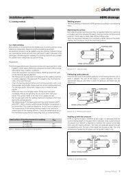
CUTTING CHAMFERING BONDING ASSEMBLY<br />
■ CHEKS PRIOR BEFORE BONDING<br />
The operation of abrading and cleaning are canceled.<br />
Before bonding, it is important to make certain checks : the pipes must be clean and dry. The working zone is clean,<br />
otherwise it is necessary to clean the pipes and the fittings with a cleancloth, or even D 171 cleaner.<br />
IMPORTANT<br />
- Water impairs the cement and subsequently the welding quality. No cold welding will therefore be<br />
applied if the parts to be assembled are damp (prior drying).<br />
- With HPFIX the assembly can be made when the temperature is over +5°C and under +35°C, these are<br />
mandatory limits.<br />
- The atmospheric conditions (temperature, humidity) considerably affect the setting time (drying,<br />
evaporation of solvents) of the cement.<br />
- At low temperature, the parts when assembled should be held together for 20 to 30 seconds.<br />
- In hot weather, the cement should be applied rapidly and the parts immediately jointed.<br />
- So as to avoid evaporation of the solvent contained in the cement, the pot must be closed after each cold<br />
welding operation.<br />
■ MARKING OF THE SOCKET LENGTH<br />
- It is useful, in the case of the pipe, to trace on it (using a thick pencil or felt marker) a mark at a<br />
distance equal to the corresponding socket depth.<br />
Mark<br />
This mark enables:<br />
1) applying the cement over the necessary length<br />
2) checking whether the penetration length of the male end in the socket is correct.
<strong>KRYOCLIM</strong> ® SYSTEM<br />
2000<br />
GENERAL CHARACTERISTICS<br />
WELDING PROCEDURE<br />
Technical Sheet<br />
3.2.2<br />
■ COLD WELDING<br />
- When the checks and marking have been done, then apply the cement.<br />
- HPFIX cement must be employed.<br />
Do not use any other cement.<br />
- To apply the cement, use a suitable brush. Do not use: your fingers, a piece of wood or any other utensil; dipping<br />
the pipe or couplings in the cement is prohibited (this way of doing things creates a bead of cement at the bottom<br />
of the socket and in small diameters a film obstructing the bore).<br />
- Apply the cement moderately (in a thin coat) over the whole (the female) interlock length and over the whole length<br />
of the male end (marked on pipe). The cement should be applied in 2 thin cross-coats, the second coat being<br />
in the longitudinal direction. See NF T 54-035 standard. For surfaces with a large diameter, use a brush large<br />
enough.<br />
Cement<br />
Marks<br />
Chamfer<br />
Paint brush<br />
direction<br />
Owing to the standardized tolerance ranges of the male ends and the sockets, some gap may appear.<br />
In this case, double quantities of cement must be applied. This consists in coating the male end once, then the<br />
socket and the male end a second time, then jointing them.<br />
■ JOINTING<br />
Immediately after applying the cement, joint the two elements right home (as far as the marks previously traced)<br />
pushing longitudinally and, above all, without twisting. For surface with a large diameter, two people must be present<br />
in order to assemble the fittings (an operator glues the socket part while the other operator glues the spigot<br />
part.<br />
Mark<br />
Positioning<br />
mark<br />
NB: In certain cases it is necessary to mark the position of one element in relation to the other (see sketch above).<br />
This mark should be done before scouring.<br />
- After jointing and in the case of surplus cement featured by a bead of cement, it is necessary to reduce it without<br />
completely eliminating the trace of cement. This bead should be reduced using a clean cloth or cotton wool.
<strong>KRYOCLIM</strong> ® SYSTEM<br />
WORKS ON PIPES AND FITTINGS<br />
RECOMMENDATIONS - DETERMINING<br />
CEMENT AND CLEANER QUANTITIES<br />
Technical Sheet<br />
3.3<br />
<strong>2004</strong><br />
■ DRYING TIME<br />
With HPFIX cement, the drying times before pressure tests are the following :<br />
Ø (in mm) 20 - 63 75 - 110 160<br />
Ambient<br />
for 6 bar pressure test,<br />
temperature at 20°C<br />
5 to 10°C 2 h 4 h 24 h<br />
11 to 35°C 1 h 2 h 24 h<br />
■ HANDLING AND STORAGE<br />
Like all building materials, the final quality of the installation depends on the conditions in which they are transported,<br />
handled and stored. The pipes and fittings will be stored separately on an even area, away from dust and<br />
the sun. In all cases, take special care to avoid rough handling, impacts and especially with projecting, cutting or<br />
heavy objects, particularly in cold weather.<br />
■ THERMOFORMING<br />
Thermoforming of the <strong>KRYOCLIM</strong> ® pipes is strictly prohibited on the work site and involves cessation of the GIRPI<br />
guarantee. For all changes in direction, make use of standard <strong>KRYOCLIM</strong> ® fittings only. In case of force majeure,<br />
the fabrications will be made in the workshop, without direct flame heating and according to the indications to be<br />
requested in writing from GIRPI.<br />
■ CONNECTIONS OF THE CPVC FITTINGS ONTO THREADED OR TAPPED METAL COMPONENTS<br />
The fittings with screwed or threaded brass inserts molded from a casting : HMML, HEAL, HEBL, H4GL, H4GP<br />
must be used for strong tightening torques on metallic fittings. The waterproofing may be then carried out by traditional<br />
means, except for anaerobic resins.<br />
Excluding connection to wall brackets (GAAP reference), obtained by means of tap connectors (HDR reference),<br />
connections of the CPVC to metal pipes, fittings and equipment, whether tapped or threaded (tapered or<br />
cylindrical), must be made by means of CPVC/metal couplings provided for this purpose.<br />
If sockets, elbows, tees or other <strong>KRYOCLIM</strong> ® fittings are used with the original tapping or threading in the material<br />
itself, they will be screwed by hand, only the last quarter turn if necessary will be made preferably by strap wrench.<br />
In this case, in order to seal tight, the use of tow or a similar material or anaerobic resin is forbidden, as excessive<br />
tightening may provoke irremediable damages.<br />
To obtain this, use:<br />
- Teflon tape type sealing materials, such as GEB’s high density. On male threads, apply 5 layers of<br />
Teflon tape clock wise, starting from 1 st thread;<br />
- Silicone paste (JS 533 by Loctite or Filetplast by GEB). Drying time: 24h. For Ø 1/2" and 3/4", drying<br />
times of 3 hours are sufficient.<br />
In no case should the <strong>KRYOCLIM</strong> ® pipes and fittings be machine-threaded inside or outside.<br />
■ APPROXIMATIVE QUANTITIES FOR 100 JOINTINGS DEPENDING ON PIPE DIAMETER<br />
PIPE Ø<br />
QUANTITY<br />
Welding polymer<br />
20 60 ml<br />
25 - 32 200 ml<br />
40 - 50 0,5 liter<br />
63 - 75 1,5 liters<br />
90 - 110 3 liters<br />
160 6 liters
<strong>KRYOCLIM</strong> ® SYSTEM<br />
2000<br />
INSPECTIONS, TESTS AND PUTTING<br />
INTO SERVICE<br />
Technical Sheet<br />
3.4<br />
■ GENERAL<br />
The <strong>KRYOCLIM</strong> ® system pipes and fittings are inspected throughout their manufacture and are guaranteed for a<br />
use complying with their design within the limits indicated.<br />
During the installation and before putting the <strong>KRYOCLIM</strong> ® network into service, it is advisable to make a certain<br />
number of checks as with all the other materials.<br />
■ INSPECTION<br />
a) Visual inspection<br />
When assembling, the pipes and fittings should be inspected so as to eliminate doubtful elements containing<br />
abnormalities such as impacts or deep scores caused by unsuitable handling. Before the tests, the whole network<br />
will be visually inspected to eliminate any part containing deep cuts or notches, large scale deformations due to<br />
sudden impacts, traces of blow torch burns, etc.<br />
Any damaged part should be replaced before setting into service. The aim of the visual inspection is also to ensure<br />
that the installation complies with the drawings and hence the correct installation of all the component parts<br />
(connections, supports, monitoring and safety mechanisms, etc.).<br />
b) Leak tests<br />
Before completing the network, a leak test will be made (all the parts of the network should be visible and accessible<br />
during the test).<br />
c) Pressure test<br />
The network is filled with water (drive the air out of all the high points), then held under pressure throughout the<br />
time necessary for the visual inspection of all the junctions with a minimum of 30 minutes (for large scale installations,<br />
proceed by sections).<br />
The pressure test will be made at 1,5 times the maximum service pressure with a maximum of 10 bar at a temperature<br />
of 20°C-25°C.<br />
• in case of a leak on a glued joint, replace the faulty section then recommence the test<br />
• in case of a leak on a screwed joint, tighten up the fitting and replace the joint<br />
■ PUTTING INTO SERVICE:<br />
When the leak tests have been made, it is advisable, in order to remove all foreign matter to clean the inside of the<br />
network. Before setting into service, all the tests and inspections must be made in accordance with the rules of the<br />
trace and the regulations applicable to the installation whilst taking account of the characteristics of the material.<br />
OPERATING CONDITIONS:<br />
Whatever the case of use, the safety mechanisms necessary for the traditional protection of networks (regulating,<br />
anti water hammer, pressure reduction and limitation, temperature regulation and limitation, isolating mechanisms,<br />
etc. (should be provided, installed and kept in perfect working order during the operation).<br />
a) Vibrations:<br />
Vibrations can be a source of disorders both on the piping and on the supports; it is highly advisable to install a<br />
suitable system preventing their propagation when necessary.<br />
b) Hot sources and UV:<br />
Being thermoplastic material, the <strong>KRYOCLIM</strong> ® System should in no case be installed close to a hot source causing<br />
a rise in temperature greater than its limits of use, nor in places continuously exposed to the sun (ultraviolet<br />
rays). If this type of installation proves to be inevitable, a minimum number of precautions must be taken such interposing<br />
a protective screen impermeable to ultraviolet or heat rays.<br />
c) Prevention of impacts:<br />
As with all networks conveying pressurised fluids, the piping in the <strong>KRYOCLIM</strong> ® System should be protected<br />
against impacts which might occur in places of passage frequented by handling machinery or suspended loads in<br />
movement (use of safety barriers, railings, etc.).
<strong>KRYOCLIM</strong> ® SYSTEM<br />
CONTRACTION - EXPANSION<br />
PHENOMENON - CALCULATIONS<br />
Technical Sheet<br />
4.1<br />
2000<br />
THE PHENOMENON<br />
All materials not specially stressed, under the effect of thermal variations in relation to the reference<br />
temperature (installation temperature):<br />
- expand when the temperature rises<br />
- contract when the temperature drops<br />
Comparison between coefficients α<br />
Steel<br />
Copper<br />
<strong>KRYOCLIM</strong> ®<br />
P.P.<br />
P.E.<br />
Steel<br />
Copper<br />
<strong>KRYOCLIM</strong> ®<br />
P.P.<br />
P.E.<br />
12,8 x 10 -6 m/m°C<br />
16,5 x 10 -6 m/m°C<br />
90 x 10 -6 m/m°C<br />
140 x 10 -6 m/m°C<br />
150 x 10 -6 m/m°C<br />
mm/m/°C x 10 -6<br />
20 40 60 80 100 120 140 160 180<br />
CALCULATION PARAMETERS FOR THE <strong>KRYOCLIM</strong> ®<br />
The linear expansion coefficient of the <strong>KRYOCLIM</strong> ® is:<br />
α = 0,09 millimeter per meter per °C (mm/m/°C)<br />
The implementation of the system would take account of the elongation<br />
or contraction of the pipe which is calculated by the relation:<br />
∆L = α x L x ∆T<br />
in which α = expansion-contraction coefficient (linear)<br />
L = length of the piping when installed, in meters<br />
∆T = temperature deviation in degrees Celsius<br />
(difference between the maximum or minimum temperature in service and the installlation temperature)<br />
∆L = length deviation<br />
(difference in length between L on installation and L in operation, i.e. elongation or shrinkage length).<br />
Ex 1 : Air Conditioning<br />
. Installation temperature = + 20°C<br />
. Chilled water temperature = + 7°C<br />
L = 5 levels (1 level = 2,7 m) = 13,5 m<br />
∆T = 20 - 7 = 13°C<br />
∆L = 0.09 x 13,5 x 13 = 16 mm contraction<br />
20°C<br />
5°C<br />
L = 13,5 m<br />
∆L<br />
16<br />
mm<br />
Ex 2 : Industrial process (return)<br />
Installation temperature = + 15°C<br />
. Fluid temperature = + 35°C (maximum)<br />
L<br />
= 50 m<br />
∆T = 35 - 15 = 20°C<br />
∆L = 0.09 x 30 x 35 = 95 mm expansion<br />
15°C<br />
35°C<br />
L = 50 m<br />
∆L<br />
90<br />
mm<br />
Ex 3 : Network for industrial kitchen<br />
Installation temperature = + 25°C<br />
. Fluid temperature (glycol) = - 10°C<br />
L<br />
= 30 m<br />
∆T = = 25 -(-10) = 35°C<br />
∆L = 0.09 x 30 x 35 = 95 mm contraction<br />
25°C<br />
-10°C<br />
L = 30 m<br />
∆L<br />
95<br />
mm
<strong>KRYOCLIM</strong> ® SYSTEM<br />
<strong>2004</strong><br />
CONTRACTION - EXPANSION<br />
CONSEQUENCES<br />
Technical Sheet<br />
4.2<br />
CONSEQUENCES OF CONTRACTION-EXPANSION AND SOLUTIONS<br />
In certain conditions, the elongation due to the expansion causes compression of the pipe resulting in buckling,<br />
conversely the shortening due to the contraction of the pipe is the origin of its being tensioned. The sketches below<br />
illustrate a number of cases of compression or tension, which cause abnormal working of the material and risk producing<br />
large-scale disorders.<br />
The DTU, ATEC, GUIDES concerning the installation of piping, whatever their nature, generally indicate that «when<br />
installing, it is necessary, in order to avoid the disorders which may be caused by variations in length, to know<br />
about them and remedy them».<br />
: Fixed Point<br />
a) Expansion (compression between fixed points)<br />
■ buckling of the pipe between fixed points<br />
: Longitudinal Guide<br />
: Action on the stops and couplings<br />
■ Thrust on the works, obstacles, links or on the gear forming a fixed point.<br />
Risk of deformation or separation<br />
b) Contraction (tension between fixed points)<br />
■ Tensioning of pipes, mechanical couplings, bonding between fixed points<br />
■ Tensioning between works, obstacles, links or gear forming a fixed point<br />
Risk of deformation or separation<br />
(1) PF :This is a support blocking the piping system at one point, in order to ”direct” the movements caused by<br />
expansion and contraction.<br />
(2) LG : They uphold the pipes while allowing them to lenghten and shrink (expansion and contraction).
<strong>KRYOCLIM</strong> ® SYSTEM<br />
CONTRACTION - EXPANSION<br />
REMEDIES<br />
Technical Sheet<br />
4.3<br />
2000<br />
c) The remedies<br />
In order to avoid the disorders subsequent to the movements of the pipe, it is necessary to let the latter expand<br />
and contract freely.<br />
It is therefore necessary to:<br />
- use supports whereby the longitudinal movements of the pipe can be guided<br />
- see that there is never a straight length of pipe between 2 fixed points, either by using a change in direction, or<br />
a loop (see illustration below).<br />
1° Change in direction, which is generally efficient<br />
CHANGE IN DIRECTION<br />
BRANCH<br />
expansion<br />
expansion<br />
2° Loop made with <strong>KRYOCLIM</strong> ®<br />
pipes and fittings<br />
≈ B/2<br />
B<br />
L2<br />
contraction<br />
- ∆L<br />
- ∆L<br />
L2<br />
contraction<br />
3° Expansion joint (HCD/L - HCD/G)<br />
L<br />
L1<br />
dilatation expansion<br />
+∆L<br />
+∆L<br />
L<br />
L1<br />
dilatation expansion<br />
(P.F.) (G.L.) (G.L.) (P.F.)<br />
L : Lenght of piping during installation.<br />
L1 : Lenght at Max temperature.<br />
L2 : Lenght at Min temperature (fluid or).<br />
∆L : Lenght difference between L1 (or L2)<br />
and L.<br />
B : Length of leg’s loop.
mouvement (in mm)<br />
<strong>KRYOCLIM</strong> ® SYSTEM<br />
2000<br />
CONTRACTION - DILATATION<br />
DETERMINING OF LEG B<br />
Technical Sheet<br />
4.4<br />
FOR DIAMETERS 20, 25, 32, 40 50, 63 IN <strong>KRYOCLIM</strong><br />
EXAMPLE ➀ :<br />
Determine B for a Ø 40 mm<br />
pipe and a ∆L of 53 mm<br />
Result : B = 1,56 m.<br />
1<br />
Calculation formula of loop arm :<br />
B = Length of leg (in m)<br />
with 34 : constant for <strong>KRYOCLIM</strong> ®<br />
FOR DIAMETERS 75, 90, 110 IN <strong>KRYOCLIM</strong><br />
Ø : external diameter<br />
∆L : length variation<br />
mouvement (in mm)<br />
EXAMPLE ➁ :<br />
Determine B for a Ø 110 mm pipe<br />
and a ∆L of 28 mm<br />
Result : B = 1,88 m<br />
2<br />
B = Lenght of leg (in m)
<strong>KRYOCLIM</strong> ® SYSTEM<br />
EXPANSION - CONTRACTION<br />
REMEDIES - EXPANSION JOINTS<br />
Technical Sheet<br />
4.5<br />
2000<br />
Elbow F4M<br />
(<br />
* )<br />
Expansion joint HCD/L<br />
ou HCD/G<br />
It depends on the expansion :<br />
*<br />
Threaded adaptor : FMM(L)<br />
Adaptor nipple : FEA(L)<br />
3 piece unions : HPF/BRASS - F3G/L<br />
: Direction of expansion .<br />
D : Distance on installation.<br />
d : Absorbed expansion<br />
lenght (∆L).<br />
E : Max. dimension.<br />
Support brachet<br />
(fixed point)<br />
Sliding<br />
brachet<br />
Sliding<br />
brachet<br />
Freely sliding support<br />
(expansion joint installed horizontal).<br />
■ EXPANSION JOINTS SUPPORTS :<br />
1) The first sliding brackets will be at a distance (1) ≈ 75 mm (max<br />
spacing position), the next bracket in line will be at a distance<br />
(2) ≈ 120 mm from the first.<br />
2) The surface finish of the sliding support supporting the hose will<br />
be such that the hose braiding is not deteriorated by rubbing.<br />
<strong>KRYOCLIM</strong><br />
pipe ø<br />
Expansion joint<br />
reference D d E<br />
20 HCD/L 20 (/G20) 220 100 282<br />
25 HCD/L 25 (/G25) 280 100 338<br />
32 HCD/L 32 (/G32) 350 100 407<br />
40 HCD/L 40 420 100 442<br />
50 HCD/L 50 500 100 591<br />
■ PRINCIPLES OF IMPLEMENTING EXPANSION JOINTS :<br />
To guarantee correct operation, the following rules must be respected when designing the installation and installing<br />
the expansion joints.<br />
b) Ensure that the expansion joint is not subjected to twisting during installation or during operation.<br />
c) Provide appropriate supporting in cases where the hose is overhanging.<br />
: Fixed Point<br />
: Longitudinal Guide<br />
: Action on the stops and couplings<br />
branch<br />
direction change<br />
on same level
<strong>KRYOCLIM</strong> ® SYSTEM<br />
<strong>2004</strong><br />
BRACKETS<br />
GENERAL - SPACING<br />
Technical Sheet<br />
5.1.1<br />
■ GENERAL<br />
Monoklip brackets are designed to be used with <strong>KRYOCLIM</strong> ® pipes.<br />
The choices concerning the material of which the supports are constituted, their shape, closing and fastening system<br />
are the responsibility of the installer;<br />
The supports :<br />
- should in no event neither injure nor damage the piping,<br />
- should continue to support the load they have to support even under temperature effects,<br />
- should continue to support the load that they support sufficiently well away from any wall or obstacle so as to provide<br />
for the expansion movements and also the assembly and disassembly of the mechanical couplings and accessories<br />
(unions, flanges, valves, pressure limiters, etc...).<br />
IMPORTANT<br />
Any rise in temperature in the H.P.F. components produces a weakening of their mechanical characteristics.<br />
This weakening is all the greater when the temperature is high.<br />
This state of things can cause punching or compression of the pipe by unsuitable supports or buckling between supports<br />
that are too far from each other, whose effect would be to hinder or even prevent the movements generated by expansion<br />
and contraction.<br />
The monoklips of 16 to 25 may be heightened by wedges (ref wedge 1225) 20 mm high made for that purpose.<br />
For the monoklips of 32 to 63 use the wedges (ref wedge 3263) 20 mm or 4 mm high which can be piled up.<br />
For the monoklips of 75 to 110 use the wedges (ref wedge 75110) 20 mm high which can be piled up.<br />
■ SPACING OF SUPPORTS<br />
These spacings indicated in function of the temperature and the diameter of the pipe enable the latter to remain straight.<br />
Valves or heavy accessories must be indepandantly supported.<br />
NETWORKS FULLFILLED WITH FLUID, SPECIFIC WEIGHT OF FLUID = 1 (T ≤ 20°C)<br />
Pipe Ø (mm) 20 to 32 40 to 50 63 to 75 90 110 160<br />
Spacing of<br />
supports<br />
(in metres)<br />
Horizontal<br />
pipes<br />
Vertical<br />
pipes<br />
1,00 1,25 1,5 1,75 2 2,25<br />
1,3 1,6 2,00 2,3 2,6 3<br />
■ N.B. :<br />
• Fluid temperature > 20°C.<br />
In this case, these distances can be multiplied by 0,9 at 30°C and by 0,8 at 40°C.
<strong>KRYOCLIM</strong> ® SYSTEM<br />
BRACKETS<br />
EXAMPLES<br />
Technical Sheet<br />
5.1.2<br />
2000<br />
■ EXAMPLE OF SUPPORTS :<br />
MONOKLIP brackets<br />
■ FIXED POINT<br />
The saddle pieces are comprised of sections of <strong>KRYOCLIM</strong> ®<br />
the couplings which are cleaned, coated with HPFIX welded<br />
on to the degreased and HPFIX coated pipes.<br />
• Fixed point on a pipe<br />
• Fixed on a tee<br />
Shell
<strong>KRYOCLIM</strong> ® SYSTEM<br />
2000<br />
SUPPORTS<br />
ACCESSORIES - SPECIAL POINTS<br />
Technical Sheet<br />
5.1.3<br />
Various accessories or special points require specific supporting: this supporting must be carefully designed in<br />
each case, to prevent the tubes being subjected to mechanical forces.<br />
CASE<br />
TYPES OF SUPPORT REASONS<br />
➀<br />
• <strong>KRYOCLIM</strong> male and<br />
female threaded fittings and<br />
hose nozzles<br />
free or fixed on either side<br />
(double support)<br />
to avoid tension on threads due to movement<br />
out of axis<br />
➁<br />
• Valves and fittings on pipe<br />
and threads<br />
on either side and often with<br />
fixed point (double support)<br />
weight, must operate without twisting<br />
➂<br />
• Hoses<br />
(see technical sheet 4.5)<br />
to allow movement without rotation, without<br />
moving out of axis and without chaffing<br />
➃<br />
• Column feet<br />
free or fixed depending on<br />
the case<br />
to support the weight of the column<br />
➄<br />
• Direction changes<br />
forming a right angle<br />
to allow translation of the expansion joint<br />
arm, to prevent sag and wear.<br />
IMPORTANT:<br />
The sliding supports must be positioned in such a way that the couplings or accessories do not come in contact<br />
with them when the pipes expand and contract.<br />
➀<br />
no<br />
F.P.<br />
L.G.<br />
F.P.<br />
L.G.<br />
L.G.<br />
expansion<br />
joint<br />
➂<br />
yes<br />
➀<br />
L.G.<br />
➁<br />
F.P.<br />
support<br />
no<br />
➁<br />
valves<br />
F.P.<br />
➁<br />
yes<br />
F.P.<br />
weight<br />
F.P.<br />
➃<br />
L.G.<br />
➂<br />
expansion<br />
joint<br />
F.P.<br />
support<br />
➃<br />
F.P.<br />
L.G.<br />
L.G.<br />
L.G.<br />
F.P.<br />
level 6<br />
F.P.<br />
level 5<br />
F.P.<br />
weight<br />
F.P.<br />
➄<br />
L.G.<br />
F.P.<br />
F.P.<br />
For riser columns, we recommend<br />
that an expansion compensating<br />
element is installed<br />
(expansion joint, hose) at five<br />
level intervals.<br />
Tee<br />
F.P.<br />
L.G.<br />
F.P.<br />
Elbow<br />
level 1<br />
foot support
<strong>KRYOCLIM</strong> ® SYSTEM<br />
Technical Sheet<br />
BASKET TRAY - GIRFIL<br />
5.2.1<br />
<strong>2004</strong><br />
■ GENERAL<br />
In many cases :<br />
- insulated networks,<br />
- need of large spacing,<br />
the use of basket tray GIRFIL is an excellent solution.<br />
GIRFIL are designed to answer the needs (burden, contraction, expansion, branches,...) met on <strong>KRYOCLIM</strong> ® networks.<br />
The standard version allows a spacing of 2,50 meters with a minimal shaft. GIRPI can propose you solutions for exceptional<br />
spacing of 5 ; 7,5 and 10 meters.<br />
The standard treatment (EZ) allows an internal use in many environnents.<br />
The basket trays GIRFIL (lenght : 3 meters) are self splicing.<br />
■ DETERMINATION OF THE GIRFIL WIDTH<br />
• The total burden must be centered on the basket tray.<br />
• Let a space (for contraction and expansion) at the changes in direction.<br />
• Make a clean opening to avoid damaging the insulating material and the pipe.<br />
GIRFIL Width<br />
ØAfter insulation<br />
Space between 2 pipes<br />
(flow and return) : about 10 mm<br />
L<br />
∆L : contraction/dilatation<br />
If the space between the pipe and the basket tray is not enough to compensate the contraction or the expansion, use<br />
one ot the solutions presented on the sheet 4-3 :<br />
• loop • expansion joint<br />
■ BRANCHES<br />
GIRFIL width ≥ ( 2ø + E ) + 2∆L maxi<br />
When basket trays are used, branches can be made above or below the pipes provicet that a sufficiently large opening<br />
is made, so that sharp edges do not damage the insulating material or the pipe during contraction movements.
<strong>KRYOCLIM</strong> ® SYSTEM<br />
<strong>2004</strong><br />
BASKET TRAY - GIRFIL<br />
EXAMPLES - RANGE<br />
Technical Sheet<br />
5.2.2<br />
■ EMPTYING<br />
■ PURGE<br />
Purge<br />
Female brass thread<br />
FMML25<br />
Reducing bushes<br />
long patterm FRD63/32<br />
90° TEES<br />
FTE 63<br />
Make a sufficiently large opening to allow contraction<br />
novements without damaging the insulating material.<br />
<strong>KRYOCLIM</strong><br />
PIPE ø 63<br />
GIRFIL<br />
■ CHANGE IN DIRECTION (FILKIT)<br />
■ BASKET TRAY + MONOKLIP<br />
Pipe<br />
25 mm insulator<br />
CHILLED WATTER NETWORK<br />
(<strong>KRYOCLIM</strong>)<br />
COMPRESSED<br />
AIR<br />
NETWORK<br />
(GIRAIR)<br />
The change in direction is made with the “FILKIT”.<br />
■ HANGING CLIP (FATT)<br />
■ CLIPS SUPPORT (FSUP)<br />
The universal fastener allows to hitch GIRFIL with<br />
small chains or threaded bolts M8. Their shape<br />
makes the disconnection easy in order to place the<br />
tubes.<br />
The multiposition support can be fixed on a wall or<br />
directly on the ceiling in a plenum (versions 200 and<br />
300).
<strong>KRYOCLIM</strong> ® SYSTEM<br />
INSULATION<br />
INSULATED PIPEWORKS<br />
Technical Sheet<br />
5.3.1<br />
2000<br />
■ INSULATION<br />
The low thermal conductivity cœfficient (λ = 0.17 W/mK) of H.P.F. allows to reduce the heat losses and to delay<br />
the condensation phenomena.<br />
Like other materials, <strong>KRYOCLIM</strong> ® must be insulated to be protected against frost, to reduce the heat losses and<br />
to avoid condensation when the outside pipe temperature is lower than the dew temperature.<br />
Most of insulation products can be used if the cement needed for their implementation or if their chemical composition<br />
are compatible with <strong>KRYOCLIM</strong> ® .<br />
Check with the insulation product’s manufacturer or with GIRPI for the compatibility.<br />
Condensation phenomena have no physical action with <strong>KRYOCLIM</strong> ® . H.P.F. ® properties slacken condensation in<br />
comparison with metallic materials.<br />
■ The calculation of the surface temperature shows that <strong>KRYOCLIM</strong> ® provides you with security in case of insulation<br />
failure.<br />
Example :<br />
Surface temperature (non insulated)<br />
Metallic pipe <strong>KRYOCLIM</strong> ® pipe <strong>KRYOCLIM</strong> ® coupling<br />
T fluid = 7° φ25 7°C 9°C 11°C<br />
T ref : ambient : 23°C φ63 7°C 10°C 13°C<br />
he = 8 W/m 2 K<br />
T dew = 16,1°C<br />
φ110 7°C 12°C 15°C<br />
■ The following table shows the heat losses (W/m) of <strong>KRYOCLIM</strong> ® pipeworks (with or without insulation).<br />
T fluid = 7°C Insulation material Insulation material Insulation material<br />
T réf. : ambient = 23°C No insulating materiel (λ=0.039W/mK) (λ=0.039W/mK) (λ=0.039W/mK)<br />
he = 8 W/m 2 K Thickness = 13mm Thickness = 19mm Thickness = 32mm<br />
φ25 8,7 4,1 3,4 2,7<br />
φ63 19,8 7,9 6,4 4,8<br />
φ110 30,5 12,1 9,7 7,1<br />
■ APPLICATIONS : Building, Tertiary, Industry, Food industry.<br />
Preconised thickness<br />
Example<br />
Insulation product<br />
Applications<br />
internal use<br />
Fluid temperature<br />
internal use<br />
(mm)*<br />
Cooling system +15°C Foam rubber 0 - 9<br />
Cold air conditioning<br />
+7/12°C : chilled water<br />
Foam rubber<br />
µ≥5000<br />
Negative temperature network<br />
(Industrial kitchen, ware-house...)<br />
-10°C water and glycol<br />
Foam rubber<br />
µ≥7000<br />
Extruded and cutout polystyren<br />
+ anti vapour treatment<br />
Refrigerated room<br />
-25°C water and glycol<br />
Extruded and cutout polystyren<br />
+ anti vapour treatment<br />
* The thickness are only indicative and depend on each dock-yard and on each network. Check with a specialised<br />
office.<br />
Ask GIRPI for detailled technical sheets for each application and for a personalised heat losses study.<br />
N.B. : µ : material permeability.<br />
: he : external superficial exchange cœfficient (average value : 8).<br />
13 - 19<br />
19 - 32<br />
25 - 30<br />
30 - 40
<strong>KRYOCLIM</strong> ® SYSTEM<br />
<strong>2004</strong><br />
LAGGING PROCEDURES<br />
ELEMENTARY RULES<br />
Technical Sheet<br />
5.3.2<br />
The lagging must be done according to the DTU 61.1 (thermal insulation of refrigerating pipeworks) and to the DTU 65.20.<br />
The <strong>KRYOCLIM</strong> ® system does not need any anti-corrosion treatment before insulation.<br />
The fire resistance of the insulating products must comply the security standard against fire in the public buildings.<br />
It is better not to glue directly the insulating materials on the <strong>KRYOCLIM</strong> ® pipes and fittings.<br />
It is necessary to use cold brackets in order to avoid the crushing of the insulator on the supports.<br />
■ THERMAL RING<br />
To prevent the insulating material from flattening<br />
out at the collar level, a thermal ring must<br />
be used. They allow the <strong>KRYOCLIM</strong> ® tube to<br />
expand and contract freely.<br />
Example for 32<br />
<strong>KRYOCLIM</strong> ® Ø 32<br />
Thermal ring<br />
F32B63<br />
Thermal<br />
ring<br />
Reference<br />
F16B40<br />
F20B50<br />
F25B50<br />
F32B63<br />
F40B75<br />
F50B90<br />
F63B110<br />
F75B125<br />
F90B140<br />
F110B160<br />
Ø tube<br />
<strong>KRYOCLIM</strong> ®<br />
Diameter int.<br />
16<br />
20<br />
25<br />
32<br />
40<br />
50<br />
63<br />
75<br />
90<br />
110<br />
Ø monoklip<br />
Diameter ext.<br />
40<br />
50<br />
50<br />
63<br />
75<br />
90<br />
110<br />
125<br />
140<br />
160<br />
Theoric<br />
thickness<br />
12<br />
13<br />
13<br />
16<br />
18<br />
20<br />
24<br />
25<br />
25<br />
25<br />
Monoklip<br />
Ø 63<br />
HCKC63<br />
■ LAGGING PROCEDURE = FOAM RUBBER<br />
The procedure to install this kind of insulator must be done according<br />
to the manufacturer documentation.<br />
When the couplings of unsplit foam rubber are directly put over the<br />
<strong>KRYOCLIM</strong> ® pipes just before the welding with the fittings, it is<br />
compulsory to insulate the fittings after the testing pressure.<br />
During the testing pressure all the cold welding must be controlled<br />
at sight in order to check eventual leaks.<br />
• No stretching of the foam, but work it by compression during joining.<br />
• Respect the drying time between each part recommended by the<br />
manufacturer.<br />
• This kind of insulator has to be protected against the UV rays and<br />
weather elements in case of an outside use.<br />
Example of installation for :<br />
Reduced tee<br />
90° elbow<br />
small diameter<br />
90° elbow<br />
Large diameter<br />
■ LAGGING PROCEDURE : EXTRUDED AND CUTOUT POLYESTYREN<br />
It is particulary well adapted to external spot or for fluids at negative temperature.<br />
• The straight bars of insulator are dispatched split with a vapour<br />
proof adhesive.<br />
Example of installation for 1/2 shell<br />
• The shells on the fittings are cut out at dimension and need the<br />
application of a vapour proof glue combined with a glass<br />
material all over it.<br />
• The transversal and longitudinal jointing are made owning to an<br />
adapted mastic.<br />
• The rigidity of this kind of insulator must be taken in<br />
consideration for the contraction and the expansion of the<br />
<strong>KRYOCLIM</strong> ® pipework.<br />
Reduced tee<br />
90° elbow
<strong>KRYOCLIM</strong> ® SYSTEM<br />
Technical Sheet<br />
PRESSURE LOSSES<br />
6.1<br />
2000<br />
■ CALCULATION BASIS<br />
The quality of the internal surface condition of the <strong>KRYOCLIM</strong> ® pipes gives the guaranty of a better flow capacity (for an<br />
equivalent cross section) than the one of a metalic pipe.<br />
To calculate the HPF pipes’ pressure losses, taking in consideration a perfect internal surface condition (therefore a low<br />
cœfficient of roughness which is specific to our pipes), GIRPI has ordered to the CATED a nomogram of pressure losses<br />
at 7°C (see sheet 6.2).<br />
This nomogram is established using the REEF formula.<br />
■ THE REEF FORMULA<br />
J : Pressure losses (mmCE/m) - U : fluid speed (m/s)<br />
D : internal pipe diameter<br />
J = k x U 1,75 x D -1,25<br />
(mmCE/m)<br />
V : kinematic viscosity (m 2 /s) - W : volumic mass (kg/m 3 )<br />
g : gravitational acceleration = 9,81 (m/s 2 )<br />
N.B. : ε = absolute roughness of the matter = 0,001 mm.<br />
k = 0,3264 x V 0,25 x W<br />
2g<br />
Corrector cœfficient<br />
• Following the percentage of NEUTRAGEL ® used, the pressure losses increase due to the variation of the kinematic<br />
viscosity and the density of the fluid. Therefore, it is necessary to multiply the pressure losses read on the nomogram<br />
at 7°C - 0 % by a corrector cœfficient in case of a regular and smooth fluid speed.<br />
% NEUTRAGEL<br />
volume<br />
0% 10% 15% 25% 30% 35% 40% 45% 50%<br />
Fluid temperature<br />
(°C)<br />
7 à 5 4 2 -5 -10 -15 -20 -25 -30<br />
Machine protection<br />
temperature (°C)<br />
- -2 -5 -10 -15 -20 -25 -30 -35<br />
Pressure losses<br />
nomogram<br />
corrector cœfficient x 1<br />
x 1,1 x 1,2 x 1,4 x 1,6 x 1,8 x 2 x 2,4 x 2,8<br />
* Estimated values, check with the manufacturer.<br />
• As an example : in case of an air conditioning network at 7°C, during winter when the outside pipework does not<br />
work, the pipes must be protected against the frost. Use one of the following method :<br />
1) Draining the pipework while it is stopped.<br />
2) Protecting the pipework by a self regulated heating cord covered by a lagging with a big wall thickness. (ex. : 32 mm).<br />
3) Using NEUTRAGEL ® in suffisant quantity and oversizing some items of the installation.<br />
% NEUTRAGEL 0% 30% 40%<br />
Fluid temperature (°C) 7°C<br />
Pressure losses<br />
corrector cœfficient<br />
nomogram x 1 x 1,4 x 1,5<br />
• MIXIGEL ® is used pure.<br />
Its viscosity at low temperature is much lower than the one of Propylen Glycol.<br />
% MIXIGEL 0% Pur = 100%<br />
Fluid temperature 7°C -20°C -30°C<br />
Pressure losses<br />
corrector cœfficient<br />
nomogram x 1 x 2,2 x 2,7<br />
Ex 1 :<br />
• Reading on the nomogram (see sheet 6.2), pure water.<br />
Flow rate : 4l/s<br />
Pressure losses : 0,06 mCE/m<br />
➩<br />
Speed : 1,8 m/s<br />
External pipe ø : 63 mm<br />
• In case of a fluid at -20°C, with 35% of NEUTRAGEL ®<br />
Flow rate : 4l/s<br />
Pressure losses : 0,06 x corrector cœfficient = 0,06 x 1,8 = 0,108 mCE/m<br />
➩<br />
Speed : 1,8 m/s<br />
External pipe ø : 63 mm<br />
For the compatibility with the fluids see sheet 8.0.
<strong>KRYOCLIM</strong> ® SYSTEM<br />
2000<br />
PRESSURE LOSSES<br />
NOMOGRAM AT 7°C - FLUID : WATER<br />
Technical Sheet<br />
6.2<br />
U<br />
Speed<br />
(in m/s)<br />
J<br />
Presure loss<br />
(in m/m)<br />
Nominal Ø<br />
(in mm)<br />
Internal Ø<br />
(in mm)<br />
Q<br />
Flow<br />
(in l/s)<br />
Example<br />
Designed and produced by the CATED
<strong>KRYOCLIM</strong> ® SYSTEM<br />
DIMENSION SHEET<br />
Technical Sheet<br />
7.1<br />
<strong>2004</strong><br />
IMPORTANT NOTE :<br />
With the constant concern to improve the range and quality of its products within the context of the standards used<br />
at present, GIRPI reserves the right to modify the dimensional characteristics of its pipes and fittings together with<br />
the scope of its ranges, without prior notice.<br />
<strong>KRYOCLIM</strong> ® PIPES<br />
4 m lengths with plain ends<br />
D Dn Reference<br />
Pack Mini Weight Internal Cont.<br />
PN<br />
(*) thickness kg/m Ø l/m<br />
20 15 TUBF 20 10 10 2,3 0,188 15,4 0,186<br />
25 20 TUBF 25 10 10 2,3 0,235 20,4 0,327<br />
32 25 TUBF 32 10 10 2,4 0,314 27,2 0,581<br />
40 32 TUBF 40 10 10 3 0,490 34,0 0,908<br />
50 40 TUBF 50 5 10 3,7 0,756 42,6 1,425<br />
63 50 TUBF 63 5 10 4,7 1,210 53,6 2,256<br />
75 65 TUBF 75 1 10 5,5 1,680 64,0 3,217<br />
90 80 TUBF 90 1 10 6,6 2,430 76,8 4,632<br />
110 100 TUBF 110 1 10 8,2 3,640 93,6 6,911<br />
160 150 TUBF 160 1 10 11,8 7,800 136,4 14,6<br />
COUPLINGS<br />
(socket)<br />
D Dn Reference Z E L A<br />
20 15 FMA 20 3 17 37 26<br />
25 20 FMA 25 3 19 42 31<br />
32 25 FMA 32 3 23 49 38<br />
40 32 FMA 40 3 27 57 47<br />
50 40 FMA 50 3,5 31 67 59<br />
63 50 FMA 63 4 38,5 80 75<br />
75 65 FMA 75 4 44,5 94 90<br />
90 80 FMA 90 5 52 109 107<br />
110 100 FMA 110 4 61,5 130 132<br />
160 150 FMA 160 10 86 185 185<br />
ELBOWS 90°<br />
(socket)<br />
D Dn Reference Z E A<br />
20 15 F4M 20 11 17 25,5<br />
25 20 F4M 25 13,5 20 31,5<br />
32 25 F4M 32 17 23 39<br />
40 32 F4M 40 21,5 27 49<br />
50 40 F4M 50 27 32 61,5<br />
63 50 F4M 63 32 39 77<br />
75 65 F4M 75 40 44,5 92,5<br />
90 80 F4M 90 46,5 51,5 112<br />
110 100 F4M 110 59 62 136<br />
160 150 F4M 160 81 86,5 190<br />
EQUAL TEES 90°<br />
(socket)<br />
D Dn Reference Z E L A K<br />
20 15 FTE 20 11 16 56 26 28<br />
25 20 FTE 25 13,5 18,5 66 31 33<br />
32 25 FTE 32 17 22 82 39 41<br />
40 32 FTE 40 21,5 26,5 99,5 54 49<br />
50 40 FTE 50 26,5 31,5 118,5 62 59<br />
63 50 FTE 63 33 38,5 143 80 71<br />
75 65 FTE 75 38,5 44,5 166,5 91,5 84<br />
90 80 FTE 90 46 52 195 112 98<br />
110 100 FTE 110 57 61 236 133 118<br />
160 150 FTE 160 84 86 342 191 170<br />
ELBOWS 45°<br />
(socket)<br />
D Dn Reference Z E A<br />
20 15 F8M 20 4,5 17 26<br />
25 20 F8M 25 5,5 19,5 31<br />
32 25 F8M 32 7,5 24 39<br />
40 32 F8M 40 9,5 28 49<br />
50 40 F8M 50 12 32 61<br />
63 50 F8M 63 15 38 78<br />
75 65 F8M 75 19,5 42,5 92<br />
90 80 F8M 90 19 52 114,2<br />
110 100 F8M 110 24 62 135<br />
160 150 F8M 160 34,5 86,5 190
<strong>KRYOCLIM</strong> ® SYSTEM<br />
DIMENSION SHEET<br />
Technical Sheet<br />
7.2<br />
<strong>2004</strong><br />
FLANGES PN 16<br />
According to DIN 16-996<br />
(glass fibre reinforced<br />
polyamide)<br />
Black color<br />
Pipe Flange<br />
ø Dn Reference A B C D E R<br />
Nbre<br />
de trous<br />
Couple de<br />
serrage<br />
50 40 BPA 40 62,5 18 110 150 18 2,5 4 3 mkg<br />
63 50 BPA 50 78,5 18 125 165 19 2,5 4 3 mkg<br />
63 60 BPA 60 78,5 18 135 175 19 2,5 4 3 mkg<br />
75 65/60 BPA 65 92 18 145 185 22 2,5 4 4 mkg<br />
90 80 BPA 80 110 18 160 200 22 2,5 8 4 mkg<br />
110 100 BPA 100 133 18 180 218 24 3 8 5 mkg<br />
160<br />
TEES 90° REDUCED<br />
(socket)<br />
REDUCING BUSHES<br />
LONG PATTERN<br />
Dspig. xd soc.<br />
E1<br />
E2<br />
D-d Dn Reference Z Z1 E E1 L A a<br />
25-20 20-15 FTR 2520 12,5 13,5 18,5 16,5 66 31 26<br />
32-20 25-15 FTR 3220 17 18 23 16 82,5 44,5 30<br />
32-25 25-20 FTR 3225 17 19 23 18,5 82,5 44,5 37<br />
40-20 32-15 FTR 4020 22 23 27 17 99 54 30<br />
40-25 32-20 FTR 4025 22 23 26,5 19 99 54 37<br />
40-32 32-25 FTR 4032 22 21 26,5 23 99 53,3 45<br />
50-25 40-20 FTR 5025 26 27 33 18,5 119 62 37<br />
50-32 40-25 FTR 5032 26 27 33 23 119 62 45<br />
50-40 40-32 FTR 5040 26 27 33 26,5 119 62 53,5<br />
63-20 50-15 FTR 6320 33 - 38,5 - 142 80 -<br />
63-25 50-20 FTR 6325 33 32 38,5 20 142 80 37<br />
63-32 50-25 FTR 6332 33 33,5 38,5 22,5 142 80 45<br />
63-40 50-32 FTR 6340 33 32 38,5 27 142 80 54<br />
75-20 65-15 FTR 7520 38,5 38,5 44,5 - 166,5 92,5 -<br />
75-25 65-20 FTR 7525 38,5 38,5 44,5 19 166,5 92,5 37<br />
75-40 65-32 FTR 7540 38,5 38,5 44,5 27 166,5 92,5 54<br />
90-25 80-20 FTR 9025 45,5 46 52 19,5 197 112 37<br />
90-40 80-32 FTR 9040 45,5 46 52 27 197 112 54<br />
110-32 100-25 FTR 1132 57,5 58 62 23 237,5 135,5 66<br />
110-50 100-40 FTR 1150 57,5 58 62 31 237,5 135,5 66<br />
D-d Dn Reference Z E E1 L D2 E2<br />
32-20 25-15 FRD 3220 31 22,5 16,5 48 25 19<br />
40-20 32-15 FRD 4020 36 27 - - 32 22,5<br />
40-25 32-20 FRD 4025 36 27 19 55,5 32 22,5<br />
50-32 40-25 FRD 5032 44 32 23 66,5 40 27<br />
63-25 50-20 FRD 6325 55 39 19 75 50 -<br />
63-32 50-25 FRD 6332 55 39 23 78 50,5 -<br />
63-40 50-32 FRD 6340 55 39 27 82 50,5 -<br />
75-40 65-32 FRD 7540 62 45 26,5 89 61 38<br />
75-50 65-40 FRD 7550 62 45 31,5 93,5 61 38<br />
90-40 80-32 FRD 9040 74,5 52,5 27 101,5 75 44<br />
90-50 80-40 FRD 9050 75 52,5 31,5 106,5 75 44<br />
90-63 80-50 FRD 9063 75 52,5 38 113 75 44<br />
110-50 100-40 FRD 1150 90 62 32 122 90 52<br />
110-63 100-50 FRD 1163 90 62 38 128 90 52<br />
110-75 100-65 FRD 1175 90 62 44 134 90 52<br />
160-110 150-100 FRD 1611 128 86,5 62 190<br />
NB : Reducer’s large ends for references FRD 32<br />
to 110 (except FRD 7532, 7540 AND 7550) can be<br />
used as sockets and spigots, with one size interval.<br />
D2<br />
SERRATED STUB FLANGES<br />
Soc. for use with flat gasket<br />
REDUCING BUSHES<br />
SHORT PATTERN<br />
D Spig XD Soc.<br />
D Dn Référence Z E D2 M D1<br />
50 40 FCS 50 3 32 73 8 61<br />
63 50 FCS 63 3 38 90 9 76<br />
75 63 FCS 75 3 44 106 10 90<br />
90 80 FCS 90 5 52 125 11 108<br />
110 100 FCS 110 5 62 150 12 130<br />
160 150 FCS 160 6 86 212 16 187<br />
D-d Dn Reference Z E L<br />
25-20 20-15 FRS 25 3 17 20<br />
32-25 25-20 FRS 32 4,5 19 23,5<br />
40-32 32-25 FRS 40 5,5 23 28,5<br />
50-40 40-32 FRS 50 6,5 26 32,5<br />
63-50 50-40 FRS 63 7,5 31,5 39<br />
75-63 65-50 FRS 75 7 37 44,5<br />
90-75 80-65 FRS 90 8,5 43,5 52<br />
110-90 100-80 FRS 110 10 52 62,5
<strong>KRYOCLIM</strong> ® SYSTEM<br />
DIMENSION SHEET<br />
Technical Sheet<br />
7.3<br />
<strong>2004</strong><br />
D Dn Reference Z E A K L<br />
20 15 F3P 20 14 16,5 27,5 42,7 47<br />
25 20 F3P 25 13,5 19 35,8 54,5 51,5<br />
32 25 F3P 32 14,5 22,5 41,4 62,5 59,5<br />
40 32 F3P 40 15 27 52,8 75,3 69<br />
50 40 F3P 50 19 31,5 59 83 82<br />
3 PIECE UNIONS<br />
Soc. x Soc.<br />
(with EPDM gashet)<br />
3 PIECE UNIONS<br />
HPF/BRASS<br />
Soc. x Female thread<br />
(with EPDM gasket)<br />
3 PIECE UNION<br />
HPF/BRASS<br />
Soc. x Male thread<br />
(with EPDM gasket)<br />
D G Dn Reference Z E E1 G1 A1 A2 L<br />
20 1/2” 15 F3G/L20 13 16 16 1” 36 27 45<br />
25 3/4” 20 F3G/L25 12 19 17 1”1/4 45 32 48<br />
32 1” 25 F3G/L32 14 22 19 1”1/2 52 38 55<br />
40 1”1/4 32 F3G/L40 14 26 22 2” 66 47 62<br />
50 1”1/2 40 F3G/L50 13 31 23 2”1/4 72 53 67<br />
63 2” 50 F3G/L63 12 38 27 2”3/4 89 65 77<br />
D F Dn Reference Z E L G1 A1 A2<br />
20 1/2” 15 F3F/L20 39 16 55 1” 36 21<br />
25 3/4” 20 F3F/L25 55 19 74 1”1/4 45 27<br />
32 1” 25 F3F/L32 60 22 82 1”1/2 52 35<br />
40 1”1/4 32 F3F/L40 61 26 87 2” 66 43<br />
50 1”1/2 40 F3F/L50 69 31 100 2”1/4 72 49<br />
63 2” 50 F3F/L63 75 38 113 2”3/4 89 62<br />
Brass threaded<br />
D1<br />
D<br />
E1ADAPTOR NIPPLES<br />
E<br />
THREADED ADAPTORS<br />
Soc. x Female brass thread<br />
L<br />
Z<br />
L1<br />
D-F Reference D1 Z E E1 A L L1<br />
Nombre<br />
de pans<br />
20-1/2” FEAL 20 25 41 19 17 36 60 15 8<br />
25-3/4” FEAL 25 32 43 22,5 19,5 41 65 16 8<br />
32-1” FEAL 32 40 49 27 23 49,5 76 19,5 8<br />
40-1”1/4 FEAL 40 50 55 31 26 60 87 22 8<br />
50-1”1/4 FEAL 50 63 55 37,5 31 66 92 22 8<br />
63-2” FEAL 63 75 63 43,5 37,5 82 106 26 8<br />
F<br />
A<br />
D-G Dn Code D1 Z E L A<br />
de Nombre<br />
pans<br />
20-1/2” 15 FMML 20 25 9 16,5 44 36 8<br />
25-3/4” 20 FMML 25 32 9,5 19,5 49 41,4 8<br />
32-1” 25 FMML 32 40 9,8 23 56,4 49,6 8<br />
40-1”1/4 32 FMML 40 50 7 31 64 60 8<br />
50-1”1/2 40 FMML 50 63 7 37,5 69,5 66 8<br />
63-2” 50 FMML 63 75 8 43,5 80,5 82 8<br />
A1<br />
ADAPTOR NIPPLES<br />
Soc. x Male thread<br />
F1<br />
FEMALE THREADED<br />
ADAPTORS<br />
Soc. x Female thread<br />
(with metal reinforcing ring<br />
D F Reference D1 Z E A L F1 Pans<br />
75 2”1/2 FEA 75 90 49 45 94 95 30 8<br />
D G Dn Reference Z E L D1 A1 Nb pans<br />
75 2”1/2 65 FMM 75 9 47 88 90 91 8
<strong>KRYOCLIM</strong> ® SYSTEM<br />
DIMENSION SHEET<br />
Technical Sheet<br />
7.4<br />
<strong>2004</strong><br />
EXPANSION JOINTS<br />
Brass male threaded end<br />
Brass female threaded end<br />
D-G Dn Reference LF LU ø<br />
20-1/2” 15 HCD/G20 410 457 22<br />
25-3/4” 20 HCD/G25 520 592 28<br />
32-1” 25 HCD/G32 640 720 35<br />
40-1”1/2 32 HCD/G40 760 825 42<br />
50-2” 40 HCD/G50 980 1067 50<br />
MONOKLIP BRACKETS in black polyamide<br />
With threaded metal insert M6, M8, of 7 x 150<br />
Embase 20 - 25<br />
32 - 40<br />
wedge : height 20 mm<br />
D Dn Reference H A B C ø E<br />
M6 INSERT<br />
20 15 HCK 20/6 22 14 32 22 16 1<br />
25 20 HCK 25/6 22 16 39 25 16 1<br />
M8 INSERT<br />
20 15 HCK 20/8 22 14 32 22 16 1<br />
25 20 HCK 25/8 22 16 39 25 16 1<br />
7 x 150 INSERT<br />
20 15 HCK 20/7 22 14 32 22 16 1<br />
25 20 HCK 25/7 22 16 39 25 16 1<br />
To be used with wedge : CALE1225<br />
D Dn Reference H A B C L<br />
M6 INSERT<br />
32 25 HCKC 32/6 28 20 45 25 30<br />
40 32 HCKC 40/6 32 24 55 25 30<br />
50 40 HCKC 50/6 36 30 68 25 52<br />
63 50 HCKC 63/6 40 37 82 25 52<br />
M8 INSERT<br />
32 25 HCKC 32/8 28 20 45 25 30<br />
40 32 HCKC 40/8 32 24 55 25 30<br />
50 40 HCKC 50/8 36 30 68 25 52<br />
63 50 HCKC 63/8 40 37 82 25 52<br />
7 x 150 INSERT<br />
32 25 HCKC 32/7 28 20 45 25 30<br />
40 32 HCKC 40/7 32 24 55 25 30<br />
50 40 HCKC 50/7 36 30 68 25 52<br />
63 50 HCKC 63/7 40 37 82 25 52<br />
M8 INSERT<br />
75 HCKC 75/8 80 42 94 30 80<br />
90 HCKC 90/8 80 50 111 30 80<br />
110 HCKC 63/8 80 61 131 30 80<br />
To be used with wedge : CALE3263<br />
PIPE BRACKETS (HDPE black)<br />
D Dn Reference H A B C G I J<br />
110 100 A9C 110 84 117 162 30 8,5 144 9<br />
75 - 110
<strong>KRYOCLIM</strong> ® SYSTEM<br />
Technical Sheet<br />
CEMENTED SOCKET ENDS<br />
7.5<br />
ø 16 to 63<br />
KEY<br />
<strong>2004</strong><br />
8<br />
1<br />
9<br />
12<br />
2<br />
10<br />
5<br />
10<br />
6<br />
11<br />
7<br />
4<br />
9<br />
13<br />
3<br />
8<br />
1<br />
2<br />
➀<br />
➁<br />
➂<br />
➃<br />
➄<br />
➅<br />
➆<br />
➇<br />
➈<br />
➉<br />
11<br />
12<br />
13<br />
ANCHORING SYSTEM<br />
Nut<br />
Welded/threaded socket end union<br />
Body<br />
Ball<br />
Support<br />
Handle<br />
Stem<br />
Socket o’ring<br />
Seat o’ring<br />
Ball seat<br />
Stem o’ring<br />
Body o’ring<br />
Stem o’ring<br />
HPF<br />
HPF<br />
HPF<br />
HPF<br />
HPF<br />
HPF<br />
HPF<br />
EPDM<br />
EPDM<br />
PTFE<br />
EPDM<br />
EPDM<br />
EPDM<br />
These ball valves have a built-in anchoring<br />
system.<br />
There are two holes underneath fitted with<br />
threaded brass inserts (use screw in<br />
accordance with data below).<br />
Ball<br />
valve<br />
Ø<br />
16<br />
20<br />
25<br />
32<br />
40<br />
50<br />
63<br />
screw Ø<br />
for<br />
brass<br />
insert<br />
5,5<br />
5,5<br />
5,5<br />
6,5<br />
8<br />
8<br />
8<br />
d G DN L Z C E H B g X Ø Fig.<br />
16 3/8” 10 14 69 97 47 45 66 160 31 5,5 A<br />
20 1/2” 15 16 70 102 47 45 66 160 31 5,5 A<br />
25 3/4” 20 19 82 120 57 55 78 260 31 5,5 A<br />
32 1” 25 22 87 131 68 67 86 380 40 6,5 A<br />
40 1 1/4” 32 26 98 150 86 83 100 655 45 8 B<br />
50 1 1/2” 40 31 101 163 98 91 110 925 50 8 B<br />
63 2” 50 38 121 197 122 11 130 1695 50 8 B
<strong>KRYOCLIM</strong> ® SYSTEM<br />
Technical Sheet<br />
ANTIFREEZE FLUIDS<br />
8.0<br />
<strong>2004</strong><br />
In general, it is necessary to use an antifreeze coolant fluid when the temperature is inferior between 3 and 4°C.<br />
Formula based on MEG : Monethylene Glycol :<br />
DEHON<br />
Neutragel<br />
DOW Chemical Dowcal 10<br />
Formula based on MPG : Monopropylene Glycol :<br />
DEHON<br />
Friogel<br />
DOW Chemical Dowcal 20<br />
DOW Chemical<br />
Dowcal N<br />
Solution based on acetate and potassium formiate :<br />
ASPEN<br />
Temper<br />
Solution based on potassium acetate :<br />
DEHON<br />
Mixigel<br />
Solution based on potassium formiate :<br />
CLARIANT<br />
Antifrogen KF<br />
KEMIRA<br />
Freezium<br />
Salt solutions NaCI and CaCI.<br />
Ammonia solutions in acqueous phase.<br />
■ NEUTRAGEL ® (MEG)<br />
It is particulary suitable for industrial refrigeration.<br />
Its red coloration allows a quick and easy identification.<br />
Volumic mass at 20°C (NF R 15-602-1) 1123 kg/m 3<br />
PH 33% volume (NF T 78-103) 7,5 to 8,5<br />
Packaging<br />
Pure or dilute within a certain concentration range<br />
Fabricant : DEHON - SOTRAGAL<br />
26 avenue du Petit Parc<br />
94683 VINCENNES - France<br />
01.43.98.75.00<br />
% NEUTRAGEL 25% 30% 35% 40% 45%<br />
Freezing temperature<br />
in °C (+/-2)*<br />
-13 -16 -21 -27 -32<br />
Volumic mass<br />
at 20°C in kg/m 3 1037 1043 1051 1059 1064<br />
* Warning : it is the freezing temperature and not fluid temperature. Forsee a security.<br />
You must take into account the solution viscosity to calculate the load losses (see nomogram).<br />
For information only, Neutragel can be used on networks working at 70°C (HTA ® System : air conditioning).<br />
■ MIXIGEL ® : POTASSIUM FORMATEC BASED<br />
It is ready to use and fluorescent yellow.<br />
It is non flammable and not toxic.<br />
It is an excellent transfer fluid and particullary under -20°C.<br />
Density at 20°C 1,25<br />
Freezing temperature (°C)
<strong>KRYOCLIM</strong> ® SYSTEM<br />
Technical Sheet<br />
CHEMICAL RESISTANCE TABLES<br />
8.1<br />
<strong>2004</strong><br />
The indications given in the tables below are extracts from French or foreign documents or the result of our<br />
own experiments.<br />
They cannot be considered to be absolute or guaranteed, as they are not valid in all specific operating<br />
conditions. It must also be noted that the nature of chemical agents and their mixtures, the presence of<br />
impurities, and the degree of vulcanisation of elastomers, can lead to large variations in these indications;<br />
only practical tests in these cases can provide valid results.<br />
We cannot be held liable for the indications given.<br />
The chemical agents are classified in alphabetical order.<br />
Meaning of symbols:<br />
2: Good resistance<br />
1: Limited resistance (depending on conditions of use)<br />
0: Not resistant (use not recommended)<br />
REACTIVE<br />
<strong>KRYOCLIM</strong> ®<br />
EPDM<br />
20°C 20°C<br />
Acetaldehyde 0 -<br />
Acetic acid 0 - 20 % 2 2<br />
Acetic acid 20 - 30 % 2 -<br />
Acetic acid 30 - 60 % 2 -<br />
Acetic acid 80 - 100 % 2 -<br />
Acetic anhydride 0 -<br />
Acetone 0 -<br />
Acetylene 2 2<br />
Acid wash water of ore processing 2 -<br />
Adipic acid 2 2<br />
Allyl alcohol 96 % 2 -<br />
Alum 2 2<br />
Aluminium chloride 2 2<br />
Aluminium fluoride 2 2<br />
Aluminium hydroxide 2 -<br />
Aluminium nitrate 2 -<br />
Aluminium oxychloride 2 -<br />
Ammonia (liquid) - 2<br />
Ammonium bifluoride 2 -<br />
Ammonium carbonate 2 2<br />
Ammonium chloride 2 2<br />
Ammonium fluoride 2 2<br />
Ammonium hydroxide 0 -<br />
Ammonium nitrate 2 2<br />
Ammonium methaphosphate 2 -<br />
Ammonium phosphate<br />
(ammoniacal and neutral) 2 2<br />
Ammonium sulphate 2 2<br />
Ammonium sulphite 2 -<br />
Ammonium persulphate 2 -<br />
Ammonium thiocyanate 2 -<br />
Amyl acetate 0 -<br />
Amyle chlorure 0 -
<strong>KRYOCLIM</strong> ® SYSTEM<br />
Technical Sheet<br />
CHEMICAL RESISTANCE TABLES<br />
8.2<br />
<strong>2004</strong><br />
REACTIVE<br />
<strong>KRYOCLIM</strong> ®<br />
EPDM<br />
20°C 20°C<br />
Amy alcohol 2 2<br />
Anhydrous nitric acid 0 -<br />
Aniline 0 -<br />
Aniline chlorate 2 -<br />
Aniline hydrochloride 0 -<br />
Antimony trichloride 2 2<br />
Anthraquinone 2 -<br />
Aqua regia 50 % 2 -<br />
Aqua regia (nitrohydrochloric acid) 2 2<br />
Arsenic acid 80 % 2 2<br />
Asphalt 2 0<br />
Barium carbonate 2 -<br />
Barium chloride 2 2<br />
Barium hydroxide 2 2<br />
Barium sulphite 2 -<br />
Barium sulphate 2 2<br />
Beetroot (sweet liqueur) 2 -<br />
Benzaldehyde 0 -<br />
Benzine 0 -<br />
Benzoic acid 2 2<br />
Benzol 0 -<br />
Bismudth carbonate 2 -<br />
Borax 2 2<br />
Boric acid 2 2<br />
Boric trifluoride 2 -<br />
Bromic water 10 % 2 2<br />
Bromine liquid 0 -<br />
Bromide sodium 2 -<br />
Bromide water 2 -<br />
Brine 2 2<br />
Butadiene 2 0<br />
Butyl alcohol 2 2<br />
Butylene 2 2<br />
Butylnediol (erythritol) 2 2<br />
Butylphenol 100 % 2 -<br />
Calcium bisulfite 2 -<br />
Calcium chlorate 2 -<br />
Calcium chlorate 2 2<br />
Calcium hydroxide 2 -<br />
Calcium hypochlorite 2 2<br />
Calcium nitrate 2 2<br />
Calcium sulphate 2 2<br />
Cane sugar melasses 2 -<br />
Carbonate de calcium 2 -<br />
Carbonic acid 2 2<br />
Castor oil 2 -<br />
Caustic potash 2 2<br />
Cellosolve 2 -
<strong>KRYOCLIM</strong> ® SYSTEM<br />
Technical Sheet<br />
CHEMICAL RESISTANCE TABLES<br />
8.3<br />
<strong>2004</strong><br />
REACTIVE<br />
<strong>KRYOCLIM</strong> ®<br />
EPDM<br />
20°C 20°C<br />
Chloral hydrate 2 -<br />
Chlorate potassium 2 2<br />
Chloroacetic acid 2 -<br />
Chloroforme 0 -<br />
Chloride ferric 2 2<br />
Chloride sodium 2 2<br />
Chlorine water 5 % 2 2<br />
Chlorobenzine 0 -<br />
Chlorosulphonic acid 100 % 2 -<br />
Chlorure d’allyle 0 -<br />
Coagulation bath of rayon 2 -<br />
Copper cyanide 2 2<br />
Copper chloride 2 2<br />
Copper fluoride 2 2<br />
Copper nitrate 2 2<br />
Copper sulphate 2 2<br />
Cresol 90 % 2 -<br />
Crude acetic esters 2 0<br />
Crude acetic esters 2 2<br />
Chromic alum 2 2<br />
Chromic acid 10 % 2 -<br />
Chromic acid 30 % 2 -<br />
Chromic acid 40 % 2 -<br />
Chromic acid 50 % 2 -<br />
Citric acid 20 % 2 2<br />
Cyclohexanol 0 -<br />
Cyclohexanon 0 -<br />
Dextrin 18 % 2 2<br />
Dextrose 2 -<br />
Diazotization salts 2 -<br />
Dichloroethylene 0 -<br />
Dichromate sodium 2 -<br />
Diglycolic acid 30 % 2 2<br />
Dimethylamine 0 -<br />
Dioctyl phthalate 0 -<br />
Disodic phosphate 2 -<br />
Distilled water 2 2<br />
Ether 0<br />
Ethoxyl 0 -<br />
Ethyl acetate 0 -<br />
Ethyl acrylate 0 -<br />
Ethyl alcohol 5 % 2 2<br />
Ethylene bromide 0 -<br />
Ethyl chloride 0 -<br />
Ethyl chlorohydrine 0 -<br />
Ethyl ether 0 -
<strong>KRYOCLIM</strong> ® SYSTEM<br />
Technical Sheet<br />
CHEMICAL RESISTANCE TABLES<br />
8.4<br />
<strong>2004</strong><br />
REACTIVE<br />
<strong>KRYOCLIM</strong> ®<br />
EPDM<br />
20°C 20°C<br />
Fatty acids 2 -<br />
Ferrocyanide sodium 2 2<br />
Ferric nitrate 2 2<br />
Ferrous sulphate 2 2<br />
Ferric sulphate 2 2<br />
Fluoboric acid 2 -<br />
Fluoboric acid 2 -<br />
Formaldehyde 0 2<br />
Formic acid 2 2<br />
Foundry cores oil 2 -<br />
Fresh water 2 2<br />
Fructose 2 -<br />
Furfural 0 -<br />
Gallic acid 2 -<br />
Gelatine 2 2<br />
Glacial acetic acid 2 -<br />
Glucose 2 2<br />
Glycerine 2 2<br />
Glycolic acid 2 2<br />
Greasing oil 2 -<br />
Hexane 2 -<br />
Hydrochloric acid 20 % 2 2<br />
Hydrochloric acid 0 - 25 % 2 2<br />
Hydrochloric acid 25 - 40 % 2 -<br />
Hydrofluoric acid 60 % 2 -<br />
Hydrofluoric acid 40 % 2 -<br />
Hydrocyanic acid 2 -<br />
Hydrofluosilicic acid 2 -<br />
Hydrogen peroxide 30 % 2 -<br />
Hydrogen phosphide 2 -<br />
Hydroquinone 2 -<br />
Hydroxylamine sulphate 12 % 2 2<br />
Hypochlorous acid 2 -<br />
Kerosene 2 -<br />
Lactic acid 28 % 2 -<br />
Lauric acid 2 -<br />
Lauryl chloride 2 -<br />
Lauryl sulphate 2 -<br />
Lead acetate 2 2<br />
Lime sulfide 2 2<br />
Linoleic acid 2 -<br />
Magnesium carbonate 2 -<br />
Magnesium chloride 2 2<br />
Magnesium hydroxide 2 -<br />
Magnesium sulphate 2 2<br />
Magnesium nitrate 2 2<br />
Maleic acid 35 % 2 2<br />
Malic acid 2 2<br />
Melasses 2 2
<strong>KRYOCLIM</strong> ® SYSTEM<br />
Technical Sheet<br />
CHEMICAL RESISTANCE TABLES<br />
8.5<br />
<strong>2004</strong><br />
REACTIVE<br />
<strong>KRYOCLIM</strong> ®<br />
EPDM<br />
20°C 20°C<br />
Mercure 2 2<br />
Mercuric chloride 2 2<br />
Mercuric cyanide 2 2<br />
Mercahenzothiazolate 0 -<br />
Mercurous nitrate 2 2<br />
Methyl alcohol 10 % 2 2<br />
Methyl chloride 0 -<br />
Methyl sulphate 2 -<br />
Methylethylcetone 0 -<br />
Methylene chloride 0 -<br />
Monopropylene glycol 0 -<br />
Naphta 2 -<br />
Naphtalene 0 -<br />
Nickel chloride 2 2<br />
Nickel nitrate 2 2<br />
Nickel sulphate 2 2<br />
Nicotine 2 2<br />
Nicotinic acid 2 -<br />
Nitric acid 30 - 50 % 2 -<br />
Nitric acid 50 - 60 % 2 0<br />
Nitric acid 60 % 2 0<br />
Nitric acid 68 % 2 0<br />
Ocenol (non-saturated alcohol) 2 -<br />
Oleic acid 2 -<br />
Oleum 0 -<br />
Oxalic acid 2 2<br />
Palmitic acid 100 % 2 -<br />
Peracetic acid 40 % 2 -<br />
Perborate potassium 2 -<br />
Perchloric acid 10 % 2 2<br />
Perchloric acid 70 % 2 2<br />
Permanganate potassium 10 % 2 2<br />
Persulphate potassium 2 2<br />
Phenol 2 0<br />
Phenylhydrazine 0 -<br />
Phenylhydrazine hydrochloride 2 2<br />
Phosgene gas 100 % 2 2<br />
Phosgene liquid 0 -<br />
Phosphoric acid 0 - 25 % 2 2<br />
Phosphoric acid 25 - 50 % 2 2<br />
Phosphoric acid 50 - 85 % 2 2<br />
Phosphorus pentoxide 2 2<br />
Phosphorus trichloride 0 -<br />
Photographic baths 2 2<br />
Picric acid 1 % 0 2<br />
Potassium bicarbonate 2 2<br />
Potassium bichromate 2 2<br />
Potassium bicarbonae 2 2<br />
Potassium bromate 2 2
<strong>KRYOCLIM</strong> ® SYSTEM<br />
Technical Sheet<br />
CHEMICAL RESISTANCE TABLES<br />
8.6<br />
<strong>2004</strong><br />
REACTIVE<br />
<strong>KRYOCLIM</strong> ®<br />
EPDM<br />
20°C 20°C<br />
Potassium bromide 2 2<br />
Potassium carbonate 2 2<br />
Potassium chromate 2 2<br />
Potassium chloride 2 2<br />
Potassium cyanide 2 2<br />
Potassium dichromate 2 -<br />
Potassium ferrocyanide 2 2<br />
Potassium ferrocyanide 2 2<br />
Potassium fluoride 2 2<br />
Potassium hydroxide 2 -<br />
Potassium nitrate 2 2<br />
Potassium perchlorate 1 % 2 2<br />
Potassium sulphate 2 2<br />
Primary butanol 2 2<br />
Propargyl alcohol 2 2<br />
Propyl alcohol 1 % 2 2<br />
Propylene dichloride 0 -<br />
Pure acetic esters 0<br />
Pure acetic esters 0<br />
Saltwater 90 % 2 -<br />
Secondary butanol 2 2<br />
Secondary butanol 2 2<br />
Selenic acid 2 -<br />
Silinic acid 2 2<br />
Silver cyanide 2 2<br />
Silver nitrate 2 2<br />
Silvering solutions 2 2<br />
Soaps 2 2<br />
Sodium acetate 2 -<br />
Sodium acid phosphate 2 2<br />
Sodium arsenite 2 -<br />
Sodium benzoate 2 2<br />
Sodium bicarbonate 36 % 2 2<br />
Sodium bisulphate 2 -<br />
Sodium bisulphite 2 2<br />
Sodium carbonate (soda ashes) 2 2<br />
Sodium chlorate 2 2<br />
Sodium cyanide 2 2<br />
Sodium fluoride 2 2<br />
Sodium fluoride 2 2<br />
Sodium hydroxide 2 2<br />
Sodium hydroxide 2 2<br />
Sodium hypochlorite 2 2<br />
Sodium nitrate 2 2<br />
Sodium nitrate 2 2<br />
Sodium nitrite 0 -<br />
Sodium silicate 2 2<br />
Sodium sulphate 2 2<br />
Sodium sulphite 2 -<br />
Sodium sulphide 2 2<br />
Sodium thisulphate (or hypo-) 2 2
<strong>KRYOCLIM</strong> ® SYSTEM<br />
Technical Sheet<br />
CHEMICAL RESISTANCE TABLES<br />
8.7<br />
<strong>2004</strong><br />
REACTIVE<br />
<strong>KRYOCLIM</strong> ®<br />
EPDM<br />
20°C 20°C<br />
Stannic chloride 2 2<br />
Stannous chloride 2 2<br />
Stearic acid 2 2<br />
Sulphuric acid 0 - 40 % 2 2<br />
Sulphuric acid 40 - 80 % 2 2<br />
Sulphuric acid 80 - 90 % 2 0<br />
Sulphuric acid 95 % 2 0<br />
Sulphurous acid 2 -<br />
Sulphur aluminium sulphate 2 2<br />
Sulphuric anhydride 2 -<br />
Sulphuric anhydride 2 -<br />
Stoddard solvent 2 -<br />
Tannic acid 2 -<br />
Tartaric acid 2 2<br />
Tertiary hexanol 2 2<br />
Tetraethyl lead 2 -<br />
Tetrahydrofurane 0 -<br />
Thionyl chloride 0 -<br />
Titanium tetrachloride 2 0<br />
Toluol or toluene 0 -<br />
Tributyl phosphate 0 -<br />
Trichlorethylene 0 -<br />
Tricresylphosphate 0 -<br />
Triethanolamine 0 -<br />
Triethylamine 2 -<br />
Trimethylolpropane 10 % 2 2<br />
Trisodic phosphate 2 -<br />
Urea 30 % 2 2<br />
Urine 2 2<br />
Iron chloride 2 2<br />
Vinyl acetate 0 -<br />
Xylene or Xylol 0 -<br />
Zinc chloride 2 2<br />
Zinc chromate 2 2<br />
Zinc cyanide 2 2<br />
Zinc nitrate 2 2<br />
Zinc sulphate 2 2
TECHNICAL SPECIFICATION AND IMPLEMENTATION<br />
Material technical specification :<br />
The pipes and fittings must be from the GIRPI <strong>KRYOCLIM</strong> ® system or equivalent.<br />
Fire resistance rating : M1 (being classified).<br />
When needed, the manufacturer must be able to provide professional training courses on their premises.<br />
Working conditions :<br />
For conveying chilled fluids and air conditioning with temperatures and pressures as follows :<br />
• -30°C to +20°C / 10 bars,<br />
• Maximum working pressure and temperature : +40°C / 7 bar.<br />
Assembly of <strong>KRYOCLIM</strong> pipes and fittings :<br />
Please refer to guidelines 60.31 & 60.33 and to the manufacturer’s current technical documentation.<br />
The pipes shall be exclusively jointed by cold welding :<br />
• cut pipe with plastic pipe cutters,<br />
• trim and chamfer with chamfering tool,<br />
• do not scour with D 171 Plus cleaner if pipes and fittings are clean and dry,<br />
• bond with cement (HPFIX) using an adapted brush.<br />
Implementation, contraction :<br />
- Alpha cœfficient 0,09 mm/m/ °C.<br />
Linear variations between fixed points shall be absorbed by :<br />
- changes in direction,<br />
- expansion loops made from pipes and fitting,<br />
- flexible hoses,<br />
Pressure tests :<br />
- In compliance with guideline 60.1. and with the manufacturer’s technical documentation.