Harness Design Process - from Idea to Manufacture
Harness Design Process - from Idea to Manufacture
Harness Design Process - from Idea to Manufacture

You also want an ePaper? Increase the reach of your titles
YUMPU automatically turns print PDFs into web optimized ePapers that Google loves.
sources inside the car and can be limited mostly <strong>to</strong> 0<br />
<strong>to</strong> 150MHz.<br />
• EMI (Electromagnetic Interference) respects the<br />
radiated field <strong>from</strong> the harness <strong>to</strong> the antenna and<br />
overcomes a frequency range <strong>from</strong> 0.1MHz <strong>to</strong> 150<br />
MHz.<br />
• EMS (Electromagnetic Susceptibility) considers the<br />
coupling between an external plane wave and the<br />
harness or an internal antenna (e.g. mobile phone) and<br />
the harness. Here the frequency range <strong>from</strong> 0.1MHz<br />
<strong>to</strong>1GHz / 4GHz<br />
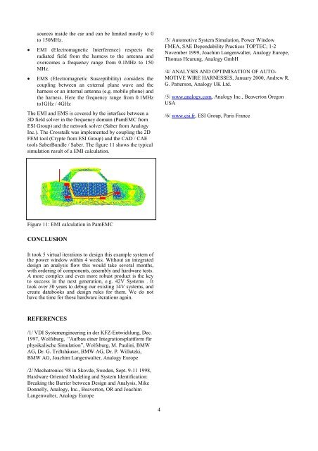
The EMI and EMS is covered by the interface between a<br />
3D field solver in the frequency domain (PamEMC <strong>from</strong><br />
ESI Group) and the network solver (Saber <strong>from</strong> Analogy<br />
Inc.). The Crosstalk was implemented by coupling the 2D<br />
FEM <strong>to</strong>ol (Crypte <strong>from</strong> ESI Group) and the CAD / CAE<br />
<strong>to</strong>ols SaberBundle / Saber. The figure 11 shows the typical<br />
simulation result of a EMI calculation.<br />
/3/ Au<strong>to</strong>motive System Simulation, Power Window<br />
FMEA, SAE Dependability Practices TOPTEC; 1-2<br />
November 1999, Joachim Langenwalter, Analogy Europe,<br />
Thomas Heurung, Analogy GmbH<br />
/4/ ANALYSIS AND OPTIMISATION OF AUTO-<br />
MOTIVE WIRE HARNESSES, January 2000, Andrew R.<br />
G. Patterson, Analogy UK Ltd.<br />
/5/ www.analogy.com, Analogy Inc., Beaver<strong>to</strong>n Oregon<br />
USA<br />
/6/ www.esi.fr, ESI Group, Paris France<br />
Figure 11: EMI calculation in PamEMC<br />
CONCLUSION<br />
It <strong>to</strong>ok 5 virtual iterations <strong>to</strong> design this example system of<br />
the power window within 4 weeks. Without an integrated<br />
design an analysis flow this would take several months,<br />
with ordering of components, assembly and hardware tests.<br />
A more complex and even more robust product is the key<br />
<strong>to</strong> success in the next generation, e.g. 42V Systems . It<br />
<strong>to</strong>ok over 30 years <strong>to</strong> debug our existing 14V systems, and<br />
create databooks and design rules for them. We do not<br />
have the time for those hardware iterations again.<br />
REFERENCES<br />
/1/ VDI Systemengineering in der KFZ-Entwicklung, Dec.<br />
1997, Wolfsburg, “Aufbau einer Integrationsplattform für<br />
physikalische Simulation”, Wolfsburg, M. Paulini, BMW<br />
AG, Dr. G. Triftshäuser, BMW AG, Dr. P. Willutzki,<br />
BMW AG, Joachim Langenwalter, Analogy Europe<br />
/2/ Mechatronics '98 in Skovde, Sweden, Sept. 9-11 1998,<br />
Hardware Oriented Modeling and System Identification:<br />
Breaking the Barrier between <strong>Design</strong> and Analysis, Mike<br />
Donnelly, Analogy, Inc., Beaver<strong>to</strong>n, OR and Joachim<br />
Langenwalter, Analogy Europe<br />
4