All-Wheel Drive / Four-Wheel Drive Systems and Strategies
All-Wheel Drive / Four-Wheel Drive Systems and Strategies
All-Wheel Drive / Four-Wheel Drive Systems and Strategies

You also want an ePaper? Increase the reach of your titles
YUMPU automatically turns print PDFs into web optimized ePapers that Google loves.
Seoul 2000 FISITA World Automotive Congress<br />
June 12-15, 2000, Seoul, Korea<br />
F2000A014<br />
<strong>All</strong>-<strong>Wheel</strong> <strong>Drive</strong> / <strong>Four</strong>-<strong>Wheel</strong> <strong>Drive</strong> <strong>Systems</strong> <strong>and</strong> <strong>Strategies</strong><br />
Sankar Mohan<br />
New Venture Gear, Inc. Troy,MI 48083 USA<br />
Modern <strong>Four</strong>-<strong>Wheel</strong> <strong>Drive</strong> (4WD) systems have become very sophisticated <strong>and</strong> infused with electronic control technology.<br />
These 4WD vehicles offer the appeal of an active lifestyle made possible by the assurance of a safe <strong>and</strong> secure vehicle, on<strong>and</strong><br />
off-road, along with the imp roved hauling <strong>and</strong> towing capabilities for people <strong>and</strong> equipment. The emphasis has been<br />
shifting from mere traction enhancement to on-road safety <strong>and</strong> h<strong>and</strong>ling improvement. There has also been a successful<br />
move to incorporate the above benefits in smaller, more fuel-efficient Front-<strong>Wheel</strong>-<strong>Drive</strong> (FWD) based vehicles generally<br />
called <strong>All</strong>-<strong>Wheel</strong> <strong>Drive</strong> (AWD) systems. This paper attempts to explain the control tactics, strategies <strong>and</strong> the philosophies<br />
behind various traction control systems.<br />
Keywords: <strong>Four</strong>-<strong>Wheel</strong>-<strong>Drive</strong>, <strong>All</strong>-<strong>Wheel</strong>-<strong>Drive</strong>, Traction control<br />
INTRODUCTION<br />
<strong>Four</strong>-<strong>Wheel</strong> <strong>Drive</strong> (4WD) systems have come a long<br />
way since the 1940s. From simple mechanical devices<br />
applied in military utility vehicles, they have evolved into<br />
the sophisticated systems infused with control technology<br />
that are available in modern, high speed, on-road vehicles.<br />
The improved mobility attained in difficult terrain by<br />
providing traction on all four tire patches was the major<br />
incentive to incorporate 4WD systems in drive trains. The<br />
early systems were cumbersome to engage into 4WD <strong>and</strong><br />
required driving skills beyond the capability of the average<br />
driver. The popularity of 4WD vehicles has soared<br />
because of the appeal of an active life style made possible<br />
by the assurance of a safe <strong>and</strong> secure vehicle, on- <strong>and</strong> offroad,<br />
along with the improved hauling <strong>and</strong> towing<br />
capabilities for people <strong>and</strong> equipment. Only lately have the<br />
4WD systems themselves become more user friendly.<br />
Since most people use the 4WD vehicles as on-road<br />
transportation, the emphasis has been shifting from mere<br />
traction enhancement to on-road safety <strong>and</strong> h<strong>and</strong>ling<br />
improvement. At the same time, there has been a<br />
successful move to incorporate the above benefits in<br />
smaller, more fuel efficient front-wheel-drive (FWD) based<br />
vehicles. These drive line architectures are generally called<br />
<strong>All</strong>-<strong>Wheel</strong> <strong>Drive</strong> (AWD) systems. This paper attempts to<br />
explain the control tactics <strong>and</strong> strategies <strong>and</strong> the<br />
philosophies behind various traction control systems.<br />
Towards this end, the paper also recounts for ready<br />
reference, the basic vehicle dynamics principles involved<br />
in the description of a vehicle's performance.<br />
BASIC DEFINITIONS<br />
4WD/AWD systems were developed in many different<br />
geographic markets <strong>and</strong> across different vehicle platforms,<br />
<strong>and</strong> so there is no universally accepted set of terminology<br />
to describe the various functions <strong>and</strong> architectures. In this<br />
<strong>and</strong> the following sections we will describe the generally<br />
accepted nomenclature along with some of the regional<br />
variations.<br />
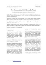
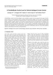
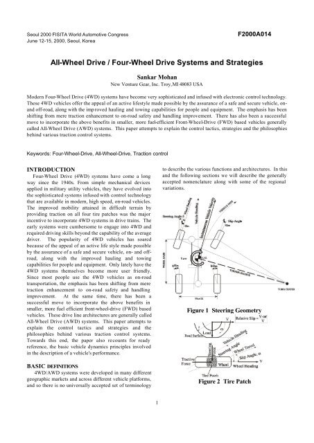
Yaw<br />
Figure 1 Steering Geometry<br />
Figure 2 Tire Patch<br />
1
The Ackerman steering geometry of a typical front<br />
wheel steered vehicle is shown in the Figure 1. As seen<br />
from the drawing, during a turn, the outer wheels must<br />
travel a longer path <strong>and</strong> so must rotate faster than the inner<br />
wheels. Similarly, the front axle must turn faster than the<br />
rear axle. If the driveline does not permit these differences<br />
in speeds, there could be undesirable driveline wind-up,<br />
especially on dry pavements where the relatively high<br />
surface friction prevents the tires from slipping easily. This<br />
could lead to poor fuel economy, undesirable tire<br />
scrubbing (‘crow-hop’) <strong>and</strong> damage to the driveline even<br />
during moderate maneuvers.<br />
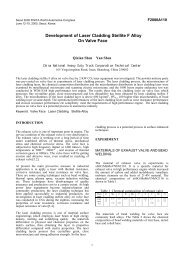
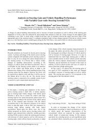
DRIVELINE ARCHITECTURES<br />
Typical 4WD/AWD drivelines are shown in Figures 3<br />
<strong>and</strong> 4. The engine rotation is modified by the transmission<br />
<strong>and</strong> distributed to the wheels by the transfer case through<br />
the propeller or drive shafts <strong>and</strong> the axles. The key<br />
characteristics of the various elements relevant to traction<br />
control will be summarized here.<br />
Engine<br />
Transaxle<br />
Engine<br />
Axle Shaft<br />
Axle<br />
Axle Shaft<br />
Axle Shaft<br />
Center Diff<br />
Power Take-off<br />
Axle Diff<br />
Axle Shaft<br />
Propshaft<br />
Coupling<br />
Axle Diff<br />
Figure 3 AWD Vehicle<br />
Center Diff<br />
Transmission<br />
Propshaft<br />
Axle Diff<br />
Coupling<br />
Transfer Case<br />
Axle Diff<br />
Propshaft<br />
Figure 4 4WD Vehicle<br />
Axle Shaft<br />
Axle<br />
Axle Shaft<br />
Axle Shaft<br />
Axle<br />
Axle Shaft<br />
THE ENGINE - Modern vehicles have engines that are<br />
typically fuel injected <strong>and</strong> controlled by an electronic<br />
control unit. Ignition spark control allows the engine<br />
power to be controlled in small ranges, but with quicker<br />
response times. Direct fuel control affords a wider range of<br />
power regulation but with a somewhat slower response<br />
time.<br />
THE TRANSMISSION - In manual transmissions, as the<br />
name implies, the control is left up to the driver. Automatic<br />
transmissions, especially the electronically controlled ones<br />
can be easily integrated into traction control systems to<br />
control the torque to the wheels.<br />
THE TRANSFER CASE – This may also be called Transfer<br />
Gearbox, Power Take-off Unit, PTU or PTO. This is an<br />
additional gearbox used to get the 4WD architecture. In<br />
Rear <strong>Wheel</strong> <strong>Drive</strong> (RWD) based vehicles, the Transfer<br />
Case distributes the torque to the two axles via the<br />
propeller shafts. In Front <strong>Wheel</strong> <strong>Drive</strong> (FWD) based<br />
vehicles, the Power Take Off Unit allows the drive shaft to<br />
the rear axle to be connected to the transmission. The ratio<br />
of the front axle torque (F%) to the rear axle torque (R%) is<br />
called the torque split ratio (F:R) of the transfer case. Some<br />
transfer cases have an added ‘low range’ to provide extra<br />
gear reduction for extreme torque dem<strong>and</strong>s at lower<br />
speeds. Typical transfer cases are designed to have<br />
multiple modes of operation. Depending on the<br />
implementation, the selection of the operating mode could<br />
be manual or electric <strong>and</strong> the switching times <strong>and</strong> the<br />
preconditions for switching might vary. The primary<br />
modes are described below.<br />
Two <strong>Wheel</strong> <strong>Drive</strong> (2WD) Mode - In this mode only<br />
one axle (typically the rear axle) is driven. The drive to<br />
the other axle is disconnected. The operating torque<br />
split ratio is 0:100.<br />
<strong>Four</strong> <strong>Wheel</strong> <strong>Drive</strong> (4WD) Mode - Here, depending on<br />
the nature of torque transfer to the axles, we can<br />
define three sub-modes.<br />
Part-time Mode - The front <strong>and</strong> rear axle drives are<br />
rigidly coupled in the transfer case. Since the<br />
driveline does not permit any speed<br />
differentiation between the axles <strong>and</strong> would cause<br />
driveline wind-up, this mode is recommended only<br />
for ‘part-time’ use in off-road or loose surface<br />
conditions where driveline wind-up is unlikely.<br />
Depending on the road condition <strong>and</strong> the weight<br />
over the axles, up to full torque could go to either<br />
axle.<br />
Full-time Mode - Both axles are driven at all times,<br />
but an inter-axle differential permits the axles to<br />
turn at different speeds as needed. This allows<br />
the vehicle to be driven ‘full-time’ in this mode,<br />
irrespective of the nature of the road surface,<br />
without fear of driveline wind-up. With st<strong>and</strong>ard<br />
bevel gear differentials the torque split is 50:50.<br />
Planetary differentials can provide asymmetric<br />
torque splits as needed. A system that operates<br />
permanently in the full-time mode is sometimes<br />
called the ‘<strong>All</strong>-the-Time 4WD’, '<strong>All</strong>-<strong>Wheel</strong>-<strong>Drive</strong>'<br />
or ‘AWD’. If the inter-axle differential is locked<br />
out, then the mode reverts to a ‘part-time mode’.<br />
On-Dem<strong>and</strong> Mode - In this mode, the transfer<br />
case operates primarily in the 2WD mode. Torque<br />
is transferred to the secondary axle ‘on-dem<strong>and</strong>’<br />
or as needed, by modulating the transfer clutch<br />
from ‘open’ to a rigidly coupled state, while<br />
avoiding any driveline wind-up. The torque<br />
modulation may be achieved by active<br />
electronic/hydraulic control systems, or by<br />
passive devices, based on wheel slip or wheel<br />
2
torque, as described in the section on traction<br />
control systems.<br />
In addition to these basic modes, there could be<br />
implementations that combine these modes. For<br />
example, the system could have a clutch across the<br />
center differential, capable of modulating the front axle<br />
torque from a Full-time mode with the 30:70 torque<br />
split of the center differential rather than from the 0:100<br />
torque split of the 2WD mode.<br />
AXLE – The axle consists of the structural housing,<br />
differential <strong>and</strong> the drive shafts to each wheel. A propeller<br />
shaft from the Transfer Case drives the input gear of the<br />
axle differential. The axles allow the wheels to rotate at<br />
different speeds during turns by distributing the torque<br />
DIFFERENTIAL - The center differential is located in the<br />
transfer case or the PTU, between the two outputs. The<br />
axle differential is in the axle, between the two axle drive<br />
shafts.<br />
The differential distributes the input rotation to the two<br />
outputs that are allowed to turn at different speeds, <strong>and</strong><br />
can be thought of as a torque balancing device between<br />
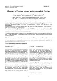
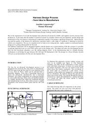
the two driven elements. A schematic drawing of a generic<br />
(bevel gear or planetary) differential is shown in Figure 5.<br />
The 'open' differential does not have the optional torque<br />
bias device ‘x’ shown. In ‘true’ differentials, if one of the<br />
outputs slows down, there is a corresponding speed up of<br />
the other output. In other words, the input speed always<br />
Figure 5 4WD Modes<br />
through the axle differential. The rigid axle unit, which<br />
integrates all above elements, is typically connected to the<br />
chassis via the suspension elements. The independent<br />
axle unit, housing just the differential is rigidly attached to<br />
the chassis <strong>and</strong> half shafts <strong>and</strong> Constant Velocity (CV)<br />
joints connect the outputs from the differential to the<br />
wheels that are connected to the chassis via the<br />
suspension elements. The axle drive shafts could be<br />
permanently connected to the wheels (live axles) or could<br />
permit disconnecting the wheel(s) (disconnect axles) to<br />
prevent drag losses when the axle is not being driven. The<br />
disconnect device could be a manual or a power-actuated<br />
mechanism.<br />
remains the average of the two output speeds. This<br />
kinematic relationship also constrains the input torque in<br />
such differentials to be limited by the smaller of the two<br />
output torques. The biasing device ‘x’ across the<br />
differential partially removes this limitation <strong>and</strong> allows the<br />
differential to transmit more torque to the outputs than an<br />
open differential. This biasing may be dependent on the<br />
speed difference between the two outputs (speed sensitive<br />
limited slip), the torque at the outputs (torque sensitive<br />
limited slip) or some external criterion as determined by a<br />
control logic (active, intelligent limited slip). In some<br />
quasi-differential devices, the differential action is<br />
achieved simply by permitting one output to overrun the<br />
other.<br />
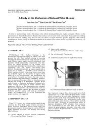
BASIC VEHICLE DYNAMICS<br />
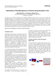
The primary motive forces on the vehicle are applied at<br />
the tire patches in contact with the road surface. The total<br />
maximum friction force at the tire patch is limited by the<br />
contact load <strong>and</strong> the coefficient of friction (µ) with the<br />
Figure 6<br />
3
oad. The longitudinal component of this force is the<br />
maximum available tractive/braking force <strong>and</strong> the<br />
transverse or lateral component is the maximum available<br />
steering force. The actual traction <strong>and</strong> steering forces will<br />
also depend on the wheel relative slip, the wheel slip angle<br />
<strong>and</strong> the road condition as shown in Figures 7 <strong>and</strong> 8. It must<br />
be noted that ‘on-road’ surfaces generate peak traction at<br />
relatively low slip where as ‘off-road’ surfaces like gravel<br />
generate maximum traction at much higher slip.<br />
high <strong>and</strong> tires roll without much side-slip. But due to<br />
imperfections in the steering geometry <strong>and</strong> driveline<br />
couplings there could be some tire scuffing. This effect<br />
would become pronounced if the drivetrain does not permit<br />
speed differentiation either within or between the axles.<br />
The driveline <strong>and</strong> suspension wind-up <strong>and</strong> subsequent<br />
release of this energy, through tire slippage on the road<br />
surface, results in an uneven combination of linear <strong>and</strong><br />
yaw motion. This movement known as 'crow-hop' could be<br />
annoying in the least or cause driveline failure at the worst.<br />
The effect also feeds back to the driver as a stiffening of<br />
the steering effort.<br />
Figure 7 Friction Circle<br />
Referring to Figure 8, if the applied wheel drive torque is<br />
increased, the wheel slip at the tire patch increases to<br />
generate the traction. The initial slip mechanism is due to<br />
elastic deformation of the tire walls. The slip gradually<br />
increases as the treads start sliding on the road. Once the<br />
applied torque exceeds the maximum traction available at<br />
the tire patch, the wheel will get into a run-away slip<br />
condition as may be seen in Figure 8. Even if only one of<br />
the wheels slips, the traction at an axle is reduced due to its<br />
influence on the other wheel through the open differential.<br />
In addition to the loss of traction, the available steering<br />
force also reduces at the slipping wheel <strong>and</strong> this affects<br />
directional stability of the vehicle. As discussed earlier,<br />
drivetrains, especially with open differentials will lose<br />
overall traction at an axle if either or both of the two wheels<br />
lose traction. This would happen if the road surface<br />
provides a low coefficient of friction (µ) with the tire. It<br />
could also happen if the load at the tire patch is reduced<br />
due to dynamic load transfer or due to suspension effects.<br />
During vehicle launch from low µ surfaces, tire spin up<br />
should be avoided to reduce the chances of getting stuck.<br />
On snow covered surfaces the problem occurs because the<br />
spinning tire tends to push away the top layer, compact<br />
the inner layer <strong>and</strong> polish it into an extremely low µ surface<br />
further reducing available traction. On s<strong>and</strong> or mud, the<br />
spinning action buries the wheel <strong>and</strong> increases the effort<br />
needed to get out.<br />
Tire spin up during launch, even with straightened<br />
wheels, would cause the vehicle to be susceptible to yaw<br />
disturbances <strong>and</strong> cause the rear end to swing around or<br />
‘fishtail’. With steering input, as during cornering, the<br />
vehicle behavior is very dependent on the speed. In low<br />
speed turning maneuvers, the steering angles are typically<br />
Figure 8 Traction vs Slip<br />
At higher cornering speeds, the lateral accelerations<br />
experienced by the vehicle become significant. Lateral<br />
steering forces are required at the wheels to push the<br />
vehicle into the desired path. This requires all the wheels<br />
to operate under some side slip condition. As described in<br />
the sections on tire patch mechanics <strong>and</strong> vehicle dynamics,<br />
the load <strong>and</strong> the coefficient of friction limit the total friction<br />
force at the tire. So acceleration or braking during<br />
cornering could reduce the available lateral steering forces<br />
at the tires. If this happens at the front wheels, the vehicle<br />
would want to go straight, turn less than intended <strong>and</strong><br />
understeer. If the rear wheels have insufficient steering<br />
force, they slide outward <strong>and</strong> the vehicle would turn into<br />
the corner <strong>and</strong> oversteer. Any other phenomenon like<br />
dynamic load transfer or camber change due to the<br />
suspension will change the magnitude <strong>and</strong> or direction of<br />
the steering forces at the tires <strong>and</strong> will influence the<br />
cornering ability.<br />
Braking also could affect the vehicle’s h<strong>and</strong>ling ability.<br />
Premature lock up of the front wheel during braking will<br />
cause loss of steering ability. If lock up occurs at the rear<br />
wheels, the stability of the vehicle itself is compromised<br />
<strong>and</strong> the vehicle might end up spinning about its vertical<br />
axis due to amplification of any yaw disturbance.<br />
NEED FOR TRACTION CONTROL<br />
The ideal drivetrain allows the driver to propel the<br />
vehicle in the intended direction <strong>and</strong> speed in a manner<br />
that promotes the ease <strong>and</strong> ability to maintain control. This<br />
requires not only a capacity to respond to the driver's<br />
inputs in a predictable manner but also the ability to feed<br />
4
ack useful information to the driver. In the final analysis,<br />
it is the performance of the driver/vehicle system (loosely<br />
called the 'h<strong>and</strong>ling') that is important in assessing the<br />
success or limitation of a particular traction control<br />
implementation. Although the primary contributor is the<br />
drivetrain, the steering, suspension <strong>and</strong> braking systems<br />
also influence the vehicle's h<strong>and</strong>ling performance.<br />
Ultimately, the laws of physics dictate the static <strong>and</strong><br />
dynamic limits of performance of the vehicle under all road,<br />
load <strong>and</strong> speed conditions.<br />
The typical driver uses the vehicle, most of the time,<br />
well below its dynamic limit. It is desirable to enhance the<br />
tractive/braking ability <strong>and</strong> the directional stability of the<br />
vehicle, thus allowing the driver to exp<strong>and</strong> the envelope of<br />
performance without reducing safety <strong>and</strong> the sense of<br />
maximum available tire force may be controlled by<br />
adjusting the tire slip at the tire patch (Figures 2 <strong>and</strong> 8).<br />
Most control systems leave the steering to the driver <strong>and</strong><br />
attempt to control the tire slip to achieve both traction <strong>and</strong><br />
stability improvement. Taking a closer look at Figure 8, we<br />
realize that the operating point along the slip curve is<br />
determined by the matching of the maximum available<br />
resisting force at the tire patch <strong>and</strong> the applied torque at<br />
the wheel. Under quasi steady-state operation, within the<br />
peak limit, if the applied torque is altered, the tire slip<br />
changes till a matching tire force can be generated.<br />
Beyond the peak limit, of course, there is runaway slip of<br />
the tire. This opens up three avenues for control.<br />
1. Reapportion the applied torque among the wheels.<br />
Control Devices<br />
Reapportion<br />
Torque<br />
Limited Slip<br />
Clutches<br />
Tire Patch Torque Control<br />
Control amount of Torque<br />
Reduce Torque<br />
Reduce applied Absorb excess<br />
Torque<br />
Torque<br />
Power Management Selective Brake<br />
Application<br />
Figure 9: Tire Patch Torque Control<br />
Increase Torque<br />
Active Torque<br />
Control<br />
control. This in essence is the purpose of the traction<br />
control system. To restate this in simpler terms, the traction<br />
control system should improve the mobility at low speeds<br />
<strong>and</strong> in difficult terrain by improving the tractive<br />
performance, <strong>and</strong> improve the safety <strong>and</strong> h<strong>and</strong>ling at<br />
higher speeds by improving the directional stability. To<br />
the average driver, this would translate to better<br />
performance <strong>and</strong> safer h<strong>and</strong>ling even under adverse<br />
driving conditions. The ways in which traction <strong>and</strong><br />
directional stability might be compromised was described<br />
in the previous section on vehicle dynamics.<br />
TACTICS FOR TRACTION CONTROL<br />
Before we discuss the strategies of control, let us look<br />
at the tactics available for control. Since the only active<br />
external forces on the vehicle comes from the tire patches,<br />
our sole option is to control or influence the tire patch<br />
dynamics. As seen earlier, the effective maximum friction<br />
force obtainable at each tire patch is governed by the<br />
normal force <strong>and</strong> the available coefficient of friction, both<br />
of which are difficult to influence. Many independent<br />
suspension systems maintain tire/ground contact by<br />
allowing a larger jounce range for the wheels. Some<br />
advanced active suspension control systems do adjust the<br />
effective dynamic load at the tire patch. But mostly we<br />
have control over only two of the key elements. First, the<br />
apportioning of the tire force between the tractive <strong>and</strong><br />
steering forces may be controlled by manipulating the tire<br />
slip angle via the steering (Figures 2 <strong>and</strong> 7). Second, the<br />
This is the approach taken by all limited slip<br />
differentials <strong>and</strong> on-dem<strong>and</strong> torque transfer clutches.<br />
2. Control the amount of applied torque in the drive train.<br />
This is the approach taken by engine <strong>and</strong> transmission<br />
control integration with traction control (power<br />
management).<br />
3. Absorb the excess torque at the tire patch. This is the<br />
approach taken by the brake based traction <strong>and</strong><br />
stability control systems (eg. ESP- Electronic Stability<br />
Program).<br />
Limited Slip Differentials And On-Dem<strong>and</strong> Torque Transfer<br />
Clutches. These devices may be passive devices with<br />
operating characteristics dependent on some intrinsic<br />
physical phenomenon inherent to the device or active<br />
devices that use an external logic to control their<br />
characteristic. Passive units widely used are the slip<br />
sensitive mechanisms like the viscous or Gerodisc<br />
couplings as well as the torque sensitive devices like the<br />
Torsen or the Suretrac differentials. <strong>All</strong> active clutches use<br />
a control system that utilizes other vehicle operating<br />
parameters to decide when, how long <strong>and</strong> how strongly to<br />
activate the clutch. The extent of these control systems is<br />
defined by technical considerations like the level of<br />
complexity <strong>and</strong> adaptations required as well as by cost<br />
considerations. Obviously, the active clutches lend<br />
themselves to integration with other vehicle subsystems<br />
for a more effective overall traction <strong>and</strong> stability control<br />
system.<br />
5
Power Management. As mentioned earlier, most modern<br />
engines <strong>and</strong> automatic transmissions are electronically<br />
controlled <strong>and</strong> may easily be adapted <strong>and</strong> integrated into<br />
the traction <strong>and</strong> stability control system.<br />
Brake Based Traction And Stability Control <strong>Systems</strong>.<br />
Lately a number of systems have been introduced in the<br />
market based on the principle of selectively applying the<br />
individual wheel brakes to achieve slip reduction, descent<br />
control or yaw control.<br />
Yaw Control. Yaw motion is the rotation of the vehicle<br />
about the vertical axis through its center of mass <strong>and</strong> the<br />
'yaw-rate' is the speed of that rotation. The effect of the<br />
external applied forces about the axis through the center of<br />
mass is the ‘yaw-moment’. Vehicle motion along the road<br />
surface may be thought of as a combination of linear <strong>and</strong><br />
inner rear wheel<br />
is braked<br />
Understeer<br />
Intended Path<br />
outer front wheel<br />
is braked<br />
Oversteer<br />
Figure 10 Yaw Control<br />
yaw motion. Ideally, during straight line launch, there is no<br />
yaw motion. Any yaw indicates an imbalance or left to<br />
right assymetry in the tractive forces at the wheels. During<br />
cornering, the vehicle yaws at a rate proportional to the<br />
linear speed (V) <strong>and</strong> inversely proportional to the turning<br />
radius (r). Under rolling or no-slip conditions, the steering<br />
angle, wheelbase <strong>and</strong> the track of the vehicle determine its<br />
turning radius. The vehicle also experiences a lateral<br />
acceleration corresponding to (V 2 /r). By measuring the<br />
individual wheel speeds, steering angle, throttle position,<br />
brake pressure <strong>and</strong> lateral acceleration, the control system<br />
can determine the driver’s intent <strong>and</strong> the desired yaw-rate.<br />
To judge the vehicle’s response to the driver input<br />
requires the additional measurement of the actual yaw-rate<br />
using a yaw-rate sensor. Comparing the desired to the<br />
actual yaw-rate allows the controller to apply corrective<br />
yaw-moment.<br />
The brake based yaw-rate control is an extension of the<br />
Antilock Brake System (ABS) <strong>and</strong> shares many of its<br />
components. The control program selectively applies the<br />
brakes of the four wheels to create a correcting moment to<br />
offset the yaw-rate. Typically, as illustrated in Figure 10,<br />
oversteer may be countered by the application of the outer,<br />
front wheel brake <strong>and</strong> understeer may be countered by<br />
application of the inner, rear wheel brake. Although quick<br />
acting, effective <strong>and</strong> acceptable, this method is essentially<br />
a braking maneuver <strong>and</strong> so reduces the speed performance<br />
slightly.<br />
Recently some carmakers have introduced yaw control<br />
based on intentionally varying the torque split between the<br />
wheels to generate the desired yaw-moment. The additive<br />
tractive effort might give them some advantage over the<br />
subtractive nature of the brake-based systems. It is too<br />
early to say whether these systems offer significant<br />
performance improvements consistent with the added<br />
mechanical complexity, weight <strong>and</strong> cost.<br />
CONTROL SYSTEMS STRATEGIES<br />
There is no universal strategy that will satisfy all types<br />
of drivers under all kinds of driving conditions. The<br />
particular strategy employed depends on the limitations of<br />
the vehicle, the philosophy behind the calibration <strong>and</strong> of<br />
course cost. Advances in electronics <strong>and</strong> miniaturization<br />
<strong>and</strong> micromachined sensors have allowed the development<br />
of sophisticated systems that are fast enough to do the<br />
real time computations necessary <strong>and</strong> yet are small enough<br />
to be packaged <strong>and</strong> affordable. As the cost of providing<br />
advanced technology comes down, it becomes feasible to<br />
apply it more universally. It also becomes increasingly<br />
desirable to coordinate <strong>and</strong> integrate the control of the<br />
various vehicle subsystems like engine, transmission,<br />
steering, brakes <strong>and</strong> suspension <strong>and</strong> benefit from their<br />
interactions rather than allow them to operate<br />
independently.<br />
The philosophy that defines the calibration or tuning of<br />
the control system is dependent on the relative emphasis<br />
placed on making the vehicle safer for even the unskilled<br />
driver <strong>and</strong> the desire to enlarge the operating envelope of<br />
the vehicle under adverse driving conditions. The control<br />
system should minimize abrupt changes in the behavior of<br />
the vehicle within its extended operating envelope. It<br />
should also be predictable <strong>and</strong> provide sufficient feedback<br />
<strong>and</strong> warning to the driver when approaching the vehicle’s<br />
critical dynamic limits.<br />
Some carmakers, with safety in mind, have chosen to<br />
intervene aggressively <strong>and</strong> early on to prevent the driver<br />
from pushing the vehicle beyond ‘safe’ limits. This<br />
approach necessarily involves power management <strong>and</strong><br />
takes away absolute throttle control from the driver close<br />
to these limits. Other manufacturers, with an eye on<br />
performance, have allowed the driver some leeway in<br />
applying minor corrections using steering, throttle <strong>and</strong><br />
brake <strong>and</strong> enforce throttle <strong>and</strong> brake control only to<br />
prevent the vehicle from losing total control <strong>and</strong> becoming<br />
unsafe.<br />
Many of the current systems allow the driver to switch<br />
off the traction control setting. It is quite possible that in<br />
the future, manufacturers can allow the driver the option of<br />
a graduated calibration setting somewhat similar to the<br />
6
‘soft’ <strong>and</strong> ‘sporty’ setting seen in some electronically<br />
controlled automatic transmissions.<br />
SUMMARY<br />
Even though there will always be a market segment that<br />
utilizes the simp le, st<strong>and</strong>-alone transfer cases <strong>and</strong> PTUs,<br />
the advanced traction control systems of the future will<br />
benefit from integration with the other subsystems like<br />
engine, transmission, brakes <strong>and</strong> suspension. The thrust<br />
will be to enhance the traction, stability <strong>and</strong> safety of the<br />
vehicles under adverse, off-road as well as high speed onroad<br />
driving conditions. The specific control strategy<br />
employed should take into consideration the nature of the<br />
vehicle, the anticipated driving pattern, the expectations of<br />
the driver in that market segment <strong>and</strong> the relative emphasis<br />
placed on safety <strong>and</strong> performance. Technological<br />
advancements will ensure that future traction control<br />
systems will be more transparent, safer, lighter, more<br />
efficient <strong>and</strong> more complex in a ‘systems’ sense.<br />
ACKNOWLEDGEMENTS<br />
The author wishes to thank the numerous professional<br />
colleagues who have enriched the author’s knowledge <strong>and</strong><br />
experience of the drivetrain technology. The author is<br />
especially grateful to Dan Miller for his assistance in<br />
preparing this paper.<br />
[3] Ikushima, Yoshihiro et al, A Study on the Effects of the<br />
Active Yaw Moment Control, (SAE 950303), 1995<br />
[4] Matsuo, Yoshiaki et al, Intelligent <strong>Four</strong>-<strong>Wheel</strong>-<strong>Drive</strong><br />
System, (SAE 930670), 1993.<br />
[5] Mohan, Sankar K. et al, A Survey of 4WD Traction<br />
Control <strong>Systems</strong> <strong>and</strong> <strong>Strategies</strong>, (SAE 952644), 1995<br />
[6] Mohan, Sankar K., AWD/4WD <strong>Systems</strong> <strong>and</strong> <strong>Strategies</strong>,<br />
Advanced Transmission Design & Performance Vol.8,<br />
(GPC'99), 1999.<br />
[7] Ohba, Mitsuru et al, Development of a New<br />
Electronically Controlled 4WD System: Toyota<br />
Active Torque Control 4WD, (SAE 1999-01-0744),<br />
1999<br />
[8] Shinohara, Minoru et al, Nissan Electronically<br />
Controlled <strong>Four</strong> Speed Automatic Transmission,<br />
(SAE 890530), 1989.<br />
[9] Yamaguchi, Jack, Toyota Vehicle Stability Control<br />
System., Automotive Engineering, Aug. 1995.<br />
[10] Yamomoto, M., Active Control Strategy for Improved<br />
H<strong>and</strong>ling <strong>and</strong> Safety, (SAE 911902), 1991.<br />
[11] Zomotor, A. et al, Mercedes - Benz 4MATIC, An<br />
Electronically Controlled <strong>Four</strong> <strong>Wheel</strong> <strong>Drive</strong> System<br />
for Improved Active Safety., (SAE 861371), 1986.<br />
------------------<br />
REFERENCES<br />
[1] Gillespie, Thomas D., Fundamentals of Vehicle<br />
Dynamics, SAE Publications Book, 1992.<br />
[2] Hoeck, Michael., The Influence of Various 4WD<br />
<strong>Drive</strong>line Configurations on H<strong>and</strong>ling <strong>and</strong> Traction<br />
on Low Friction Surfaces, (SAE 1999-01-0743), 1999<br />
7