Development of Laser Cladding Stellite F Alloy On Valve Face
Development of Laser Cladding Stellite F Alloy On Valve Face
Development of Laser Cladding Stellite F Alloy On Valve Face

Create successful ePaper yourself
Turn your PDF publications into a flip-book with our unique Google optimized e-Paper software.
Seoul 2000 FISITA World Automotive CongressJune 12-15, 2000, Seoul, KoreaF2000A110<strong>Development</strong> <strong>of</strong> <strong>Laser</strong> <strong>Cladding</strong> <strong>Stellite</strong> F <strong>Alloy</strong><strong>On</strong> <strong>Valve</strong> <strong>Face</strong>Qixian ShenYan Shen165 Yingxiongshan Road, Jinan, Shandong, China 250002The laser cladding stellite F alloy on valve face by 2 KW CO 2 laser equipment was investigated. The powder mixture pastewas pre-coated on valve face in experiments <strong>of</strong> laser cladding process. The laser cladding process, the microstructure <strong>of</strong>laser cladding layer, the chemical composition distribution and the microhardness distribution in laser cladding layer wereexamined by metallurgical microscope and scanning electric microscope, and the 1000 hours engine endurance test wasconducted in WD615.68 high performance test engine. The results show that the cladding layer on valve face whichpossesses fine crystalline grain, close microstructure and low dilutability has been obtained by laser cladding stellite Falloy. The microhardness <strong>of</strong> the laser cladded layer is above 600 kg/mm 2 , HV 0.2 100 higher than microhardness <strong>of</strong> beadwelding layer at same depth. The operational performances <strong>of</strong> the laser cladding layer such as wear resistance performanceand erosion resistance performance etc completely meet the requirements <strong>of</strong> high performance engine. The laser claddingprocess on valve face is a potential process in automotive industry.Keyword: <strong>Valve</strong> <strong>Face</strong> <strong>Laser</strong> <strong>Cladding</strong> <strong>Stellite</strong> <strong>Alloy</strong>INTRODUCTIONThe exhaust valve is one <strong>of</strong> important parts in engine. Theservice condition <strong>of</strong> the exhaust valve is very deteriorative.The exhaust valve is working over a long period <strong>of</strong> timeunder combined effects <strong>of</strong> thermal stress, mechanicalstress and chemical corrosive stress. The valve face issubjected to high frequency impact at 1400 times/s., hightemperature at 500C~800C, and erosion <strong>of</strong> thermalcorrosion gases at 600m/s. The valve faces will be gettingerosion and abrasive wear, even resulted in cracking <strong>of</strong>exhaust valve[1.2].At present the main preventive measure in industrialapplication is to apply a layer with thermal resistance,corrosive resistance and wear resistance on valve face.There are some coating techniques such as bead welding,thermal spary, plasma spray, vacuum induction weldingetc. These techniques have disadvantages <strong>of</strong> qualityassurance and production cost to a certain extent. As highpower laser equipments become industrialization andcommodity production, the laser cladding technique hasbeen applied successfully to industrial production. Aninvestigation in laser cladding stellite alloy on valve facewas conducted in USA during the eighties, increasing theproperties <strong>of</strong> wear resistance, corrosion resistance andimpact resistance <strong>of</strong> valve[3.4].The laser cladding process is one <strong>of</strong> material surfaceengineerings which employes laser beam <strong>of</strong> high energydensity, melting and solidifying quikly the materialsdifferential in physical and chemical properties on thematrix surface, then obtaining the layer in propertiesdifferential compared with matrix properties. The lasercladding layers possess fine crystalline grain, closemicrostructure and storng adhesion strength. So the lasercladding process is a potential process in surface enhancedtechniquesEXPERIMENTMATERIALS OF EXHAUST VALVE AND BEADWELDINGThe material <strong>of</strong> exhaust valve in experiments isx60CrMnMoVNbN2110. It is a specific material forexhaust valve in high performance engine which increasedthe amount <strong>of</strong> carbon and added molybdeum, vanadium,niobium elements on the basis <strong>of</strong> 21-4N material. Thechemical composition <strong>of</strong> x60CrMnMoVNbN2110 isshown in Table 1.ElememtsContents(%)Table 1 Chemical composition <strong>of</strong> exhaust valveCr Mo C Si Mn P S V Nb N20-220.75-1.250.57-0.650.25 9.5-11.50.0500.0250.75-1.00The materials <strong>of</strong> bead welding for valve face arecommonly hard alloys. The Table 2 shows the chemicalcomposition <strong>of</strong> bead welding materials <strong>of</strong> iron base, nickelbase and cobalt base.1-1.20.4-0.61
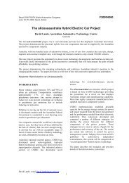
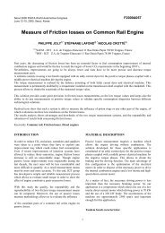
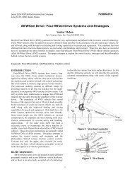
Table 2 Chemical composition <strong>of</strong> bead weldingmaterials(%) <strong>Stellite</strong> 6, stellite 12 and stellite F alloys are used as beadwelding materils for valve face in diesel engines. Amongthese bead welding materials the stellite F alloy iscommomly used. These materials include more alloyelement contents <strong>of</strong> such elements as nickel, chromium,cobalt etc in higher content which give greater hardnessand resistance to wear. The hardness at high temperaturefor exhause valve materials and bead welding materials areshown in Table 3.EXAMINATION METHODMetallographic structure <strong>of</strong> laser cladding layer on valvefave was eximined using MeF3 metallograph.Microhardness distribution was astimated by Micro-Duromat 4000E microhardness tester. The chemicalcomposition and the area distribution <strong>of</strong> iron elememt wasdetermined using PV9900 energy dispersive x-ray analyzerand WDX-2A wavelenth dispersive x-ray spectrometer.Further, 1000 hours durability engine test for the exhaustvalve with laser cladding stellite F alloy was conducted ina WD615.68 high-performance test engine.RESULTS AND DISCUSSIONMETALLOGRAPHIC STRUCTUREThe metallogphic structures <strong>of</strong> laser cladding layer andbead welding layer are shown in Fig.1 and Fig.2.Table 3 Hardness at high temperature for exhaust valvematerials and bead welding materials Fig.1 Metallogphic structure <strong>of</strong> LC layer 100 In experiments, stellite F alloy is selected as laser claddingmaterial, stellite 6 is selected as bead welding material forcompareson experiment.LASER CLADDING PROCESSA 2KW CO 2 laser beam welding apparatus was used forlaser cladding process. The method <strong>of</strong> pre-laid podwermixture paste over on the surface <strong>of</strong> valve face wasdetermined as pre-treatment method. The thickness <strong>of</strong> prelaiedpowder mixture paste over is about 2 mm. The laserpower is 2KW. The diameter <strong>of</strong> laser beam is 5 mm. Thescanning speed <strong>of</strong> laser beam is 2.8-7.2 mm/s. Nitrogengas was used during laser cladding process for prevention<strong>of</strong> oxidation and buring <strong>of</strong> cladding powder.Fig.2 Metallogphic structure <strong>of</strong> BW layer 100Fig.1 shows that the metallographic structure <strong>of</strong> lasercladding layer is a typical branched structure which iscomposed <strong>of</strong> fine, even rounded crystals and branchedcrystals diffirent in shape after laser cladding stellite Falloy. Three ranges can be divied in cross section <strong>of</strong> ametallographic sample in the vertical direction <strong>of</strong> surface<strong>of</strong> laser cladding layer: the melted range, the heat influence2
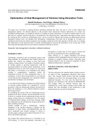
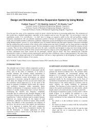
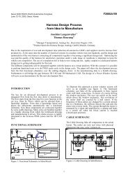
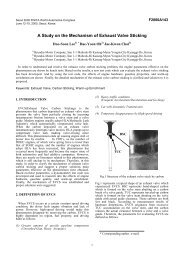
ange and the substrate. There is a obrious rapidly-coolinglayer near the substrate. The fine branched crystals locatein the surface layer. In the center part there are branchedcrystals unregular in the direction. The pre-laid powderlayer will be quick-melted partly or total as the powerdensity <strong>of</strong> laser is very high. Through contraling theparameters <strong>of</strong> laser the substrate can be melted hardly.During rapidly cooling <strong>of</strong> laser cladding layer the contents<strong>of</strong> alloy elements existed in matrix phase will be increased.These alloy elements distribute in the matrix phase r as theclose and complex eutectic carbides which appear in forms<strong>of</strong> network structure.In bead welding process large scale branched crystalspresent in the matrix phase r. Rapidly-cooling layer nearthe substrate has not be observed clearly. The contents <strong>of</strong>carbon, tungsten etc have be dicreased, then it promotedcoare-grain structure because the melted range near thesubstrate was enlarged in bead welding process. Accordingto the examination results the melted range <strong>of</strong> lasercladding layer is 0.38mm less than the melted range <strong>of</strong>bead welding layer. The process <strong>of</strong> rapidly melting andcooling in laser cladding reduces evidently the range <strong>of</strong>heat influence. In the range <strong>of</strong> heat influence <strong>of</strong> beadwelding the austenite and lamellar Cr 2 N structure willweaken the thermal strength and corrosion resistance <strong>of</strong>the steel[5].direction from the surface to the inner, the microhardness<strong>of</strong> layer distributes from high to low. In the trasition range<strong>of</strong> laser cladding layer the coare-needle martensite resultsin microhardness drop, a low tide occurred in themicrohardness curve. But the crypto-crystalline martensitein the range <strong>of</strong> phase change will intensify microhardness.The extent <strong>of</strong> oxidation and decarburization <strong>of</strong> the surfacein bead welding process is more serious than that in lasercladding process, increasing the content <strong>of</strong> hypo-eutecticbainite and reducing microhardness, the peak <strong>of</strong>microhardness curve is moved to subsurface layer. Themicrohardness droped markedly in comparison with lasercladding process. The microhardness <strong>of</strong> laser claddinglayer is about HV 0.2 100 higher than that <strong>of</strong> bead weldinglayer at same depth.COMPOSITION DISTRIBUTIONMICROHARDNESSEquidistance pointFig.4 Element distribution <strong>of</strong> LC layerDistance to the surface(mm)Fig. 3 Microhardness <strong>of</strong> LC and BW layersFig.3 shows the microhardness distribution <strong>of</strong> the lasercladding layer and the bead weding layer. From Fig.3 itcan be observed that the curve amplitude <strong>of</strong> microhardnessdistribution <strong>of</strong> the laser cladded layer is gentler and thehardened range is larger. However, the curve amplitude <strong>of</strong>microhardness distribution <strong>of</strong> the bead welded layer ismore fluctuant and the hardened range is smaller. Themicrohardness <strong>of</strong> the laser cladding layer is above 600kg/mm 2 .Because the density <strong>of</strong> laser power is very high,usually the density <strong>of</strong> laser power <strong>of</strong> KW class is 10 5 ~10 7w/cm 2 , and the time for finishing laser cladding process isonly in o.1~1 second, the structure <strong>of</strong> the laser claddinglayer should be fine and close at so high heating andcooling speed. And the higher microhardness <strong>of</strong> lasercladding layer should be obtained.As quick melting and solidifying promote fine grainstructure in surface layer, moreover the change <strong>of</strong> thestructure from the fine to the coarse distributed along theEquidistance pointFig.5 Element distribution <strong>of</strong> BW layerFig.4 and Fig.5 show the main element distributions in thelaser cladded layer and the bead welded layer by energydispersive analyzer <strong>of</strong> x-ray. From these compositiondistributions, it is clear that the dilutability in lasercladding layer is much lower than that in bead weldinglayer.3
The results <strong>of</strong> area scanning <strong>of</strong> Fe element reveal that theboundary between the laser cladding layer and thesubstrate is clearer and the effect <strong>of</strong> subsrate compositionson the laser cladding layer is very small (see Fig.6).However the bead welding layer was much affected by thesubstrate composition (see Fig.7).The results are consistentwith that obtained in energy x-ray dispersive analysis (seeFig.4 and Fig.5).Endurance timeEngine powerMaximum torqueMinimum fuel consumption1000 Hs.232.9-244.2 KM1245-1302 Nm.197.8 g/kw.hAfter the engine endurance test was finished, the testedexhaust valve were dissembled and examined. Theexamination results indicated that the wear resistance <strong>of</strong>the laser cladded exhaust valve is very well, the wearingvalue is 25%~62.5% as low as normal wearing value. Thefailure problems <strong>of</strong> erosion, peeling and cracking did notbe discovered in tested valve faces. It demostrates that thelaser cladded exhaust valves have good properties andexcellent performances in high power diesel engines andthe laser claddding process is successful in application <strong>of</strong>exhaust valve faces.CONCLUSIONFig.6 Area scanning <strong>of</strong> Fe <strong>of</strong> LC layer1. The cladding layer with fine crystalline grain and closemicrostructure has been obtained in valve face by lasercladding stellite F alloy2. The laser cladding process has the advantage <strong>of</strong> lowerdilutability in cladding layer, so it can decrease thethickness <strong>of</strong> cladding layer and cut down cladding materialexpenses.3..Higher microhardness and more reasonablemicrohardness distribution in cladded layer can beproduced by laser cladding process. The microhardness <strong>of</strong>the laser cladded layer is above 600 kg/mm 2 , HV 0.2 100higher than microhardness <strong>of</strong> bead welding layer at samedepth.Fig.7 Area scanning <strong>of</strong> Fe <strong>of</strong> BW layerBecause the density <strong>of</strong> laser power is higher and the time<strong>of</strong> laser action is shorter in laser cladding process,theenergy less in heating process is lower, the range <strong>of</strong> heateffect is smaller also, and then the molten capacity <strong>of</strong> thesubstrate and the action <strong>of</strong> dilution to cladding layerbecame smaller. From above-mentiened reasons thecompositions required for assured properties can beobtained in the thinner laser cladded layer and theexpensive cladding materials can be saved. The lasercladding process is a better process than the bead weldingfor enhancing the valve face.ENGINE ENDURANCE TESTThe engine endurance test for the exhaust valve with lasercladding stellite F alloy was conducted in a WD 615-68high-performance test engine. The detailed test conditionsare as following:4. The performances <strong>of</strong> the laser cladded layer on valveface completely meet the needs <strong>of</strong> high performanceengines. The laser cladding process is a potential processin surface enhanced techniques for exhaust valve face.REFERENCES[1] Qixian Shen, Heavy Duty Truck, 22(1994)2,P7-12[2] Qixian Shen, Heavy Duty Truck, 23(1994)3,p5-9[3] Zhengzhong Guan etc, Proceedings <strong>of</strong> NatinalConference on Science and Technology <strong>of</strong> <strong>Laser</strong> Layer,p5-23, Shen Yang, China,1991[4] Automotive Engineer, 16(1991)4,P70[5] Yan shen, Qixian Shen, Heavy Duty Truck, 25(1994)54