Development of Laser Cladding Stellite F Alloy On Valve Face
Development of Laser Cladding Stellite F Alloy On Valve Face
Development of Laser Cladding Stellite F Alloy On Valve Face

Create successful ePaper yourself
Turn your PDF publications into a flip-book with our unique Google optimized e-Paper software.
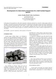
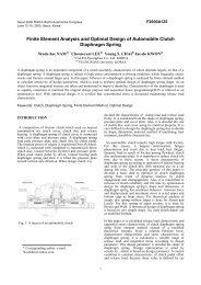
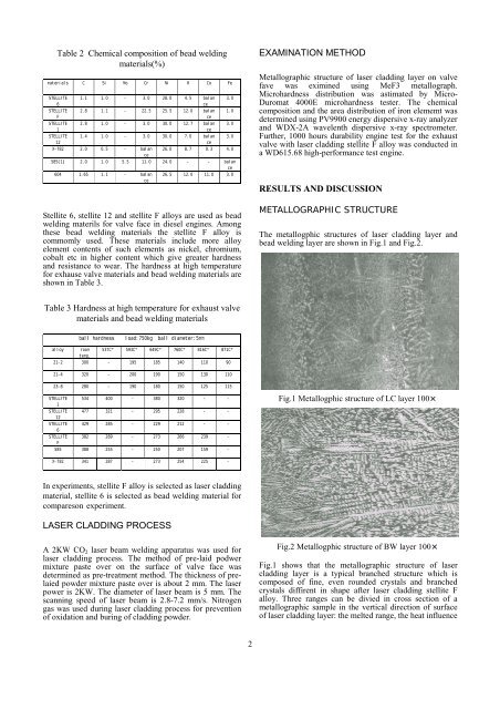
Table 2 Chemical composition <strong>of</strong> bead weldingmaterials(%) <strong>Stellite</strong> 6, stellite 12 and stellite F alloys are used as beadwelding materils for valve face in diesel engines. Amongthese bead welding materials the stellite F alloy iscommomly used. These materials include more alloyelement contents <strong>of</strong> such elements as nickel, chromium,cobalt etc in higher content which give greater hardnessand resistance to wear. The hardness at high temperaturefor exhause valve materials and bead welding materials areshown in Table 3.EXAMINATION METHODMetallographic structure <strong>of</strong> laser cladding layer on valvefave was eximined using MeF3 metallograph.Microhardness distribution was astimated by Micro-Duromat 4000E microhardness tester. The chemicalcomposition and the area distribution <strong>of</strong> iron elememt wasdetermined using PV9900 energy dispersive x-ray analyzerand WDX-2A wavelenth dispersive x-ray spectrometer.Further, 1000 hours durability engine test for the exhaustvalve with laser cladding stellite F alloy was conducted ina WD615.68 high-performance test engine.RESULTS AND DISCUSSIONMETALLOGRAPHIC STRUCTUREThe metallogphic structures <strong>of</strong> laser cladding layer andbead welding layer are shown in Fig.1 and Fig.2.Table 3 Hardness at high temperature for exhaust valvematerials and bead welding materials Fig.1 Metallogphic structure <strong>of</strong> LC layer 100 In experiments, stellite F alloy is selected as laser claddingmaterial, stellite 6 is selected as bead welding material forcompareson experiment.LASER CLADDING PROCESSA 2KW CO 2 laser beam welding apparatus was used forlaser cladding process. The method <strong>of</strong> pre-laid podwermixture paste over on the surface <strong>of</strong> valve face wasdetermined as pre-treatment method. The thickness <strong>of</strong> prelaiedpowder mixture paste over is about 2 mm. The laserpower is 2KW. The diameter <strong>of</strong> laser beam is 5 mm. Thescanning speed <strong>of</strong> laser beam is 2.8-7.2 mm/s. Nitrogengas was used during laser cladding process for prevention<strong>of</strong> oxidation and buring <strong>of</strong> cladding powder.Fig.2 Metallogphic structure <strong>of</strong> BW layer 100Fig.1 shows that the metallographic structure <strong>of</strong> lasercladding layer is a typical branched structure which iscomposed <strong>of</strong> fine, even rounded crystals and branchedcrystals diffirent in shape after laser cladding stellite Falloy. Three ranges can be divied in cross section <strong>of</strong> ametallographic sample in the vertical direction <strong>of</strong> surface<strong>of</strong> laser cladding layer: the melted range, the heat influence2