OPERATOR'S MANUAL NPB-4000/4000C Patient Monitor
OPERATOR'S MANUAL NPB-4000/4000C Patient Monitor
OPERATOR'S MANUAL NPB-4000/4000C Patient Monitor

You also want an ePaper? Increase the reach of your titles
YUMPU automatically turns print PDFs into web optimized ePapers that Google loves.
OPERATOR’S <strong>MANUAL</strong><br />
<strong>NPB</strong>-<strong>4000</strong>/<strong>4000</strong>C <strong>Patient</strong> <strong>Monitor</strong>
Nellcor Puritan Bennett Inc. is an affiliate of Tyco Healthcare. Nellcor, Nellcor<br />
Puritan Bennett, Durasensor, C-LOCK, Oxisensor II, Dura-Y, and the Nellcor<br />
Puritan Bennett knob configuration are trademarks of Nellcor Puritan Bennett Inc.<br />
To obtain information about a warranty, if any, for this product, contact Nellcor’s<br />
Technical Services Department, or your local Nellcor representative.<br />
Covered by one or more of the following U.S. Patents and foreign equivalents:<br />
4,621,643; 4,653,498; 4,700,708; 4,770,179; 4,869,254; 5,368,224 Re. 35,122;<br />
4,928,692; 4,934,372; 5,078,136.
CONTENTS<br />
Figures<br />
Tables<br />
Safety Information ......................................................................1<br />
General Safety Information...................................................1<br />
Introduction.................................................................................5<br />
Intended Use.........................................................................5<br />
About This Manual................................................................5<br />
Controls, Indicators, And Symbols...........................................7<br />
Front Panel ...........................................................................7<br />
Rear Panel ..........................................................................13<br />
Quick Guide To Operation .......................................................15<br />
Features.....................................................................................17<br />
Physical/Mechanical ...........................................................17<br />
Electrical .............................................................................18<br />
Display ................................................................................18<br />
Auxiliary Outputs.................................................................19<br />
Options and Accessories ....................................................19<br />
Setup and Use...........................................................................21<br />
Unpacking and Inspection ..................................................21<br />
Power Cable Connections ..................................................22<br />
Measurement Cable Connections ......................................22<br />
Power On and Self-Test .....................................................24<br />
Set Date and Time..............................................................26<br />
Display and Operation .............................................................29<br />
The Display Configuration...................................................29<br />
Controlling <strong>Monitor</strong> Operation and Display Elements .........35<br />
Alarms and Limits.....................................................................41<br />
General ...............................................................................41<br />
Alarm Priority ......................................................................42<br />
Loss-Of-<strong>Monitor</strong>ing Alarm...................................................43<br />
Visual Alarm Indicators .......................................................43<br />
Audible Alarm Indicators.....................................................44<br />
Setting And Changing Alarm Limits ....................................45<br />
Using The Alarm/Limits Screen ..........................................45<br />
Auto-Set Alarm Limits .........................................................50<br />
Using The Numeric Frame .................................................50<br />
Alarm Limits and Factory-Set Default Values .....................50<br />
Alarm Silence Switch ..........................................................51<br />
Alarm Suspend ...................................................................52<br />
ECG <strong>Monitor</strong>ing ........................................................................55<br />
General ...............................................................................55<br />
ECG Safety Information......................................................55<br />
iii
Contents<br />
iv<br />
Setup Connections............................................................. 57<br />
Controlling ECG Functions Via Numeric Frame ................ 60<br />
Controlling ECG Waveform Via Graphic Frame ................ 61<br />
NIBP <strong>Monitor</strong>ing....................................................................... 65<br />
General .............................................................................. 65<br />
NIBP Safety Information..................................................... 65<br />
Setup Connections............................................................. 67<br />
NIBP Measurement Modes................................................ 68<br />
Controlling NIBP Functions Via Numeric Frame................ 71<br />
SpO2 <strong>Monitor</strong>ing ...................................................................... 73<br />
General .............................................................................. 73<br />
SpO2 Safety Information .................................................... 74<br />
Setup Connection............................................................... 75<br />
Controlling SpO2 Functions Via Numeric Frame ............... 78<br />
Controlling SpO2 Waveform Via Graphic Frame ............... 80<br />
Respiration <strong>Monitor</strong>ing............................................................ 83<br />
General .............................................................................. 83<br />
Respiration Safety Information........................................... 83<br />
Setup Connections............................................................. 84<br />
Controlling Respiration Functions Via Numeric Frame...... 84<br />
Controlling Respiration Waveform Via Graphic Frame...... 86<br />
Temperature <strong>Monitor</strong>ing.......................................................... 89<br />
General .............................................................................. 89<br />
Controlling Temperature Functions Via Numeric Frame ... 90<br />
Trends ....................................................................................... 91<br />
General .............................................................................. 91<br />
Displaying Trend Data........................................................ 92<br />
Selecting A 2-Hour Portion Of The Graphical Trend For<br />
Display:............................................................................... 94<br />
Printing Trend Information (Printer Option Installed): ........ 95<br />
Changing The Vertical Scale Range.................................. 95<br />
Selecting Different Trend Records..................................... 96<br />
Graphical Trend Operation Summary................................ 97<br />
Tabular Trend Data............................................................ 98<br />
Transferring Trends Via RS-232........................................ 98<br />
Printing ..................................................................................... 99<br />
General .............................................................................. 99<br />
Operator Maintenance and Troubleshooting ...................... 103<br />
Error Messages................................................................ 103<br />
Service ............................................................................. 103<br />
Obtaining Technical Assistance....................................... 105<br />
Returning System Components ....................................... 105<br />
Printer Paper Replacement.............................................. 106<br />
Specifications......................................................................... 109<br />
Scope ............................................................................... 109
Contents<br />
FIGURES<br />
General .............................................................................109<br />
Electrical ...........................................................................110<br />
Environmental...................................................................111<br />
Measuring Parameters .....................................................111<br />
Trends...............................................................................115<br />
RS-232 Interface......................................................................117<br />
Overview ...........................................................................117<br />
Cable Connection .............................................................117<br />
Nurse-Call.........................................................................118<br />
Exporting Trend Data........................................................118<br />
Defib Sync Output ..................................................................122<br />
Defib Sync Output.............................................................122<br />
<strong>NPB</strong>-<strong>4000</strong>/C Defib Sync ...................................................122<br />
Optional Accessories.............................................................123<br />
Printer ...............................................................................123<br />
GCX Mount .......................................................................123<br />
Accessory Bag ..................................................................123<br />
Defib Sync Cable ..............................................................123<br />
DC Input Cable .................................................................123<br />
Figure 1: Front Panel, <strong>NPB</strong>-<strong>4000</strong>/C.............................................7<br />
Figure 2: Rear Panel, <strong>NPB</strong>-<strong>4000</strong>/C ...........................................13<br />
Figure 3: <strong>NPB</strong>-<strong>4000</strong>/C <strong>Patient</strong> <strong>Monitor</strong> ......................................17<br />
Figure 4: Copyright Screen........................................................25<br />
Figure 5: Typical Screen for No <strong>Patient</strong> Leads ..........................25<br />
Figure 6: Typical Screen, Valid <strong>Monitor</strong>ed Signals ....................26<br />
Figure 7: A Typical <strong>Monitor</strong>ing Screen.......................................30<br />
Figure 8: Big Numbers Screen ..................................................34<br />
Figure 9: Highlighted ECG Graphic;<br />
Level 1 and Level 2 Menus.........................................37<br />
Figure 10: SpO2 Screen............................................................38<br />
Figure 11: Alarm/Limits Screen Presentation ............................46<br />
Figure 12: Alarm Suspend Screen ............................................52<br />
Figure 13: Standard ECG Leads Placement .............................58<br />
Figure 14: Modified Chest Lead (MCL1) Placement<br />
(if using MCL1, select Lead II) ..................................59<br />
Figure 15: Heart Rate Display ...................................................60<br />
Figure 16: ECG Waveform ........................................................62<br />
Figure 17: NIBP Screen.............................................................71<br />
Figure 18: SpO2 Screen............................................................78<br />
Figure 19: SpO2 Waveform Screen ..........................................80<br />
Figure 20: Respiration Rate Screen ..........................................84<br />
v
Contents<br />
TABLES<br />
Figure 21: Respiration Waveform Screen ................................ 86<br />
Figure 22: Temperature Screen................................................ 90<br />
Figure 23: Graphical and Tabular Trend Screens .................... 93<br />
Figure 24: Accessing the Trend Scroll Capability ..................... 96<br />
Figure 25: Printer Operator Controls......................................... 99<br />
Figure 26: Real-Time Printout................................................. 100<br />
Figure 27: Graphic Trend Printout .......................................... 101<br />
Figure 28: Tabular Trend Printout........................................... 101<br />
Figure 29: Loading Thermal Paper in Printer.......................... 106<br />
Table 1: Front Panel Connectors................................................ 8<br />
Table 2: Switch Panel Symbols .................................................. 8<br />
Table 3: Display Symbols.......................................................... 10<br />
Table 4: Rear Panel Connectors............................................... 13<br />
Table 5: Quick Guide Procedure .............................................. 15<br />
Table 6: Battery Charging Front panel Indications.................... 24<br />
Table 7: <strong>NPB</strong>-<strong>4000</strong>C Color Description .................................... 31<br />
Table 8: <strong>NPB</strong>-<strong>4000</strong>C Battery Icon............................................. 33<br />
Table 9: SpO2 Screen Menus................................................... 39<br />
Table 10: Visual Alarm Flashing Rates..................................... 43<br />
Table 11: Audible Alarm Characteristics................................... 44<br />
Table 12: Alarm/Limits Menu .................................................... 46<br />
Table 13: Auto-Set Limits Formulas ......................................... 50<br />
Table 14: Alarm Limits Ranges and Factory-Set Limits............ 51<br />
Table 15: ECG Lead Color Coding ........................................... 58<br />
Table 16: ECG Lead Pairs (for Standard Leads Placement).... 59<br />
Table 17: Heart Rate Menu....................................................... 60<br />
Table 18: ECG Waveform Menu .............................................. 63<br />
Table 19: Cuff Sizes.................................................................. 67<br />
Table 20: Low Priority NIBP Alarms.......................................... 70<br />
Table 21: NIBP Menu................................................................ 72<br />
Table 22: SpO2 Sensors........................................................... 76<br />
Table 23: SpO2 Menu............................................................... 79<br />
Table 24: SpO2 Waveform ....................................................... 81<br />
Table 25: Respiration Rate Menu ............................................. 85<br />
Table 26: Respiration Waveform Menu .................................... 87<br />
Table 27: Temperature Menu ................................................... 90<br />
Table 28: SpO2 Graphical Trend Menu.................................... 97<br />
Table 29: RS-232 Serial Interface Connections ..................... 117<br />
vi
SAFETY INFORMATION<br />
General Safety Information<br />
GENERAL SAFETY INFORMATION<br />
This section contains important safety information related to<br />
general use of the <strong>NPB</strong>-<strong>4000</strong> monochrome display patient<br />
monitor and <strong>NPB</strong>-<strong>4000</strong>C color display patient monitor. Other<br />
important safety information appears throughout the manual in<br />
sections that relate specifically to the precautionary information.<br />
Read all text surrounding all precautionary information. The<br />
monitors will be referred to as <strong>NPB</strong>-<strong>4000</strong>/C throughout this<br />
manual.<br />
Important! Before use, carefully read this manual,<br />
accessory directions for use, all precautionary information<br />
in boldface type, and specifications.<br />
WARNING: In the USA, do not connect to an electrical<br />
outlet controlled by a wall switch because the device may be<br />
accidentally turned off.<br />
WARNING: As with any medical equipment, carefully<br />
route patient cabling to reduce the possibility of patient<br />
entanglement or strangulation.<br />
Warning: Do not use the <strong>NPB</strong>-<strong>4000</strong>/C patient monitor to<br />
monitor neonates.<br />
WARNING: Explosion hazard. Do not use the <strong>NPB</strong>-<strong>4000</strong>/C<br />
in the presence of flammable anesthetics or gases.<br />
WARNING: The <strong>NPB</strong>-<strong>4000</strong>/C patient monitor is a<br />
prescription device and is to be operated by qualified<br />
personnel only.<br />
WARNING: The user must check the equipment prior to<br />
use and ensure its safe and proper use.<br />
1
Safety Information<br />
WARNING: The <strong>NPB</strong>-<strong>4000</strong>/C is defibrillator proof. It may<br />
remain attached to the patient during defibrillation or while<br />
an electrosurgical unit is in use, but the readings may be<br />
inaccurate during use and shortly thereafter.<br />
WARNING: The <strong>NPB</strong>-<strong>4000</strong>/C is intended only as an<br />
adjunct in patient assessment. It must be used in<br />
conjunction with clinical signs and symptoms.<br />
WARNING: To ensure patient safety, do not place the<br />
monitor in any position that might cause it to fall on the<br />
patient.<br />
WARNING: Disconnect the <strong>NPB</strong>-<strong>4000</strong>/C and sensors<br />
during magnetic resonance imaging (MRI) scanning. Use<br />
during MRI could cause burns or adversely affect the MRI<br />
image or the monitor’s accuracy. Also, to avoid burns,<br />
remove the sensors from the patient before conducting MRI.<br />
WARNING: Do not lift the monitor by the sensor cable,<br />
blood pressure hose, or power cord because the cable, lead,<br />
or cord could disconnect from the monitor, causing the<br />
monitor to drop on the patient.<br />
WARNING: Do not use the <strong>NPB</strong>-<strong>4000</strong>/C to monitor patients<br />
who are linked to heart/lung machines.<br />
WARNING: The <strong>NPB</strong>-<strong>4000</strong>/C may not operate effectively<br />
on patients who are experiencing convulsions or tremors.<br />
WARNING: Occasionally, electrical signals at the heart do<br />
not produce a peripheral pulse. If a patient’s beat-to-beat<br />
pulse amplitude varies significantly (for example, pulsus<br />
alternans, atrial fibrillation, rapid-cycling artificial<br />
ventilator), blood pressure and pulse rate readings can be<br />
erratic and an alternate measuring method should be used<br />
for confirmation.<br />
2
Safety Information<br />
CAUTION: When connecting the <strong>NPB</strong>-<strong>4000</strong>/C patient<br />
monitor to any instrument, verify proper operation before<br />
clinical use. Both the <strong>NPB</strong>-<strong>4000</strong>/C and the instrument<br />
connected to it must be connected to a grounded outlet.<br />
Accessory equipment connected to the monitor’s data<br />
interface must be certified according to IEC Standard 950<br />
for data-processing equipment or IEC Standard 601-1 for<br />
electromedical equipment. All combinations of equipment<br />
must be in compliance with IEC Standard 601-1 system<br />
requirements. Anyone who connects additional equipment<br />
to the signal input or signal output port configures a medical<br />
system and is therefore responsible that the system complies<br />
with the requirements of standard IEC Standard 601-1-1. If<br />
in doubt, consult Nellcor’s Technical Services Department or<br />
your local Nellcor’s representative.<br />
3
[THIS PAGE INTENTIONALLY LEFT BLANK]
INTRODUCTION<br />
Intended Use<br />
About this Manual<br />
INTENDED USE<br />
The purpose and function of the Nellcor <strong>NPB</strong>-<strong>4000</strong>/C patient<br />
monitor is to monitor ECG, heart rate, noninvasive blood<br />
pressure (systolic, diastolic, and mean arterial pressures),<br />
functional arterial oxygen saturation, respiration, and<br />
temperature for adult and pediatric patients in all hospital areas<br />
and hospital-type facilities. It may be used during hospital<br />
transport and in mobile, land-based environments, such as<br />
ambulances.<br />
WARNING: The <strong>NPB</strong>-<strong>4000</strong>/C is intended only as an<br />
adjunct in patient assessment. It must be used in<br />
conjunction with clinical signs and symptoms.<br />
ABOUT THIS <strong>MANUAL</strong><br />
This manual explains how to set up and use the <strong>NPB</strong>-<strong>4000</strong>/C<br />
patient monitor. Important safety information relating to general<br />
use of the <strong>NPB</strong>-<strong>4000</strong>/C appears before this introduction. Other<br />
important safety information is located throughout the text<br />
where applicable. Read the entire manual including the<br />
Safety Information section, before you operate the monitor.<br />
5
[THIS PAGE INTENTIONALLY LEFT BLANK]
CONTROLS, INDICATORS, AND SYMBOLS<br />
Front Panel<br />
Rear Panel<br />
FRONT PANEL<br />
See Figure 1. The front panel controls and indicators are<br />
arranged in groups:<br />
123<br />
1<br />
2<br />
3<br />
4<br />
Figure 1: Front Panel, <strong>NPB</strong>-<strong>4000</strong>/C<br />
1. Display: (the major area of the panel)<br />
2. Switch Panel: (to the right of the display)<br />
3. <strong>Patient</strong> Connectors: (along the bottom of the panel)<br />
4. Control Knob: (the lower right corner of the panel)<br />
7
Controls, Indicators, and Symbols<br />
<strong>Patient</strong> <strong>Monitor</strong>ing Connectors<br />
All patient connections to the <strong>NPB</strong>-<strong>4000</strong>/C are classified as type<br />
CF, which specifies their degree of protection against electrical<br />
shock, and all are rated as defibrillator-proof. Consequently,<br />
each connector is marked with the following symbol.<br />
Symbol for Defibrillator-proof<br />
Type CF Equipment<br />
A unique icon identifying the parameter being monitored<br />
through that connector identifies each connection. Table 1<br />
defines the monitored parameter, connector compatibility, and<br />
icon.<br />
Table 1: Front Panel Connectors<br />
<strong>Monitor</strong>ed<br />
Parameter<br />
ECG<br />
SpO2<br />
Connector Compatibility<br />
Compatible with Nellcor CE-10 ECG<br />
Cables<br />
Compatible with Nellcor sensors and<br />
sensor extension cables<br />
NIBP Compatible with Nellcor SHBP-10 blood<br />
pressure hose<br />
Temperature Compatible with YSI Series 400<br />
temperature probes<br />
Icon<br />
SpO2 %<br />
T<br />
Switch Panel<br />
The symbols identifying the switches and light emitting diode<br />
(LED) indicators on the Switch Panel are described in Table 2.<br />
Table 2: Switch Panel Symbols<br />
Switched/LED<br />
Descriptor Icon Operation<br />
On/Standby Switch<br />
Toggles <strong>NPB</strong>-<strong>4000</strong>/C<br />
between ON and<br />
STANDBY modes<br />
8
Controls, Indicators, and Symbols<br />
Table 2: Switch Panel Symbols<br />
Switched/LED<br />
Descriptor Icon Operation<br />
AC source LED<br />
Indicator<br />
DC source LED<br />
Indicator<br />
NIBP Start/Stop<br />
Switch<br />
NIBP STAT icon<br />
Alarm Silence<br />
Switch<br />
Heart Rate Tone<br />
Volume Switch<br />
When lit, indicates an AC<br />
source connected and<br />
charging the battery<br />
When lit, indicates a DC<br />
source connected and<br />
charging the battery<br />
Toggles between starting<br />
and stopping NIBP<br />
measurement<br />
Indicates STAT mode,<br />
which is activated by<br />
pressing and holding the<br />
NIBP switch for 2 seconds<br />
Temporarily silences the<br />
audible alarm sound for a<br />
pre-set interval<br />
Enables the knob to adjust<br />
volume of the audible tone<br />
Contrast Adjust<br />
Switch<br />
<strong>NPB</strong>-<strong>4000</strong> Pressing switch<br />
causes screen contrast to<br />
change to an average<br />
setting. Also enables the<br />
knob to adjust the contrast<br />
of the display.<br />
<strong>NPB</strong>-<strong>4000</strong>C Pressing<br />
switch causes the screen to<br />
switch to the alternate set of<br />
colors (black background<br />
vs. white background).<br />
9
Controls, Indicators, and Symbols<br />
Display Symbols<br />
The symbols and icons used in the <strong>NPB</strong>-<strong>4000</strong>/C patient monitor<br />
display are described in Table 3.<br />
Table 3: Display Symbols<br />
Heart Rate<br />
/min<br />
SpO2<br />
SpO2 %<br />
SpO2 %<br />
Display - Numeric Frame Symbols<br />
Heart rate icon. Identifies the frame and indicates the<br />
units, beats per second. Always displayed.<br />
Heart rate determined from SpO2 sensor. Displayed<br />
when heart rate is derived from the SpO2 sensor.<br />
Heart rate determined from ECG measurement.<br />
Displayed when heart rate is derived from the ECG<br />
measurement.<br />
Heart rate determined from NIBP measurement.<br />
Displayed when heart rate is derived from the NIBP<br />
measurement.<br />
Heart rate alarm. Displayed when a heart rate alarm<br />
limit has been violated.<br />
Audible Alarm Off. Displayed when audible alarm is<br />
silenced. This icon is in reverse video to indicate that<br />
the audible alarm is temporarily silenced.<br />
SpO2 frame icon. Identifies the frame and indicates<br />
the units (percent). Always displayed.<br />
Pulse amplitude indicator.<br />
SpO2 alarm. Displayed when an SpO2 alarm limit has<br />
been violated.<br />
Audible Alarm Off. Displayed when the audible<br />
alarm is silenced. This icon is in reverse video to<br />
indicate that the audible alarm is temporarily silenced.<br />
10
Controls, Indicators, and Symbols<br />
Table 3: Display Symbols<br />
NIBP<br />
140/90<br />
(106)<br />
mmHg<br />
30<br />
NIBP icon and units of measure<br />
Systolic blood pressure/Diastolic blood pressure<br />
(Mean arterial pressure value)<br />
Auto mode icon and minutes between automatic NIBP<br />
measurement<br />
STAT mode icon appears when STAT mode is active<br />
Display of the initial cuff pressure to be used on the<br />
180 next measurement.<br />
17 Timer icon and minutes since last NIBP measurement<br />
NIBP alarm. Displayed when an NIBP alarm limit has<br />
been violated.<br />
Audible Alarm Off. Displayed when audible alarm is<br />
silenced<br />
Respiration Rate<br />
Respiration icon and units of measure<br />
/min<br />
Respiration alarm. Displayed when a respiration rate<br />
alarm limit has been violated.<br />
Audible Alarm Off. Displayed when audible alarm is<br />
silenced<br />
Temperature<br />
T<br />
C<br />
Temperature icon<br />
Temperature unit of measure, ° C or ° F<br />
Temperature alarm. Displayed when a temperature<br />
alarm limit has been violated.<br />
Audible Alarm Off. Displayed when audible alarm is<br />
silenced.<br />
11
Controls, Indicators, and Symbols<br />
Table 3: Display Symbols<br />
ECG Waveform<br />
Display - Graphic Frame Symbols<br />
ECG icon<br />
0.5 mV<br />
cm<br />
II<br />
SpO2 Waveform<br />
SpO2 %<br />
Size bar, 1 cm high<br />
Size scale<br />
Lead pair<br />
SpO2 icon<br />
Respiration Waveform<br />
( ) Respiration icon<br />
12
REAR PANEL<br />
Controls, Indicators, and Symbols<br />
Five connectors are located on the rear panel of <strong>NPB</strong>-<strong>4000</strong>/C.<br />
See Figure 2 and refer to Table 4. The rear panel includes<br />
threaded standoffs for attaching a GCX mounting system<br />
accessory.<br />
1<br />
2<br />
3<br />
4<br />
5<br />
Figure 2: Rear Panel, <strong>NPB</strong>-<strong>4000</strong>/C<br />
Table 4: Rear Panel Connectors<br />
Figure 2 Description Connector Type Icon<br />
Callout<br />
1 DC Input 2-line; + and ground<br />
2 Equipotential Equipotential<br />
ground<br />
3 Defib Sync 2.5 mm subminature<br />
phone jack<br />
4 AC Input 3-line connector,<br />
IEC 320 receptacle<br />
10 - 16V<br />
5A<br />
100 - 240V ~<br />
50 - 60 Hz<br />
1 A<br />
5 RS-232 I/O DB-9 (male)<br />
RS-232<br />
13
[THIS PAGE INTENTIONALLY LEFT BLANK]
QUICK GUIDE TO OPERATION<br />
Table 5: Quick Guide Procedure<br />
Step Icon Operation<br />
1 … Connect patient cables to front panel connectors<br />
(refer to Setup & Use, page21).<br />
2 … As appropriate, attach cuff, sensor, electrodes,<br />
probe to patient and cables to the monitor (refer<br />
to <strong>Monitor</strong>ing sections pages 55, 65, 73, 83 and<br />
89).<br />
3 Press On/Standby switch to turn monitor on. The<br />
<strong>NPB</strong>-<strong>4000</strong>/C will go through a self-test before<br />
displaying the monitoring screen.<br />
4 Check the alarm limits; adjust if required. Rotate<br />
the knob to highlight the Alarm Limits icon, then<br />
press the knob to view all alarm limits. To<br />
change a limit, rotate the knob until the desired<br />
limit is highlighted, then press the knob. Rotate<br />
the knob again until desired value is obtained.<br />
Repeat as necessary. Upon completion, rotate the<br />
knob to highlight Return, then press the knob to<br />
exit the monitoring screen (refer to Alarms &<br />
Limits, page 41).<br />
— <strong>NPB</strong>-<strong>4000</strong> To adjust the screen contrast, press<br />
the Contrast Adjust switch and rotate the knob to<br />
give the best viewing angle.<br />
<strong>NPB</strong>-<strong>4000</strong>C To adjust color set, press the<br />
Contrast switch until the screen provides an<br />
optimum contrast in the intended setting.<br />
— To adjust the heart rate tone volume, press the<br />
Heart Rate Tone Volume switch and rotate the<br />
knob to give the desired volume.<br />
15
Quick Guide to Operation<br />
Table 5: Quick Guide Procedure<br />
Step Icon Operation<br />
— To initiate a blood pressure measurement, press<br />
the NIBP Start/Stop switch. Press and hold the<br />
NIBP Start/Stop switch for 2 seconds to initiate<br />
STAT mode. A press during any measurement<br />
terminates the measurement and deflates the cuff<br />
(refer to NIBP <strong>Monitor</strong>ing, page 65).<br />
— To temporarily silence an audible alarm, press the<br />
Alarm Silence switch (refer to Alarms & Limits,<br />
page 41).<br />
— To produce a 20-second printout (if optional<br />
printer installed), press Snapshot switch on the<br />
printer. Press the Continuous switch to produce a<br />
continuous printout (refer to Printing, page 99).<br />
5 Press the On/Standby switch to terminate<br />
monitoring and blank the screen.<br />
16
FEATURES<br />
Physical/Mechanical<br />
Electrical<br />
Display<br />
Auxiliary Outputs<br />
Options and Accessories<br />
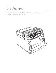
PHYSICAL/MECHANICAL<br />
The <strong>NPB</strong>-<strong>4000</strong>/C patient monitor is a lightweight, compact,<br />
multi-parameter patient monitor measuring 10.6 in x 8.6 in x 6.5<br />
in (26.5 cm x 21.8 cm x 16.5 cm) and weighing 10.8 lb (4.9 kg)<br />
without printer, cable, and accessories. Its carrying handle is<br />
designed for instrument transport while battery-powered<br />
monitoring continues.<br />
The optional printer is installed within the case, adding 0.9 lb<br />
(0.4 kg) to the monitor weight.<br />
Mounting attachments are provided on the case for use with an<br />
optional GCX mounting system. Refer to OPTIONAL<br />
ACCESSORIES section, page 123.<br />
Figure 3: <strong>NPB</strong>-<strong>4000</strong>/C <strong>Patient</strong> <strong>Monitor</strong><br />
17
Features<br />
ELECTRICAL<br />
DISPLAY<br />
The <strong>NPB</strong>-<strong>4000</strong> is powered by an internal battery pack that<br />
provides 4 hours of monitoring from fully charged batteries<br />
(typical, performance is at 25º C, with no printing, and one<br />
NIBP measurement every 15 minutes). The batteries are<br />
continuously recharged when AC or DC power is connected to<br />
the monitor.<br />
The <strong>NPB</strong>-<strong>4000</strong>C is powered by an internal battery pack that<br />
provides 3 hours of monitoring from fully charged batteries<br />
(typical, performance is at 25º C, with no printing, and one<br />
NIBP measurement every 15 minutes). The batteries are<br />
continuously recharged when AC or DC power is connected to<br />
the monitor.<br />
Battery charging is indicated by front panel green LCDs. Two<br />
LCDs are used, one for AC and one for DC. When operating on<br />
batteries, a battery “gauge” icon in the lower part of the display<br />
indicates the battery charge condition.<br />
A warning message appears on the screen and an audible alarm<br />
sounds when the remaining battery power is only enough for 15<br />
minutes of operation. The user should connect the monitor to an<br />
external power source to avoid loss of patient monitoring action.<br />
External power sources may be connected, disconnected, and<br />
reconnected without interrupting the monitoring action.<br />
The <strong>NPB</strong>-<strong>4000</strong> monitoring screen is a monochrome LCD display<br />
that shows all graphic and numeric patient information as well<br />
as alphanumeric status conditions and warning messages.<br />
The <strong>NPB</strong>-<strong>4000</strong>C monitoring screen is a color LCD that shows<br />
all graphic and numeric patient information as well as<br />
alphanumeric status conditions and warning messages.<br />
The graphics, text, and numeric information are grouped into<br />
areas through which the user interacts to control the monitoring<br />
functions and elements of the screen information.<br />
18
Control Knob and Menus<br />
Features<br />
The Control Knob provides user interaction with the display and<br />
the monitor functions.<br />
Rotating and pressing the knob<br />
Rotate<br />
allows a user to navigate and<br />
make changes to the display<br />
elements and monitor<br />
functions. Details of this<br />
interactive operation are<br />
Press<br />
described in the Display &<br />
Operation section, page 29.<br />
AUXILIARY OUTPUTS<br />
The <strong>NPB</strong>-<strong>4000</strong>/C monitor exports trend data via an RS-232 I/O<br />
port. The port also provides the capability for initiating a Nurse<br />
Call upon alarm. Refer to the RS-232 INTERFACE section,<br />
page117, for additional information.<br />
The monitor generates a defibrillator synchronization signal,<br />
Defib Sync. The Defib Sync signal is available at the monitor<br />
rear panel. Refer to the DEFIB SYNC OUTPUT section, page<br />
122.<br />
OPTIONS AND ACCESSORIES<br />
Refer to the OPTIONAL ACCESSORIES section, page 123,<br />
for descriptions of the monitor’s options and accessories.<br />
19
[THIS PAGE INTENTIONALLY LEFT BLANK]
SETUP and USE<br />
Unpacking and Inspection<br />
Power Cable Connections<br />
Measurement Cable Connections<br />
Power On and Self Test<br />
WARNING: The <strong>NPB</strong>-<strong>4000</strong>/C is a prescription device and is<br />
to be operated by qualified personnel only.<br />
WARNING: In the USA, do not connect to an electrical<br />
outlet controlled by a wall switch because the device may be<br />
accidentally turned off.<br />
WARNING: As with all medical equipment, carefully route<br />
patient cabling to reduce the possibility of patient<br />
entanglement or strangulation.<br />
WARNING: Do not use the <strong>NPB</strong>-<strong>4000</strong>/C patient monitor to<br />
monitor neonates.<br />
CAUTION: If the <strong>NPB</strong>-<strong>4000</strong>/C is to be stored for a period of<br />
2 months or longer, notify service personnel to remove the<br />
battery from the monitor prior to storage. Recharge the<br />
battery when the battery has not been recharged for 2 or<br />
more months.<br />
CAUTION: Follow local government ordinances and<br />
recycle instructions regarding disposal or recycling of device<br />
components, including batteries.<br />
UNPACKING AND INSPECTION<br />
The <strong>NPB</strong>-<strong>4000</strong>/C patient monitor is shipped in one carton.<br />
Examine the carton carefully for evidence of damage. Contact<br />
the carrier immediately if any damage is discovered.<br />
Retain all packing material. Refer to the Operator<br />
Maintenance and Troubleshooting section, page 103, for<br />
instructions on returning damaged items.<br />
21
Setup and Use<br />
POWER CABLE CONNECTIONS<br />
AC Power<br />
DC Power<br />
Ensure that the AC outlet is properly grounded and of the<br />
specified voltage and frequency (100-240 VAC, 50-60 Hz).<br />
Connect the AC power cord to the monitor rear panel connector<br />
identified with the AC power icon. See Figure 2, page 13. Use<br />
only a Nellcor supplied power cord. If in doubt about the<br />
integrity of the grounding of the AC power source, the monitor<br />
must be operated from its internal battery.<br />
Connect an external DC power source (10 to 16 volts DC) to the<br />
monitor rear panel connector identified with the DC power icon.<br />
See Figure 2, page 13. Use only a Nellcor DC input cable. The<br />
user must ensure that connection to the external DC supply<br />
meets all applicable safety codes.<br />
MEASUREMENT CABLE CONNECTIONS<br />
WARNING: Do not lift the monitor by the sensor cables,<br />
blood pressure hose, or power cord because the cable, lead,<br />
or cord could disconnect from the monitor, causing the<br />
monitor to drop on the patient.<br />
ECG Cable and Leads<br />
Use only a Nellcor CE-10 ECG cable and LE-Series ECG leads<br />
with the <strong>NPB</strong>-<strong>4000</strong>/C or, or an ECG cable and leads<br />
recommended by Nellcor Technical Services.<br />
Connect the cable to the front panel connector marked with the<br />
ECG icon. See Figure 1, page 7, and refer to Table 1, page 8.<br />
Connect leads to the patient as described in the ECG<br />
<strong>Monitor</strong>ing section, page 55.<br />
22
NIBP Hose and Cuff<br />
Setup and Use<br />
Use only a Nellcor SHBP series hose and SCBP-Series cuff with<br />
the <strong>NPB</strong>-<strong>4000</strong>/C, or a hose and cuff recommended by Nellcor<br />
Technical Services.<br />
Refer to the NIBP <strong>Monitor</strong>ing section, page 65. Select the<br />
appropriate size cuff for the patient. Apply the cuff to the<br />
selected limb. Connect the hose to the front panel connector<br />
marked with the NIBP icon. See Figure 1, page 7, and refer to<br />
Table 1, page 8.<br />
SpO2 Cable and Sensor<br />
Use only Nellcor sensor extension cables and SpO2 sensors with<br />
the <strong>NPB</strong>-<strong>4000</strong>/C.<br />
Refer to the SpO2 <strong>Monitor</strong>ing section, page 73. Select an<br />
appropriate sensor for the patient and desired application. Apply<br />
the sensor to the selected site. Connect the sensor to the cable,<br />
and connect the cable to the front panel connector identified<br />
with the SpO2 icon. See Figure 1, page 7, and refer to Table 1,<br />
page 8.<br />
Temperature Probe<br />
The monitor uses YSI Series 400-compatible temperature<br />
probes. Insert the plug into the compatible jack on the monitor<br />
front panel marked with the temperature icon. See Figure 1,<br />
page 7, and refer to Table 1, page 8. Refer to Temperature<br />
<strong>Monitor</strong>ing section, page 115 for details.<br />
23
Setup and Use<br />
POWER ON AND SELF-TEST<br />
WARNING: If you do not hear the POST (power on<br />
self-test) pass tone, do not use the monitor.<br />
WARNING: Disconnect the <strong>NPB</strong>-<strong>4000</strong>/C and sensors<br />
during magnetic resonance imaging (MRI) scanning. Use<br />
during MRI may cause burns or adversely affect the MRI<br />
image or the monitor’s accuracy<br />
CAUTION: If any indicator or display element does not<br />
light, do not use the monitor. Instead, contact qualified<br />
service personnel, your local Nellcor representative, or the<br />
Nellcor’s Technical Services Department.<br />
Note: The battery may be discharged upon receipt. It will be<br />
fully charged after the first 8 hours the monitor is<br />
connected to an AC or DC power source.<br />
Internal batteries that are charged by <strong>NPB</strong>-<strong>4000</strong>/C connection to<br />
external AC or DC sources supply the monitor power. The front<br />
panel display indicates the status of external power sources, as<br />
summarized in Table 6.<br />
Table 6: Battery Charging Front Panel Indications<br />
External Power<br />
Connections<br />
AC source<br />
DC source<br />
None<br />
AC icon lighted<br />
DC icon lighted<br />
Front panel Indications<br />
Battery “gauge” appears in display.<br />
No LED lit<br />
After patient sensors are connected to their input cables, turn the<br />
monitor ON by pressure the front panel On/Standby switch.<br />
Audible feedback after pressing a front panel switch indicates<br />
that the monitor is processing the action.<br />
24
Setup and Use<br />
A copyright screen appears while the <strong>NPB</strong>-<strong>4000</strong>/C runs a set of<br />
self-diagnostic test routines. See Figure 4. The copyright screen<br />
displays the version of software installed in your unit. Call<br />
Nellcor’s Technical Services for the latest applicable software<br />
and to inquire about software updates.<br />
Copyright 1998 Analogic Corporation. All rights reserved.<br />
V 3.00<br />
Figure 4: Copyright Screen<br />
After power-up diagnostics are completed successfully, the<br />
<strong>NPB</strong>-<strong>4000</strong>/C initiates monitoring operation. If no leads have<br />
been connected to the patient, the display appears similar to that<br />
shown in Figure 5.<br />
/min<br />
0.5 mV<br />
cm<br />
II<br />
SpO2 %<br />
SpO2<br />
( )<br />
NIBP Ð Blocked Hose<br />
( ) /min<br />
T<br />
C<br />
mmHg<br />
/<br />
( )<br />
180<br />
x X Adult 2/14/95 16:34:36<br />
Figure 5: Typical Screen for No <strong>Patient</strong> Leads<br />
25
Setup and Use<br />
When the monitor detects valid signals a typical presentation<br />
with two real-time waveforms and a tabular trend appears. See<br />
Figure 6.<br />
0.5 mV<br />
cm<br />
II<br />
SpO2<br />
( )<br />
/min<br />
85<br />
SpO2 %<br />
97<br />
mmHg 17<br />
140/90<br />
(106)<br />
TREND - 2/14<br />
Time NIBP HB SpO2 RR T<br />
16:17:05 140/90(97) 82 95 11 37.6<br />
180<br />
/min<br />
T<br />
C<br />
30<br />
14<br />
37.8<br />
x X Adult 2/14/95 16:34:36<br />
Figure 6: Typical Screen, Valid <strong>Monitor</strong>ed Signals<br />
If the ON/Standby switch is pressed when in the monitoring<br />
mode, the monitor is placed in the Standby mode, in which:<br />
• The display is blanked<br />
• Trend data taken during the monitoring mode<br />
remains stored in memory<br />
• No further monitoring takes place<br />
• Battery charging continues if the monitor is<br />
connected to an AC or DC power source<br />
SET DATE AND TIME<br />
This procedure will enable you to set the date and time displayed<br />
on the screen and printed on the reports. Setting the date and<br />
time is accomplished by rotating and pressing the control knob.<br />
Note: Read all procedure steps before trying to make any<br />
changes. The display will return to the normal display<br />
screen if the knob is not rotated or pressed for 20<br />
seconds.<br />
26
Setup and Use<br />
1. Rotate the knob to highlight the date time box. A dark<br />
border appears around the frame.<br />
2. Press the knob. Date/Time menu appears.<br />
3. Rotate the knob to highlight Date Format.<br />
4. Press the knob. The date formats appear.<br />
5. Rotate the knob to highlight: mm/dd/yy or dd/mm/yy.<br />
6. Press the knob. The highlighted format appears after the<br />
Date Format menu entry.<br />
7. Rotate the knob to highlight Set Date.<br />
8. Press the knob. A date appears.<br />
9. Rotate the knob to highlight the section of the date to be<br />
changed.<br />
10. Press the knob. Selects the parameter to be changed.<br />
11. Rotate the knob until the desired number is displayed.<br />
12. Press the knob. The desired number is entered into the<br />
monitor.<br />
13. Repeat steps 9 through 12 until the desired date is entered.<br />
14. Rotate the knob to highlight Return.<br />
15. Press the knob. The display returns to the Date/Time menu.<br />
16. Rotate the knob to highlight Set Time.<br />
17. Press the knob. A time appears.<br />
18. Rotate the knob to highlight the section of the time to be<br />
changed.<br />
19. Press the knob. Selects the parameter to be changed.<br />
20. Rotate the knob until the desired number is displayed.<br />
21. Press the knob. The desired number is entered into the<br />
monitor.<br />
22. Repeat steps 18 through 21 until the desired time is entered.<br />
23. Rotate the knob to highlight Return.<br />
24. Press the knob. The display returns to the Date/Time menu.<br />
25. Rotate the knob to highlight Return.<br />
26. Press the knob. The display returns to the normal<br />
monitoring screen.<br />
27
[THIS PAGE INTENTIONALLY LEFT BLANK]
DISPLAY and OPERATION<br />
The Display Configuration<br />
Controlling <strong>Monitor</strong> Operation and Display Elements<br />
WARNING: The <strong>NPB</strong>-<strong>4000</strong>/C is intended only as an<br />
adjunct in patient assessment. It must be used in<br />
conjunction with clinical signs and symptoms.<br />
WARNING: Each time the monitor is used, check alarm<br />
limits to ensure that they are appropriate for the patient<br />
being monitored.<br />
WARNING: The nurse call feature should not be used as<br />
the primary source of alarm notification. The audible and<br />
visual alarms of the monitor, used in conjunction with<br />
clinical signs and symptoms, are the primary source for<br />
notifying medical personnel that an alarm condition exists.<br />
THE DISPLAY CONFIGURATION<br />
General<br />
The display in Figure 7, page 30, is of a typical monitoring<br />
condition with three waveforms. The display is divided into a<br />
number of areas that are further subdivided into frames.<br />
29
Display and Operation<br />
4<br />
3<br />
0.5 mV<br />
cm<br />
II<br />
SpO2<br />
( )<br />
85<br />
SpO2 %<br />
97<br />
mmHg 17<br />
140/90<br />
(106)<br />
/min<br />
30<br />
14<br />
37.8<br />
T<br />
C<br />
NIBP - Blocked Hose<br />
x X Adult 2/14/95 16:34:36<br />
/min<br />
180<br />
1<br />
Figure 7: A Typical <strong>Monitor</strong>ing Screen<br />
1. Numeric Area<br />
2. Gauge Indicates <strong>Monitor</strong> is Using Only Battery<br />
3. Message/menu area<br />
4. Graphic Area<br />
2<br />
Color Display<br />
The <strong>NPB</strong>-<strong>4000</strong>C patient monitor has a color liquid crystal<br />
display (LCD). The <strong>NPB</strong>-<strong>4000</strong>C LCD performs the same<br />
functions as the <strong>NPB</strong>-<strong>4000</strong> LCD except that the display is in<br />
color. The colors are function related as shown in Table 7, page<br />
31.<br />
Note: The Contrast Adjust switch is implemented differently on<br />
the <strong>NPB</strong>-<strong>4000</strong> and the <strong>NPB</strong>-<strong>4000</strong>C. See Table 2, page 8.<br />
30
Display and Operation<br />
Table 7: <strong>NPB</strong>-<strong>4000</strong>C Color Description<br />
Function<br />
ECG/Heart Rate<br />
SpO2<br />
NIBP<br />
Respiratory<br />
Temperature<br />
General Background<br />
Medium Priority Alarm<br />
High Priority Alarm<br />
Battery Icon (normal)<br />
Battery Icon (low battery)<br />
Green<br />
Blue<br />
Red<br />
Yellow<br />
Orange<br />
Color<br />
Black or white<br />
depending on the color<br />
set selected by the<br />
Contrast Adjust switch.<br />
Flash Yellow (numeric<br />
frame background)<br />
Flash Red (numeric<br />
frame background)<br />
Green<br />
Yellow or Red (refer to<br />
Table 8, page 33)<br />
Numeric Area/Frames<br />
The right-hand area of the display is the numeric area and<br />
contains six frames in which numeric values are displayed. Five<br />
of the frames contain suitable icons relating the values to<br />
monitored patient parameters; the sixth frame displays time and<br />
date.<br />
Numeric Frames<br />
From top to bottom, the six numeric frames display the<br />
following:<br />
• Heart Rate in beats/minute<br />
• SpO2 in percent saturation<br />
• NIBP Systolic/Diastolic (Mean Arterial Pressure) in mmHg<br />
• Respiration Rate in breaths/minute<br />
31
Display and Operation<br />
• Temperature in ° C or ° F<br />
• Date and Time: mm/dd/yy or dd/mm/yy for date, and<br />
24-hour format for time<br />
The numeric frames always represent the icon-indicated vital<br />
signs and may not be reassigned, resized, or resequenced.<br />
Graphics Area/Frames<br />
The upper left area is called the graphics area and it contains<br />
three equally sized graphics frames in which real-time<br />
physiological waveforms, graphical trend, or tabular trend data<br />
are displayed.<br />
When the ECG leads are connected to the patient, the top<br />
graphics frame always displays the ECG waveform. In the<br />
remaining two graphic frames, the user may select available<br />
waveforms or trend. The waveforms or trends appearing in the<br />
frames at power-up are factory set, but may be changed by<br />
qualified service personnel with passcode access.<br />
When a menu setup is selected, a single menu frame in which<br />
submenus and selectable parameter values are displayed for user<br />
selection replaces the lower two graphics frames.<br />
Message/Menu Frames<br />
The area below the graphics area is called the Message/Menu<br />
area. The upper of two frames in this area is reserved for<br />
messages. These are in simple language and describe alarm<br />
conditions. The message remains displayed until the problem is<br />
resolved, or it may be cleared by pressing the front panel Alarm<br />
Silence switch. If there is more than one message, each is<br />
displayed for 1 second.<br />
The lower of the two sets of frames in this area is used to show<br />
status icons and to provide menu choices.<br />
32
Status Icons<br />
Display and Operation<br />
Menu Icons<br />
Battery Icon:<br />
The Battery-in-Use icon (at the right end of the frames)<br />
appears whenever the monitor is operating on battery power<br />
alone. The icon is in the form of a “gauge” providing a<br />
graphic indication of remaining battery power. In the <strong>NPB</strong>-<br />
<strong>4000</strong>, the icon flashes when the monitor detects low battery<br />
power. In the <strong>NPB</strong>-<strong>4000</strong>C, the icon is displayed as<br />
indicated in Table 8.<br />
Table 8: <strong>NPB</strong>-<strong>4000</strong>C Battery Icon<br />
Number of Bars<br />
Illuminated<br />
Color Used<br />
Behavior<br />
3, 4, or 5 Green Constant display<br />
2 Yellow Constant display<br />
1 Red Constant display<br />
0 Red Icon flashes and<br />
message displayed<br />
Operating Mode:<br />
The operating mode “Adult” is indicated at the left of the<br />
battery gauge. The Adult operating mode accommodates<br />
both adult and pediatric patients.<br />
There are three icons in the Menu portion of the Message/Menu<br />
area: Alarm/Limits, Big Numbers, and Setup.<br />
Alarm/Limits Icon:<br />
When selected, a menu appears in Frames 2 and 3 of the<br />
Graphics Area. The user may view the current alarm limit<br />
settings, or may modify them.<br />
33
Display and Operation<br />
Big Numbers Icon:<br />
When selected, a Big Numbers display format is generated,<br />
and five numeric frames of monitored patient vital signs are<br />
enlarged and replace the lower two graphic frames and the<br />
six numeric frames. See Figure 8. The time value is moved<br />
to the upper right of the screen.<br />
Setup Icon:<br />
When selected, a menu of general-purpose parameters is<br />
presented in the graphics area. The user activated Nurse<br />
Call signal, if connected. Qualified service personnel can<br />
change the Power-Up Default settings of the monitor by<br />
using the Enter Power-Up Default Menu. This function is<br />
passcode protected, and is further described in Power-Up<br />
Default Settings section, page 35.<br />
0.5 mV<br />
cm<br />
II<br />
85<br />
/min SpO 2 %<br />
mmHg<br />
17 140/90<br />
(106)<br />
30<br />
180<br />
x X Adult<br />
( )<br />
T C<br />
/min<br />
16:34<br />
97<br />
14<br />
37.8<br />
Figure 8: Big Numbers Screen<br />
Big Numbers Screen<br />
The Big Numbers screen provides numeric values that can be<br />
read at a distance, and may be more useful to the clinician. Use<br />
of the Big Numbers presentation has the following<br />
characteristics.<br />
34
Power-Up Default Settings<br />
Display and Operation<br />
• Selecting the “Big Numbers” icon from the<br />
monitoring screen makes access to Big Numbers;<br />
Big Numbers is not a power-up default choice.<br />
• One press or rotation of the knob causes the<br />
<strong>NPB</strong>-<strong>4000</strong>/C to revert to the monitoring screen.<br />
• Any alarm condition causes the <strong>NPB</strong>-<strong>4000</strong>/C to<br />
revert to the monitoring screen.<br />
• No changes to the display are possible.<br />
• The top graphic frame remains identical in size and<br />
content, whether in normal monitoring screen or Big<br />
Numbers screen.<br />
• Single-function buttons in the switch panel operate<br />
normally, with one exception: if Alarm Suspend is<br />
invoked, the normal monitoring screen immediately<br />
replaces Big Numbers.<br />
Each time the <strong>NPB</strong>-<strong>4000</strong>/C is turned on, a number of settings are<br />
automatically configured. These settings include alarm limits,<br />
ECG lead selection, type of waveforms and/or trends presented<br />
in the graphic frames, heart rate tone source, and others. These<br />
settings are known as power-up defaults. Each power-up default<br />
is set at the factory; however, qualified service personnel may<br />
change the factory-set defaults. Instructions for making these<br />
adjustments are found in the <strong>NPB</strong>-<strong>4000</strong>/C service manual.<br />
CONTROLLING MONITOR OPERATION AND DISPLAY<br />
ELEMENTS<br />
Except for actions initiated by pressing a front panel switch,<br />
control of the <strong>NPB</strong>-<strong>4000</strong>/C patient monitor is accomplished by<br />
using the knob to interact with the appropriate area on the<br />
display.<br />
The procedure is the same for all operational and display<br />
changes:<br />
1. Rotate the knob to highlight item to be changed.<br />
35
Display and Operation<br />
2. Press the knob to make the change<br />
The monitoring screen is, in effect,<br />
a high-level menu. Highlighting an<br />
area on the monitoring screen by<br />
rotating the knob, and selecting it<br />
by pressing the knob, will bring up<br />
a Level 1 menu that relates to that<br />
screen area. Once in the Level 1<br />
menu, the same action-pair of<br />
rotating and pressing the knob to<br />
highlight and select a menu item<br />
takes place. The response may be<br />
effective immediately or may bring<br />
up a Level 2 menu that “pops up”<br />
on the screen without removing the<br />
Level 1 menu.<br />
Press<br />
A knob time-out of 20 seconds (no knob action) returns the<br />
display to the monitoring screen.<br />
Rotate<br />
Example of a Change Operation<br />
To change the sweep speed of the ECG waveform presented in<br />
the top graphics frame:<br />
1. ROTATE the knob to highlight the ECG graphics frame. A<br />
dark border appears around that frame.<br />
2. PRESS the knob. The Level 1 menu appears.<br />
3. ROTATE the knob to highlight Sweep Speed. It appears in<br />
reverse video.<br />
4. PRESS the knob. A Level 2 menu appears, and the current<br />
value is highlighted in reverse video.<br />
5. ROTATE the knob to highlight a different value in the list.<br />
6. PRESS the knob. The waveform speed is changed to the<br />
new sweep speed.<br />
7. ROTATE the knob to highlight Return.<br />
8. PRESS the knob to return to the normal monitoring screen.<br />
Figure 9, page 37, illustrates the process described above.<br />
36
1<br />
Display and Operation<br />
5<br />
4<br />
3<br />
2<br />
0.5 mV<br />
cm<br />
II<br />
ECG WAVEFORM MENU<br />
Lead Select (II)<br />
Sweep Speed (25 mm/s)<br />
Size (0.5 Mv/cm)<br />
Pacer Detect (Off)<br />
Extended Low Frequeny Range (Off)<br />
ECG Waveform<br />
SpO2 Waveform<br />
Respiration Waveform<br />
Tabular Trend<br />
HR Graphical Trend<br />
SpO2 Graphical Trend<br />
NIBP Grapical Trend<br />
RR Graphical Trend<br />
Temperature Graphical Trend<br />
Return<br />
12.5 mm/s<br />
25 mm/s<br />
50 mm/s<br />
/min<br />
85<br />
SpO2 %<br />
97<br />
mmHg 17<br />
140/90<br />
(106)<br />
/min<br />
T<br />
C<br />
30<br />
180<br />
14<br />
37.8<br />
x X Adult 2/14/95 16:34:36<br />
Figure 9: Highlighted ECG Graphic;<br />
Level 1 and Level 2 Menus<br />
1. Level 2 Menu 4. Level 1 Menu Items for Current<br />
Graphic Type<br />
2. Closes Menu 5. Highlighted and Selected ECG<br />
Waveform<br />
3. List of Other Graphic<br />
Types<br />
Note: Although other graphic types are listed as possible menu<br />
choices for the top graphics frame, they are not available<br />
when the ECG cable is connected. If an attempt is made<br />
to select another graphic waveform, the following<br />
message block appears “Selection not available.”<br />
Cascading Waveforms<br />
If a waveform already displayed in a graphics frame is also<br />
selected for another frame, then the two frames form a cascaded<br />
waveform, effectively presenting a sample over twice the time<br />
interval of one frame.<br />
The second half of the cascade may be in any frame, and need<br />
not be placed directly under the first frame.<br />
37
Display and Operation<br />
Change Operations Described in Tables<br />
Figure 10 shows an expanded view of a SpO2 waveform frame.<br />
To make a change to this waveform, or put a different type of<br />
graphic in its place, rotate the knob until the SpO2 waveform<br />
frame is highlighted, then press the knob. The relevant menu<br />
appears in the second and third graphic frames.<br />
Table 9, page 39 details the SpO2 waveform menu.<br />
0.5 mV<br />
cm<br />
II<br />
SpO2<br />
( )<br />
( )<br />
85<br />
SpO2 %<br />
97<br />
mmHg 17<br />
140/90<br />
(106)<br />
/min<br />
180<br />
30<br />
14<br />
37.8<br />
T C<br />
NIBP Ð Blocked Hose<br />
x X Adult 2/14/95 16:34:36<br />
/min<br />
2<br />
SpO2<br />
1<br />
1. SpO2 Waveform<br />
2. SpO2 Icon<br />
Figure 10: SpO2 Screen<br />
38
Level 1 Menu Screen<br />
Title: SpO2 WAVEFORM MENU<br />
Sweep Speed<br />
Other graphic type choices:<br />
ECG Waveform<br />
>SpO2 Waveform<br />
Respiration Waveform<br />
Tabular Trend<br />
HR Graphical Trend<br />
SpO2 Graphical Trend<br />
NIBP Graphical Trend<br />
Temperature Graphical<br />
Trend<br />
Return<br />
Table 9: SpO2 Screen Menus<br />
Display and Operation<br />
Level 2 Menu or Response<br />
12.5 mm/s, 25 mm/s, 50 mm/s<br />
No Level 2 menu for these items;<br />
selection of a new graphic type<br />
immediately causes the title and the first<br />
menu items to update to reflect the new<br />
choice.<br />
Exits Level 1 menu immediately,<br />
returns to <strong>Monitor</strong>ing Screen<br />
In this example, the only variable setting for the SpO2 waveform<br />
is Sweep Speed.<br />
Other graphic types may be selected, as listed. An arrow<br />
indicates the current graphic type. The list is the same for all<br />
graphic menus.<br />
The final selection is Return to monitoring screens.<br />
In this example, there is only one variable parameter (sweep<br />
speed. The possible sweep speeds are 12.5, 25, or 50 mm/s.<br />
Note: Table 9, page 39, incorporates a type-font convention to<br />
distinguish what appears on the screen and any<br />
descriptive phrase for segments of the information. The<br />
screen text is presented in bold font; the descriptive text<br />
is in Italics or regular font.<br />
This presentation of the screen frame and the associated tables<br />
of menu choices will be used throughout this manual to<br />
summarize the monitoring operations and screen presentations.<br />
39
[THIS PAGE INTENTIONALLY LEFT BLANK]
ALARMS and LIMITS<br />
General<br />
Alarm Priority<br />
Loss-of-<strong>Monitor</strong>ing Alarm<br />
Visual Alarm Indicators<br />
Audible Alarm Indicators<br />
Setting and Changing Alarm Limits<br />
Using the Alarm/Limits Screen<br />
Auto-Set Alarm Limits<br />
Using the Numeric Frame<br />
Alarm Limits and Factory-Set Default Values<br />
Alarm Silence Switch<br />
Alarm Suspend<br />
GENERAL<br />
WARNING: Do not silence the audible alarm or decrease its<br />
volume if patient safety could be compromised.<br />
WARNING: Each time the monitor is used, check alarm<br />
limits to ensure that they are appropriate for the patient<br />
being monitored.<br />
WARNING: The nurse call feature should not be used as<br />
the primary source of alarm notification. The audible and<br />
visual alarms on the monitor, used in conjunction with<br />
clinical signs and symptoms, are the primary source for<br />
notifying medical personnel that an alarm condition exists.<br />
When the monitor detects certain conditions that require user<br />
attention, the <strong>NPB</strong>-<strong>4000</strong>/C monitor enters an alarm state. The<br />
monitor response is indicated by:<br />
• Visual alarm indicators<br />
• Audible alarm indicators<br />
• Print-on-alarm (if printer installed)<br />
• Identification of out-of-limit vital signs in trend data<br />
• Nurse-call signal (if connected and enabled)<br />
41
Alarms and Limits<br />
ALARM PRIORITY<br />
High Priority:<br />
42<br />
The monitor’s visual and audible responses to a detected alarm<br />
depend on the priority of the alarm; High, Medium, or Low.<br />
A higher priority alarm will supersede a lower priority alarm.<br />
The three categories of alarms are summarized in the following<br />
paragraphs. The text in bold font indicates the message shown<br />
on the screen. Limit alarms do not have messages.<br />
Asystole (4 seconds have passed with no heart beats from<br />
ECG, preceded by detecting valid ECG-derived heart rate<br />
data.)<br />
Loss of Pulse from SpO2 (and no valid ECG)<br />
Medium Priority:<br />
Low Priority:<br />
High/Low Heart Rate limits violated<br />
High/Low SpO2 limits violated<br />
High/Low Sys./Dia./MAP blood pressure limits violated<br />
High/Low Respiration Rate limits violated<br />
High/Low Temperature limits violated<br />
Loss of Respiration Signal<br />
ECG Leads Off<br />
SpO2 Cable/Sensor Disconnect<br />
Loss of Pulse from SpO2 (but there is valid ECG)<br />
Low Battery (alarm commences when the <strong>NPB</strong>-<strong>4000</strong>/C has at<br />
least 15 minutes of operating time remaining)<br />
Temperature Probe Disconnect<br />
NIBP - No Cuff<br />
NIBP - Blocked Hose<br />
NIBP - Artifact<br />
NIBP - Time-Out<br />
Printer Out of Paper
LOSS-OF-MONITORING ALARM<br />
Alarms and Limits<br />
In the event of a high, medium, or low level alarm, the<br />
<strong>NPB</strong>-<strong>4000</strong>/C continues to perform monitoring functions. The<br />
alarms are designed to alert users of patient or instrument<br />
conditions that warrant immediate attention.<br />
A special class of alarms, loss-of-monitoring, occurs when the<br />
<strong>NPB</strong>-<strong>4000</strong>/C cannot continue to monitor because of an error<br />
condition or shutdown because of a low-battery condition.<br />
When a loss-of-monitoring alarm occurs, the <strong>NPB</strong>-<strong>4000</strong>/C emits<br />
a continuous tone until the Alarm Silence switch is pressed.<br />
WARNING: Neither the print-on-alarm nor the nurse-call<br />
signal will be initiated when the monitor detects a loss-ofmonitoring<br />
state.<br />
VISUAL ALARM INDICATORS<br />
When an alarm occurs, the <strong>NPB</strong>-<strong>4000</strong>/C responds with visual<br />
alarm indications. The flashing rates for the three categories of<br />
alarms are shown in Table 10. The <strong>NPB</strong>-<strong>4000</strong>C alarms use<br />
flashing colors to indicate high and medium priority alarm.<br />
Refer to Table 7, page 31.<br />
Table 10: Visual Alarm Flashing Rates<br />
Alarm Category<br />
High Priority<br />
Medium priority<br />
Low priority<br />
Flashing Rate<br />
Two flashes in 1 second<br />
One flash in 2 seconds<br />
Constant (on) (non-flashing)<br />
When a low priority alarm occurs, a non-flashing alarm message<br />
appears in the message area. If more than one low priority alarm<br />
is present, the alarm messages “rotate”. On the <strong>NPB</strong>-<strong>4000</strong>C, the<br />
numeric frame background color will change to a solid yellow<br />
for a low priority alarm.<br />
43
Alarms and Limits<br />
When a medium priority alarm is activated because a parameter<br />
is outside its alarm limits, the out-of-limit numeric value and the<br />
bell icon in the corresponding Numeric Frame flash at the<br />
medium priority rate. Only the numeric frame background color<br />
will flash yellow for a medium priority alarm in the <strong>NPB</strong>-<strong>4000</strong>C.<br />
When the high-priority Asystole alarm occurs, the heart rate<br />
numeric value and the corresponding bell icon flash at the high<br />
priority rate. Only the numeric frame background color will<br />
flash red for a high priority alarm in the <strong>NPB</strong>-<strong>4000</strong>C. A nonflashing<br />
Asystole message appears in the message area and will<br />
override any other messages which may be present (there is no<br />
message “rotation” in this instance).<br />
When the high-priority loss of pulse from SpO2 (with no valid<br />
ECG) alarm occurs, the SpO2 and heart rate numeric values<br />
(which are “0”) and the corresponding bell icons flash at the<br />
high priority rate. Only the numeric frame background color<br />
will flash red for a high priority alarm in the <strong>NPB</strong>-<strong>4000</strong>C. A<br />
non-flashing Loss of Pulse from SpO2 message appears in the<br />
message area and will override any other messages that may be<br />
present (there is no message “rotation” in this instance).<br />
AUDIBLE ALARM INDICATORS<br />
The audible alarm has different tone pitch and on-off beep<br />
patterns for each alarm priority. Refer to Table 11.<br />
Table 11: Audible Alarm Characteristics<br />
Alarm Category Tone Pitch Beep Rate<br />
High priority ~930 Hz ~ 3 beeps per sec.<br />
Medium priority ~750 Hz ~ 1 beep per sec.<br />
Low priority ~500 Hz ~ 1beep per 4 sec.<br />
Loss-of-monitoring ~3300 Hz continuous<br />
Note: Visual alarm indicators cannot be suspended or removed.<br />
Audible alarms may be decreased in volume or silenced<br />
as described in the operational instructions that follow.<br />
44<br />
WARNING: Do not silence the audible alarm or decrease its<br />
volume if patient safety could be compromised.
SETTING AND CHANGING ALARM LIMITS<br />
Alarms and Limits<br />
When the <strong>NPB</strong>-<strong>4000</strong>/C is first turned on, alarm limits are set to<br />
the power-up default values. Qualified service personnel can<br />
change power-up default alarm limits, as described in the<br />
<strong>NPB</strong>-<strong>4000</strong>/C service manual.<br />
The user can change alarm limits from default values, if<br />
necessary, as described below. These changes made by the user<br />
will remain in effect until they are modified again, or until the<br />
<strong>NPB</strong>-<strong>4000</strong>/C is turned off.<br />
WARNING: Each time the monitor is used, check alarm<br />
limits to ensure that they are appropriate for the patient<br />
being monitored.<br />
Alarm limits may be set in two ways:<br />
• Via interaction with a numeric frame that presents<br />
currently measured values of a vital sign, or<br />
• Via interaction with the Alarm/Limits Screen that<br />
presents the limits in all measured parameters at one<br />
time.<br />
USING THE ALARM/LIMITS SCREEN<br />
Rotate the knob until the Alarm/Limits icon (bell and limits<br />
symbol) in the lower left of the monitor screen is highlighted.<br />
Press the knob. The Alarm/Limits menu is displayed. The<br />
monitor’s alarm limits currently in effect for all monitored<br />
parameters are displayed at one time.<br />
Figure 11, page 46, illustrates a typical Alarm/Limits screen.<br />
45
Alarms and Limits<br />
0.5 mV<br />
cm<br />
II<br />
ALARM /LIMITS MENU<br />
Return<br />
Print-on-Alarm (On)<br />
SpO2<br />
/min<br />
85<br />
%<br />
97<br />
/min SpO 2 SYS MAP DIA ( ) T mmHg 17<br />
150 100 200 150 100 50 38.5 140/90<br />
60 90 130 100 60 5 36.0 (106)<br />
180<br />
30<br />
( ) /min<br />
Alarm Volume (6) Silence Period (90 s)<br />
T<br />
C<br />
14<br />
37.8<br />
x X Adult 2/14/95 16:34:36<br />
Figure 11: Alarm/Limits Screen Presentation<br />
Operation of the Alarm/Limits Menu is summarized in Table 12.<br />
Table 12: Alarm/Limits Menu<br />
Selected Level 1<br />
Item<br />
Return<br />
Auto-Set Limits<br />
Level 2 Screen Menu, or<br />
<strong>Monitor</strong> Response When Selected<br />
Exit menu immediately, returns to <strong>Monitor</strong>ing<br />
Screen<br />
Make No Change to Limits: Limits remain for<br />
all parameters as shown.<br />
Auto-Set Now: New limits are calculated<br />
according to formulas described in Table 13, page<br />
50, and replace those on the screen.<br />
46
Table 12: Alarm/Limits Menu<br />
Alarms and Limits<br />
Selected Level 1<br />
Item<br />
Print-on-Alarm<br />
HR Upper/Lower<br />
Limits<br />
HR Audible<br />
Silence<br />
SpO2<br />
Upper/Lower<br />
Limits<br />
SpO2 Audible<br />
Silence<br />
Level 2 Screen Menu, or<br />
<strong>Monitor</strong> Response When Selected<br />
On, Off: Optional printer required. Causes a<br />
20-second “snapshot” printout each time a high or<br />
medium priority out-of-limits alarm condition<br />
occurs. The 20 seconds includes the information<br />
from 10 seconds prior to the alarm event.<br />
Out-of-limits values are identified in the printout<br />
by bracketing them between triangular brackets.<br />
An alarm-initiated printout will interrupt any other<br />
snapshot or trend printing that may be in process.<br />
The interrupted printing will not resume after the<br />
alarm-initiated snapshot has been printed.<br />
Variable: When selected by rotating the knob to<br />
highlight the desired limit, pressing the knob<br />
enables its subsequent rotation to cycle through<br />
possible limit values that appear in place. Pressing<br />
knob places the displayed limit in effect.<br />
On/Off: (Bell icon) Toggling action. When OFF<br />
is selected, permanently silences the audible alarm<br />
for HR limit violations. Bell icon is “slashed”<br />
when OFF is selected.<br />
Variable: When selected by rotating knob to<br />
highlight the desired limit, pressing knob enables<br />
its subsequent rotation to cycle through possible<br />
limit values that appear in place. Pressing knob<br />
places the displayed limit.<br />
On/Off: (Bell icon) Toggling action. When Off<br />
is selected, permanently silences the audible alarm<br />
for SpO2 limit violations. Bell icon is “slashed”<br />
when Off is selected.<br />
47
Alarms and Limits<br />
Table 12: Alarm/Limits Menu<br />
Selected Level 1<br />
Item<br />
SYS<br />
Upper/Lower<br />
Limits<br />
DIA<br />
Upper/Lower<br />
Limits<br />
MAP<br />
Upper/Lower<br />
Limits<br />
NIBP Audible<br />
Silence<br />
RR Upper/Lower<br />
Limits<br />
RR Audible<br />
Silence<br />
Level 2 Screen Menu, or<br />
<strong>Monitor</strong> Response When Selected<br />
Variable: When selected by rotating knob to<br />
highlight the desired limit, pressing knob enables<br />
its subsequent rotation to cycle through possible<br />
limit values that appear in place. Pressing knob<br />
places the displayed limit in effect.<br />
Variable: When selected by rotating knob to<br />
highlight the desired limit, pressing the knob<br />
enables its subsequent rotation to cycle through<br />
possible limit values that appear in place. Pressing<br />
knob places the displayed limit in effect.<br />
Variable: When selected by rotating knob to<br />
highlight the desired limit, pressing the knob<br />
enables its subsequent rotation to cycle through<br />
possible limit values that appear in place. Pressing<br />
knob places the displayed limit in effect.<br />
On/Off: (Bell icon) Toggling action. When OFF<br />
is selected, permanently silences the audible alarm<br />
for NIBP limit violations. Bell icon is “slashed”<br />
when OFF is selected.<br />
Variable: When selected by rotating knob to<br />
highlight the desired limit, pressing the knob<br />
enables its subsequent rotation to cycle through<br />
possible limit values that appear in place. Pressing<br />
knob places the displayed limit in effect.<br />
On/Off: (Bell icon) Toggling action. When Off<br />
is selected, permanently silences the audible alarm<br />
for respiration limit violations and loss of<br />
respiration signal alarm. Bell icon is “slashed”<br />
when Off is selected.<br />
48
Table 12: Alarm/Limits Menu<br />
Alarms and Limits<br />
Selected Level 1<br />
Item<br />
Temperature<br />
Upper/Lower<br />
Limits<br />
Temperature<br />
Audible Silence<br />
Alarm Volume<br />
Silence Period<br />
Level 2 Screen Menu, or<br />
<strong>Monitor</strong> Response When Selected<br />
Variable: When selected by rotating knob to<br />
highlight the desired limit, pressing the knob<br />
enables its subsequent rotation to cycle through<br />
possible limit values that appear in place. Pressing<br />
knob places the displayed limit in effect.<br />
On/Off: (Bell icon) Toggling action. When Off<br />
is selected, permanently silences the audible alarm<br />
for HR limit violations. Bell icon is “slashed”<br />
when Off is selected.<br />
1, 2, 3, 4, 5, 6, 7, 8, 9: Value increases in eight<br />
5 dBA increments from lowest value of 45 dBA in<br />
Step 1 to a maximum of 73 dBA in step 9.<br />
If the Alarm Silence switch on the front panel is<br />
pressed while setting is changed, the alarm will<br />
sound at the volume selected.<br />
30 s, 60 s, 90 s, 120 s: Time is indicated in<br />
seconds.<br />
Pressing the front panel Alarm Silence switch<br />
temporarily silences alarms for the time indicated<br />
in the Silence Period menu item. Alarm state(s) in<br />
effect at the end of the pre-set interval cause the<br />
audible alarm to sound.<br />
Pressing the Alarm Silence switch a second time<br />
(while the silence interval is still in effect) ends the<br />
interval immediately.<br />
On the <strong>NPB</strong>-<strong>4000</strong>, silencing audible alarms does<br />
not affect visual alarm indications.<br />
On the <strong>NPB</strong>-<strong>4000</strong>C, the visual indication of low<br />
priority alarms is cleared by a single press of the<br />
Alarm Silence switch.<br />
49
Alarms and Limits<br />
AUTO-SET ALARM LIMITS<br />
The Auto-Set Limits function allows the user to quickly set<br />
alarm limits based on the patient’s current vital sign values.<br />
When the Auto-Set Limits item is selected from the<br />
Alarm/Limits Menu, the <strong>NPB</strong>-<strong>4000</strong>/C takes each currently<br />
measured vital sign and applies a calculated offset to each value<br />
to generate the new upper and lower alarm limits. Refer to<br />
Table 13.<br />
Table 13: Auto-Set Limits Formulas<br />
Parameter Lower Limit Upper Limit<br />
Heart Rate (HR) (HR) x 0.75 or 30<br />
BPM (whichever is<br />
greater)<br />
(HR) x 1.5 or 250<br />
BPM (whichever is<br />
smaller)<br />
NIBP SYS (SYS) (SYS) x 0.68 + 10 (SYS) x 0.86 + 38<br />
NIBP DIA (DIA) (DIA) x 0.68 + 6 (DIA) x 0.86 + 32<br />
NIBP MAP (MAP) (MAP) x 0.68 + 8 (MAP) x 0.86 + 35<br />
Temperature º C (T) (T) - 0.5 (T) + 0.5<br />
Temperature º F (T) (T) - 0.9 (T) + 0.9<br />
SpO2<br />
Make same as SpO2<br />
power-up default<br />
lower limit.<br />
Make same as SpO2<br />
power-up default<br />
upper limit.<br />
Respiration Rate (RR) (RR) x 0.5 (RR) x 1.5<br />
USING THE NUMERIC FRAME<br />
Alarm limits for interacting with the numeric frame for that<br />
parameter may set any one physiological parameter. These are<br />
described in the chapters covering individual parameter<br />
monitoring.<br />
ALARM LIMITS AND FACTORY-SET DEFAULT VALUES<br />
Table 14, page 51, describes the range and increment values that<br />
are used to change alarm limits. The values set at the factory for<br />
each parameter are also shown.<br />
50
Alarms and Limits<br />
Table 14: Alarm Limits Ranges and Factory-Set Limits<br />
Parameter<br />
Upper Limits<br />
Range/Steps<br />
NIBP 100 to 240<br />
mmHg<br />
5 mmHg steps<br />
NIBP DIA 80 to 180<br />
mmHg<br />
5 mmHg steps<br />
NIBP MAP 90 to 200<br />
mmHg<br />
Temp º C<br />
Temp º F<br />
Heart Rate<br />
Respiration<br />
Rate<br />
33º C to 41º C<br />
0.1º C steps<br />
91º F to 106º F<br />
0.1º F steps<br />
30 to 250 BPM<br />
5 BPM steps<br />
3 to 150 BPM<br />
1 BPM steps<br />
SpO2% 20% to 100%<br />
1% steps<br />
Factory<br />
Defaults<br />
200<br />
mmHg<br />
160<br />
mmHg<br />
180<br />
mmHg<br />
Lower Limits<br />
Range/Steps<br />
60 to 150<br />
mmHg<br />
5 mmHg steps<br />
20 to 120<br />
mmHg<br />
5 mmHg steps<br />
30 to 130<br />
mmHg<br />
5 mmHg steps<br />
38º C 33º C to 41º C<br />
0.1 º C steps<br />
100.6º F 91º F to 106º F<br />
0.1º F steps<br />
170 BPM 30 to 250 BPM<br />
5 BPM steps<br />
40 BPM 3 to 150 BPM<br />
1 BPM steps<br />
100% 20% to 100%<br />
1% steps<br />
Factory<br />
Defaults<br />
70<br />
mmHg<br />
50<br />
mmHg<br />
60<br />
mmHg<br />
36º C<br />
96.6º F<br />
40 BPM<br />
4 BPM<br />
85%<br />
Note: High limits cannot be set less than or equal to the low<br />
limit. Low limits cannot be set greater than or equal to<br />
the high limit.<br />
ALARM SILENCE SWITCH<br />
WARNING: Do not silence the audible alarm or decrease its<br />
volume if patient safety could be compromised.<br />
51
Alarms and Limits<br />
Temporarily silencing the audible alarm is accomplished by<br />
pressing the Alarm Silence switch on the front panel. This<br />
action silences ALL audible alarms for a user-controlled preset<br />
interval. Refer to Silence Period in Table 12, page 46. A<br />
reverse-video, slashed-bell icon appears in each numeric frame<br />
during a temporary silence period.<br />
ALARM SUSPEND<br />
If the Alarm Silence switch is depressed and held for 2 seconds,<br />
the Alarm Suspend condition is initiated. Pressing the Alarm<br />
Silence switch terminates the Alarm Suspend condition.<br />
When Alarm Suspend is initiated, ALL audible alarms and<br />
print-on-alarm functions are disabled. Visual alarms, nurse-call<br />
signal, and identification of out-of-limits vital signs in trend<br />
memory continue to function. Graphic Frames 2 and 3 are<br />
replaced with a prominent warning graphic indicating that the<br />
monitor is in Alarm Suspend. See Figure 12.<br />
0.5 mV<br />
cm<br />
II<br />
ALARM SUSPEND<br />
/min<br />
85<br />
SpO2 %<br />
97<br />
mmHg 17<br />
140/90<br />
(106)<br />
( ) /min<br />
T<br />
C<br />
30<br />
180<br />
14<br />
37.8<br />
x X Adult 2/14/95 16:34:36<br />
Figure 12: Alarm Suspend Screen<br />
WARNING: If an alarm condition (except those leading to a<br />
loss-of-monitoring alarm) occurs while in the Alarm<br />
Suspend state, the only alarm indication at the monitor will<br />
be visual displays related to the alarm condition.<br />
52
Alarms and Limits<br />
During Alarm Suspend, monitoring continues for all parameters;<br />
the numeric values and the top Graphic Frame (typically ECG<br />
waveform) continue to operate normally. Trend memory<br />
operates normally. The single-function buttons continue to<br />
operate normally. No Level 1 or 2 menus may be invoked while<br />
in Alarm Suspend State. Access to the Big Numbers screen is<br />
denied while in the Alarm Suspend condition.<br />
53
[THIS PAGE INTENTIONALLY LEFT BLANK]
ECG MONITORING<br />
GENERAL<br />
General<br />
ECG Safety Information<br />
Setup Connections<br />
Controlling ECG Functions via Numeric Frame<br />
Controlling ECG Waveform via Graphic Frame<br />
The process of depolarization and repolarization of the<br />
myocardium generates electric potentials that are sensed by ECG<br />
electrodes on the skin surface.<br />
These electrodes are typically attached to the patient’s right arm,<br />
left arm, and left leg. The monitor processes and amplifies these<br />
signals and presents the ECG waveform on the screen.<br />
In addition to the acquisition of the QRS complex, the circuitry<br />
performs a number of other functions:<br />
• Computation and display of the heart rate in beats<br />
per minute<br />
• Detection of a “lead off” condition if one of the<br />
electrode connections is disrupted<br />
• Detection of the presence of pacemaker signals<br />
within the waveform complex of the ECG<br />
• Generation of a synchronization pulse for external<br />
use with defibrillators. (The Defib Sync Output is<br />
available at a connector in the rear panel. Refer to<br />
the DEFIB SYNC OUTPUT section, page 122, for<br />
more details.)<br />
• Selection by the user of an extended low frequency<br />
range of signal detection and processing<br />
ECG SAFETY INFORMATION<br />
WARNING: Disconnect the <strong>NPB</strong>-<strong>4000</strong>/C and sensors<br />
during magnetic resonance imaging (MRI) scanning. Use<br />
during MRI could cause burns or adversely affect the MRI<br />
image or the monitor’s accuracy. Also, to avoid burns,<br />
remove the sensors from the patient before conducting MRI.<br />
55
ECG <strong>Monitor</strong>ing<br />
WARNING: Use only a Nellcor CE-10 ECG cable and LE-<br />
Series ECG leads with the <strong>NPB</strong>-<strong>4000</strong>/C or an ECG cable and<br />
lead recommended by Nellcor’s Technical Services. Other<br />
ECG cables and leads may cause improper performance<br />
and/or provide inadequate protection during defibrillation.<br />
WARNING: Ensure that conductive portions of the<br />
electrodes, leads, and cable do not come into contact with<br />
any other conductive parts.<br />
WARNING: The <strong>NPB</strong>-<strong>4000</strong>/C is defibrillator proof. It may<br />
remain attached to the patient during defibrillation or while<br />
an electrosurgical unit is in use, but the readings may be<br />
inaccurate during use and shortly thereafter.<br />
WARNING: Line isolation monitor transients may resemble<br />
actual cardiac waveforms and thus inhibit heart rate alarms.<br />
Such transients may be minimized by proper electrode and<br />
cable placement, as specified in this manual and electrode<br />
directions for use.<br />
WARNING: Do not use damaged ECG leads. Do not<br />
immerse ECG leads completely in water, solvents, or<br />
cleaning solutions because the connectors are not<br />
waterproof. Do not sterilize ECG leads by irradiation,<br />
steam, or ethylene oxide. Refer to the cleaning instructions<br />
in the directions for use for ECG leads.<br />
WARNING: For pacemaker patients, the <strong>NPB</strong>-<strong>4000</strong>/C may<br />
continue to count pacemaker rate during occurrences of<br />
cardiac arrest or some arrhythmias. To reduce the<br />
likelihood of this, ensure that the Pacer Detect setting is ON<br />
in the ECG menu when monitoring such patients. Do not<br />
rely entirely upon the <strong>NPB</strong>-<strong>4000</strong>/C alarms. Keep<br />
pacemeaker patients under close surveillance.<br />
56
ECG <strong>Monitor</strong>ing<br />
WARNING: It is possible for the patient to receive a burn<br />
due to an improperly connected electrosurgical unit.<br />
Additionally, the monitor could be damaged or<br />
measurement errors could occur. Certain steps can be taken<br />
to mitigate against this problem, such as not using small<br />
ECG electrodes, selecting ECG electrode sites remote from<br />
the expected RF paths, using large electrosurgical return<br />
electrodes, and verifying that the electrosurgical return<br />
electrode is properly attached to the patient.<br />
WARNING: ECG cables may be damaged if they are<br />
connected to a patient during defibrillation. Cables that<br />
have been connected to a patient during defibrillation should<br />
be checked for functionality before using again.<br />
SETUP CONNECTIONS<br />
Use only a Nellcor CE-10 ECG cable and LE-Series ECG leads<br />
with the <strong>NPB</strong>-<strong>4000</strong>/C or an ECG cable and leads recommended<br />
by Nellcor’s Technical Services.<br />
1. Connect the ECG cable to the ECG input connector on the<br />
monitor front panel.<br />
2. Connect the ECG leads to the ECG cable.<br />
3. Select the electrodes to be used. Use only one type of<br />
electrode on the same patient to avoid variations in electrical<br />
resistance. For ECG monitoring, Nellcor recommends the<br />
use of silver/silver chloride electrodes. When dissimilar<br />
metals are used for different electrodes, the electrodes may<br />
be subject to large offset potentials due to polarization,<br />
which may be severe enough to prevent obtaining an ECG<br />
trace. Using dissimilar metals may also increase recovery<br />
time after defibrillation.<br />
4. Prepare the electrode sites according to electrode<br />
manufacturer’s instructions. See Figure 13, page 58, and<br />
Figure 14, page 58, for electrode placement configurations.<br />
5. Attach the lead wires to the electrodes.<br />
57
ECG <strong>Monitor</strong>ing<br />
6. Apply the electrodes to the patient as shown in either Figure<br />
13, page 58, or Figure 14, page 59, using the color-code<br />
guide in Table 15, page 31.<br />
7. If Standard ECG Lead Placement is used ( Figure 13), verify<br />
that the desired Lead Selection is active in the ECG<br />
waveform frame. Refer to Table 15. Lead II is best suited<br />
for most monitoring situations.<br />
8. If Modified Chest Lead is used (Figure 14), verify that Lead<br />
II is active in the ECG waveform frame.<br />
Table 15: ECG Lead Color Coding<br />
Lead AHA IEC<br />
Right arm (RA) White Red<br />
Left arm (LA) Black Yellow<br />
Left leg (LL) Red Green<br />
3 1<br />
2<br />
Figure 13: Standard ECG Leads Placement<br />
1 LA 2 LL 3 RA<br />
58
ECG <strong>Monitor</strong>ing<br />
Table 16: ECG Lead Pairs (for Standard Leads Placement)<br />
Lead-Select Option<br />
I<br />
II<br />
III<br />
Electrode Differential<br />
RA ➞ LA<br />
RA ➞ LL<br />
LA ➞ LL<br />
3<br />
1<br />
2<br />
Figure 14: Modified Chest Lead (MCL1) Placement<br />
(if using MCL1, select Lead II)<br />
1 RA 2 LL 3 LA<br />
59
ECG <strong>Monitor</strong>ing<br />
CONTROLLING ECG FUNCTIONS VIA NUMERIC FRAME<br />
0.5 mV<br />
cm<br />
II<br />
SpO2<br />
( )<br />
85<br />
SpO2 %<br />
97<br />
mmHg 17<br />
140/90<br />
(106)<br />
( ) /min<br />
180<br />
30<br />
14<br />
37.8<br />
T C<br />
NIBP Ð Blocked Hose<br />
x X Adult 2/14/95 16:34:36<br />
/min<br />
4<br />
3<br />
/min 1<br />
85<br />
2<br />
Figure 15: Heart Rate Display<br />
1. Units of Measure 3. HR Source Icon<br />
2. HR Value 4. HR Icon<br />
Table 17: Heart Rate Menu<br />
Level 1 Menu Level 2 Menu or Response<br />
Title: Heart Rate Menu<br />
Heart Rate Tone Source SpO2, ECG<br />
Heart rate limits Variable (refer to Table 13,<br />
page 50)<br />
HR alarm silence icon On/Off<br />
Return<br />
Exits Level 1 menu<br />
immediately, returns to<br />
<strong>Monitor</strong>ing Screen<br />
60
ECG <strong>Monitor</strong>ing<br />
The calculated heart rate may be derived from different sources,<br />
as shown by the icon in the frame: ECG, SpO2, or NIBP. The<br />
<strong>NPB</strong>-<strong>4000</strong>/C automatically derives heart rate from ECG<br />
whenever a valid ECG signal is present. If ECG is not present,<br />
but SpO2 is being monitored, the heart rate value is derived from<br />
the SpO2 signal. If neither ECG nor SpO2 is available, heart rate<br />
derived from NIBP will be displayed. If HR is derived from<br />
NIBP, that value will only be displayed for 3 minutes after the<br />
NIBP measurement, then the value is removed from the display.<br />
A short pulse tone will sound, synchronous with each heartbeat.<br />
This heart rate tone may be derived from either of two sources:<br />
SpO2 or ECG, as indicated in Table 17, page 60. When SpO2 is<br />
the source, the pitch varies proportionally with changes in<br />
oxygen saturation, rising as SpO2 increases toward 100%, and<br />
falling as it decreases. If the source is ECG, the heart rate tone<br />
does not change pitch. The volume of the heart rate tone may be<br />
adjusted by pressing the front panel Heart Rate Tone Volume<br />
switch, then turning the knob.<br />
CONTROLLING ECG WAVEFORM VIA GRAPHIC FRAME<br />
When ECG leads are connected to the patient, the top graphic<br />
frame always displays the ECG waveform.<br />
61
ECG <strong>Monitor</strong>ing<br />
0.5 mV<br />
cm<br />
II<br />
SpO2<br />
( )<br />
85<br />
SpO2 %<br />
97<br />
mmHg 17<br />
140/90<br />
(106)<br />
( ) /min<br />
30<br />
14<br />
37.8<br />
T<br />
C<br />
NIBP Ð Blocked Hose<br />
x X Adult 2/14/95 16:34:36<br />
/min<br />
180<br />
4<br />
3<br />
2<br />
0.5 mV<br />
cm<br />
II<br />
1<br />
1. Lead Pair<br />
2. Size Scale<br />
3. Size Bar 1 cm<br />
4. ECG Icon<br />
Figure 16: ECG Waveform<br />
The standard size bar, with a height of 1 cm, serves as a visual<br />
reference for the ECG waveform.<br />
62
Table 18: ECG Waveform Menu<br />
ECG <strong>Monitor</strong>ing<br />
Level 1 Menu<br />
Title: ECG WAVEFORM MENU<br />
Lead Select<br />
Sweep Speed<br />
Size<br />
Pacer Detect<br />
Extended Low Frequency Range<br />
other graphic type choices:<br />
>ECG Waveform<br />
SpO2 Waveform<br />
Respiration Waveform<br />
Tabular Trend<br />
HR Graphic Trend<br />
SpO2 Graphical Trend<br />
NIBP Graphical Trend<br />
RR graphical Trend<br />
Temperature Graphical Trend<br />
Return<br />
Level 2 Menus or Response<br />
I, II, III<br />
12.5 mm/s, 25 mm/s, 50 mm/s<br />
0.5 mV/cm, 1 mV/cm, 2 mV/cm,<br />
4 mV/cm<br />
On, Off<br />
On, Off<br />
No Level 2 menu for these items;<br />
selection of a new graphic type<br />
immediately causes the title and<br />
the first, menu items to update,<br />
reflecting the new choice.<br />
Note: For consistency, the other<br />
display choices are present,<br />
but in frame 1 they can not<br />
be selected as long as ECG<br />
leads are on patient.<br />
Exits Level 1 menu, returns to<br />
<strong>Monitor</strong>ing Screen<br />
Extended Low Frequency Range<br />
When Extended Low Frequency Range is On, the monitor<br />
provides better ST segment resolution. However, the increased<br />
bandwidth may result in low-frequency wander of the ECG<br />
baseline, so it is generally recommended that this feature be kept<br />
Off except when better ST segment resolution is specifically<br />
required.<br />
63
ECG <strong>Monitor</strong>ing<br />
Pacer Detect<br />
Pacer detect should always be On for patients with pacemakers<br />
(refer to safety warning at beginning of chapter). When Pacer<br />
Detect is On, the <strong>NPB</strong>-<strong>4000</strong>/C detects and filters<br />
pacemaker-generated signals so that they will not be measured in<br />
determining a patient’s heart rate. Detected pacemaker signals<br />
will be displayed on the ECG waveform (screen and printout) as<br />
a positive-going spike. <strong>Monitor</strong>ing of non-pacemaker patients is<br />
generally not affected when Pacer Detect is enabled; however, in<br />
some instances if the patient does not have a pacemaker, it may<br />
be desirable to turn the detection function Off so that artifacts in<br />
the waveform will not be mistaken for a pacemaker signal.<br />
ECG Leads Off<br />
The <strong>NPB</strong>-<strong>4000</strong>/C can determine when all three ECG leads are<br />
properly attached to the patient. Should one or more of the leads<br />
come off, or lose good electrical contact, after the monitor has<br />
established that all 3 leads are attached, a low-priority “ECG<br />
Leads Off” alarm will be issued, alerting the caregiver to remedy<br />
the problem.<br />
Occasionally, electromagnetic “noise” may cause the ECG<br />
circuit to electrically “saturate”. If this condition occurs, the<br />
<strong>NPB</strong>-<strong>4000</strong>/C will issue an ECG Leads Off alarm. Occurrence is<br />
rare, and duration should be short. As soon as the condition<br />
ceases, the “ECG Leads Off” alarm will automatically clear.<br />
64
NIBP MONITORING<br />
GENERAL<br />
General<br />
NIBP Safety Information<br />
Setup Connections<br />
NIBP Measurement Modes<br />
Controlling NIBP Functions via Numeric Frame<br />
NIBP processing by the monitor uses the oscillometric<br />
measuring technique. A motorized pump inflates the cuff to<br />
initially blocking the flow of blood in the extremity. Then,<br />
under monitor control, the pressure in the cuff is gradually<br />
reduced, while a pressure transducer detects air pressure and<br />
transmits a signal to the NIBP circuitry.<br />
When the cuff pressure is still above systolic pressure, small<br />
pulses or oscillations in the cuff pressure begin to be sensed by<br />
the transducer. As the cuff continues to deflate, oscillation<br />
amplitude increases to a maximum and then decreases. When<br />
maximum oscillation amplitude occurs, the cuff pressure at that<br />
time is measured as mean arterial pressure (MAP). The systolic<br />
and diastolic pressures are calculated based on analysis of the<br />
oscillation amplitude profile.<br />
NIBP SAFETY INFORMATION<br />
WARNINGS: Use only SCBP Series Blood Pressure Cuffs<br />
and the SHBP-10 Hose or a hose and cuff recommended by<br />
Nellcor’s Technical Services. Using other cuffs or hoses may<br />
result in inaccuracies.<br />
WARNING: Inaccurate measurements may be caused by<br />
incorrect cuff application or use, such as placing the cuff too<br />
loosely on the patient, using the incorrect cuff size, or not<br />
placing the cuff at the same level as the heart, leaky cuff or<br />
hose, and excessive patient motion.<br />
65
NIBP <strong>Monitor</strong>ing<br />
WARNING: The <strong>NPB</strong>-<strong>4000</strong>/C displays results of the last<br />
blood pressure measurement until another measurement is<br />
completed. If a patient’s condition changes during the time<br />
interval between measurements, the <strong>NPB</strong>-<strong>4000</strong>/C will not<br />
detect the change or indicate an alarm condition.<br />
WARNING: As with all automatically inflatable blood<br />
pressure devices, continual cuff measurements can cause<br />
injury to the patient being monitored. Weigh the advantages<br />
of frequent measurement and/or use of stat mode against the<br />
risk of injury.<br />
WARNING: In some cases, rapid, prolonged cycling of an<br />
oscillometric, noninvasive blood pressure monitor cuff has<br />
been associated with any or all of the following: ischemia,<br />
purpura, or neuropathy. Apply the oscillometric cuff<br />
appropriately, according to instructions, and check the cuff<br />
site and cuffed extremity regularly when blood pressure is<br />
measured at frequent intervals or over extended periods of<br />
time.<br />
WARNING: Check the patient’s limb on which the cuff is<br />
applied to assure that circulation is not constricted.<br />
Constriction of circulation is indicated by discoloration of<br />
the extremity. This check should be performed at the<br />
clinician’s discretion at regular intervals based on the<br />
circumstances of the specific situation.<br />
WARNING: Do not place the cuff on an extremity being<br />
used for intravenous infusion or any area where circulation<br />
is compromised or has the potential to be compromised.<br />
WARNING: The blood pressure cuff should not be applied<br />
to the same extremity as the one to which an SpO2 sensor is<br />
attached, since cuff inflation will disrupt SpO2 monitoring<br />
and lead to nuisance alarms.<br />
66
NIBP <strong>Monitor</strong>ing<br />
WARNING: During use on patients, ensure that heavy<br />
objects are not placed on the hose. Avoid crimping or undue<br />
bending, twisting, or entanglement of the hose.<br />
Note: A patient’s vital signs may vary dramatically during<br />
administration of agents affecting the cardiovascular<br />
system, such as those used to raise or lower blood<br />
pressure or raise or lower heart rate.<br />
SETUP CONNECTIONS<br />
Use only a Nellcor SHBP-10 hose and SCBP-Series cuff with<br />
the <strong>NPB</strong>-<strong>4000</strong>/C or a hose and cuff recommended by Nellcor’s<br />
Technical Services.<br />
Measure the patient’s limb and select the proper size cuff. As a<br />
general rule, cuff width should span approximately two-thirds of<br />
the distance between the patient’s elbow and shoulder. Refer to<br />
Table 19.<br />
Table 19: Cuff Sizes<br />
Model Number<br />
SCBR-6R; infant 6 cm (2.4 in.)<br />
SCBP-9R; child/adult<br />
9 cm (3.5 in.)<br />
SCBP-12R; adult 12 cm (4.75<br />
in.)<br />
SCBP-15R; large arm 15 cm<br />
(6.0 in.)<br />
SCBP-18R; thigh 18 cm (7.1 in.)<br />
Limb Circumference Range<br />
10 - 19 cm (4.0 - 7.5 in.)<br />
18 - 26 cm (7.1 - 10.2 in.)<br />
25 - 35 cm (9.9 - 13.8 in.)<br />
33 - 47 cm (13.0 - 18.5 in.)<br />
46 - 66 cm (18.1 - 26.0 in.)<br />
Follow cuff directions for use for applying the cuff to the arm or<br />
thigh. Connect the hose to the front panel connector of the<br />
monitor.<br />
67
NIBP <strong>Monitor</strong>ing<br />
NIBP MEASUREMENT MODES<br />
68<br />
Blood pressure measurements can be made in three modes:<br />
Single<br />
One measurement of each of the three blood pressures<br />
(Systolic/Mean Arterial Pressure/Diastolic) is made and<br />
displayed in the numeric frame.<br />
Automatic<br />
Measurements are made at preset intervals.<br />
STAT<br />
As many measurements as possible are made within a 5-minute<br />
period.<br />
Adjustable Initial Inflation Pressure<br />
The user may select an initial cuff inflation pressure. This is<br />
particularly important with children, since an initial cuff<br />
inflation pressure of 180 mmHg may be uncomfortable, and is<br />
typically higher than it needs to be. The initial inflation pressure<br />
can be set from 100 to 280 mmHg, in intervals of 20 mmHg.<br />
The numeric display in the lower right corner of the NIBP frame<br />
indicates the setting of the initial inflation pressure which will<br />
be used during the next measurement or the instantaneous<br />
pressure in the cuff whenever a measurement is underway.<br />
The initial inflation pressure is determined in one of two ways:<br />
1) Upon power up, and immediately after making a change in the<br />
adjustable initial inflation pressure via the NIBP menu, the<br />
initial inflation pressure is determined by the setting indicated in<br />
the NIBP menu. 2) Immediately after an NIBP reading has been<br />
successfully completed, the initial inflation value is changed to<br />
the just-completed Systolic pressure plus 50 mmHg (rounded off<br />
to the nearest 5 mmHg).<br />
To Initiate a Single Blood Pressure Measurement<br />
Press (momentarily) the front panel NIBP Start/Stop switch. A<br />
single blood pressure measurement will be made.<br />
In addition to displaying the three pressure measurements, the<br />
monitor numeric frame displays a clock icon and a numeric<br />
value, which indicate the elapsed time in minutes since last<br />
taking a measurement.
NIBP <strong>Monitor</strong>ing<br />
The measurements remain in the numeric frame for 60 minutes.<br />
At the end of the 60-minute interval, the measured value and the<br />
icon are removed from the display.<br />
As soon as an NIBP measurement begins, any existing NIBP<br />
values in the numeric frame are removed, and the current,<br />
variable value of the cuff pressure is shown. Systolic, diastolic,<br />
and MAP values are presented when the measurement is<br />
completed.<br />
Absence of valid measurement values because of a low-priority<br />
alarm condition will result in “dashes” in the display.<br />
To Make NIBP Measurements Automatically<br />
Select the desired automatic measurement interval from the<br />
menu, accessed via the NIBP numeric frame. Upon selection,<br />
automatic mode is activated and the initial measurement will be<br />
made “X” minutes later (where “X” is the chosen interval). If a<br />
measurement is desired immediately, press the front panel NIBP<br />
Start/Stop switch.<br />
The NIBP numeric frame will display the AUTO mode icon and<br />
the number of minutes selected for the interval between<br />
measurements. This icon and its numeric value are in addition<br />
to the clock icon and elapsed time since last measurement.<br />
To initiate STAT mode of NIBP operation<br />
Press the front panel NIBP STAT switch and hold it for at least 2<br />
seconds.<br />
While STAT mode is active (5 minutes), the STAT icon appears<br />
in the numeric frame; the clock icon and minutes displays are<br />
removed.<br />
Upon completion of STAT mode, the last measurement made in<br />
that mode is displayed, and both the clock icon and elapsed time<br />
numeric return to the display.<br />
At 60 minutes after completion of the STAT measurements, the<br />
displayed NIBP measurement and the clock icon are removed.<br />
69
NIBP <strong>Monitor</strong>ing<br />
To Stop Blood Pressure Measurements<br />
If a measurement is in process, press the front panel NIBP<br />
Start/Stop switch at any time that you wish to stop the current<br />
measurement and deflate the cuff. If an automatic measurement<br />
is underway, the interval time will be reset.<br />
Low Priority NIBP Alarms<br />
Several conditions may occur to disrupt an NIBP measurement.<br />
Table 20 summarizes the conditions and the recommended<br />
corrective action.<br />
Table 20: Low Priority NIBP Alarms<br />
Low Priority Alarm<br />
Message<br />
NIBP - No Cuff<br />
NIBP - Blocked Hose<br />
NIBP - Artifact<br />
NIBP - Time-Out<br />
Recommended Action<br />
Check to see that the cuff is present. Check the<br />
cuff and hose connections for leaks. Take a<br />
measurement again.<br />
Check to see that the hose is not obstructed or<br />
pinched. Take a measurement again.<br />
<strong>Monitor</strong> detected artifact, usually caused by<br />
patient movement. In the presence of moderate<br />
artifact, the monitor may be able to complete<br />
the measurement and display blood pressure<br />
values. However, in this case the clinician may<br />
wish to repeat the measurement if the values<br />
seem questionable. More severe artifact will<br />
prevent the measurement from being<br />
completed, and dashes will be displayed in the<br />
NIBP numeric frame. In this case, check the<br />
patient, cuff application and cuff orientation.<br />
Take a measurement again.<br />
Measurement could not be completed within<br />
the normal amount of time. Check the patient.<br />
Check the cuff application and orientation.<br />
Take a measurement again.<br />
70
NIBP <strong>Monitor</strong>ing<br />
CONTROLLING NIBP FUNCTIONS VIA NUMERIC FRAME<br />
7<br />
6<br />
5<br />
0.5 mV<br />
cm<br />
II<br />
SpO2<br />
( )<br />
85<br />
SpO2 %<br />
97<br />
mmHg 17<br />
140/90<br />
(106)<br />
( ) /min<br />
30 180<br />
14<br />
37.8<br />
T<br />
C<br />
NIBP Ð Blocked Hose<br />
x X Adult 2/14/95 16:34:36<br />
mmHg 17<br />
140/90<br />
(106)<br />
30<br />
180<br />
1<br />
2<br />
3<br />
4<br />
/min<br />
Figure 17: NIBP Screen<br />
1. Timer Icon-Minutes Since Last Measurement<br />
2. Systolic / Diastolic Values<br />
3. Initial cuff inflation pressure (Note)<br />
4. Auto Mode Icon-Interval In Minutes<br />
5. Mean Arterial Pressure Value<br />
6. NIBP Icon<br />
7. Units of Measure<br />
Note: If measurement is underway, this field displays the<br />
instantaneous pressure in the cuff.<br />
71
NIBP <strong>Monitor</strong>ing<br />
Table 21: NIBP Menu<br />
Title:<br />
Level 1 Menu<br />
NIBP MENU<br />
Level 2 Menus or Response<br />
Automatic Mode Interval Off, 1 min, 3 min, 5 min, 10 min,<br />
15 min, 30 min, 60 min, 90 min<br />
Initial Inflation Pressure 100, 123, 140, 160, 180, 200, 220, 240,<br />
260, 280<br />
S/D/M limits Variable (refer to Table 13, page 50)<br />
Alarm silence icon<br />
On/Off<br />
Return<br />
Exits Level 1 menu immediately,<br />
returns to <strong>Monitor</strong>ing Screen<br />
72
SpO2 MONITORING<br />
GENERAL<br />
General<br />
SpO2 Safety Information<br />
Setup Connections<br />
Controlling SpO2 Functions via Numeric Frame<br />
Controlling SpO2 Waveform via Graphic Frame<br />
Pulse Search Condition<br />
Pulse oximetry works by applying a sensor to a pulsating<br />
arteriolar vascular bed. The sensor contains a dual light source<br />
and photodetector. Bone, tissue, pigmentation, and venous<br />
vessels normally absorb a constant amount of light over time.<br />
The arteriolar bed normally pulsates and absorbs variable<br />
amounts of light during systole and diastole, as blood volume<br />
increases and decreases. The ratio of light absorbed at systole<br />
and diastole is translated into an oxygen saturation<br />
measurement. This measurement is referred to as SpO2.<br />
The <strong>NPB</strong>-<strong>4000</strong>/C utilizes C-LOCK® ECG synchronization to<br />
enhance signal processing during patient movement or poor<br />
perfusion. C-LOCK synchronization utilizes the QRS signal as a<br />
reference point for identifying the oximetry pulse, thus<br />
enhancing “good” pulses and reducing the effect of random<br />
artifacts associated with motion and low perfusion.<br />
The measured SpO2 value from an oximeter may differ from the<br />
saturation value that is calculated from a blood gas partial<br />
pressure of oxygen (PO2). This usually occurs because the<br />
calculated saturation was not appropriately corrected for the<br />
effects of variables that shift the relationship between PO2 and<br />
saturation: pH, temperature, partial pressure of carbon dioxide<br />
(PCO2), 2,3-DPG, and fetal hemoglobin.<br />
73
SpO2 <strong>Monitor</strong>ing<br />
This monitor measures functional saturation — oxygenated<br />
hemoglobin expressed as a percentage of the hemoglobin that<br />
can transport oxygen. It does not detect significant amounts of<br />
dysfunctional hemoglobin, such as carboxyhemoglobin or<br />
methemoglobin. In contrast, hemoximeters such as the IL482<br />
report fractional saturation — oxygenated hemoglobin expressed<br />
as a percentage of all measured hemoglobin, including measured<br />
dysfunctional hemoglobin. To compare functional saturation<br />
measurements to those from an instrument that measures<br />
fractional saturation, fractional measurements must be converted<br />
as follows:<br />
functional saturation =<br />
SpO2 SAFETY INFORMATION<br />
fractional saturation<br />
100 – (% carboxyhemoglobin + % methemoglobin)<br />
x 100<br />
WARNINGS: Use only Nellcor SpO2 sensors for SpO2<br />
measurements. Other SpO2 sensors may cause improper<br />
<strong>NPB</strong>-<strong>4000</strong>/C performance.<br />
WARNING: Tissue damage can be caused by incorrect<br />
application or use of an SpO2 sensor, for example by<br />
wrapping the sensor too tightly or by applying supplemental<br />
tape. Inspect the sensor site as directed in the sensor<br />
directions for use to ensure skin integrity and correct<br />
positioning and adhesion of the sensor.<br />
WARNING: Do not use damaged SpO2 sensors. Do not use<br />
an SpO2 sensor with exposed optical components. Do not<br />
immerse sensor completely in water, solvents, or cleaning<br />
solutions because the sensor and connectors are not<br />
waterproof. Do not sterilize SpO2 sensors by irradiation,<br />
steam, or ethylene oxide. Refer to the cleaning instructions<br />
in the directions for use for reusable SpO2 sensors.<br />
WARNING: Inaccurate readings could result if a sensor is<br />
used incorrectly. Before using a sensor, carefully read and<br />
understand the sensor directions for use.<br />
74
SpO2 <strong>Monitor</strong>ing<br />
WARNING: Inaccurate measurements may be caused by:<br />
• incorrect sensor application or use<br />
• significant levels of dysfunctional hemoglobin (such as<br />
carboxyhemoglobin or methemoglobin)<br />
• intravascular dyes such as indocyanine green or<br />
methylene blue<br />
• exposure to excessive illumination, such as surgical<br />
lamps (especially ones with a xenon light source),<br />
bilirubin lamps, fluorescent lights, infrared heating<br />
lamps, or direct sunlight<br />
• excessive patient movement<br />
• high-frequency electrosurgical interference and<br />
defibrillators<br />
• venous pulsations<br />
• placement of a sensor on an extremity with a blood<br />
pressure cuff, arterial catheter, or intravascular line<br />
• the patient has hypotension, severe vasoconstriction,<br />
severe anemia, or hypothermia<br />
• there is arterial occlusion proximal to the sensor<br />
• the patient is in cardiac arrest or is in shock<br />
WARNING: Loss of pulse signal can occur in any of the<br />
following situations:<br />
• the sensor is too tight<br />
• there is excessive illumination from light sources such as<br />
a surgical lamp, a bilirubin lamp, or sunlight<br />
• a blood pressure cuff is inflated on the same extremity as<br />
the one to which an SpO2 sensor is attached<br />
SETUP CONNECTION<br />
Use only Nellcor sensor extension cables and SpO2 sensors with<br />
the <strong>NPB</strong>-<strong>4000</strong>/C.<br />
When selecting a sensor, consider the patient’s weight and<br />
activity, adequacy of perfusion, availability of sensor sites, need<br />
for sterility, and anticipated duration of monitoring. For more<br />
information, refer to Table 22, page 76, or your local Nellcor<br />
representative.<br />
75
SpO2 <strong>Monitor</strong>ing<br />
Oxygen Transducer<br />
Oxisensor® II<br />
(sterile, single use)<br />
Oxicliq®<br />
(sterile, single, use)<br />
Dura-y®<br />
(nonsterile, reusable)<br />
Durasensor®<br />
(nonsterile, reusable)<br />
Nellcor reflectance sensor<br />
(Nonsterile, limited reuse)<br />
Table 22: SpO2 Sensors<br />
Model<br />
N-25*<br />
I-20<br />
D-20<br />
D-25 (L)<br />
R-15<br />
A<br />
P<br />
N*<br />
I<br />
D-YS*<br />
D-YSE<br />
DS-100A<br />
RS-10<br />
<strong>Patient</strong><br />
Weight<br />
40 kg<br />
3 to 20 kg<br />
10 to 50 kg<br />
>30 kg<br />
>50 kg<br />
>30 kg<br />
10 to 50 kg<br />
40 kg<br />
3 to 20 kg<br />
>1 kg<br />
>30 kg<br />
>40 kg<br />
>40 kg<br />
*Although these Nellcor sensors are specified for use on very<br />
small patients, as well as pediatric and adult patients, the <strong>NPB</strong>-<br />
<strong>4000</strong>/C monitor should NOT be used to monitor neonates.<br />
Observe all warnings and cautions in the directions for use<br />
supplied with these sensors. Carefully apply the sensor to the<br />
patient, as described in the sensor directions for use. The sensor<br />
may be connected directly to the <strong>NPB</strong>-<strong>4000</strong>/C front panel<br />
connector, identified with the SpO2 icon. Typically, however, it<br />
is more convenient to connect the sensor to the monitor by using<br />
a Nellcor SpO2 extension cable. Periodically check to see that<br />
the sensor remains properly positioned on the patient and that<br />
skin integrity is acceptable. Refer to sensor directions for use.<br />
76
SpO2 <strong>Monitor</strong>ing<br />
High ambient light sources such as surgical lights (especially<br />
those with a xenon light source), bilirubin lamps, fluorescent<br />
lights, infrared heating lamps, and direct sunlight can interfere<br />
with the performance of an SpO2 sensor. To prevent<br />
interference from ambient light, ensure that the sensor is<br />
properly applied, and cover the sensor site with opaque material.<br />
Failure to take this action in high ambient light conditions may<br />
result in inaccurate measurements.<br />
If patient movement presents a problem, verify that the sensor is<br />
properly and securely applied; move the sensor to a less active<br />
site; use an adhesive sensor that tolerates some patient motion;<br />
or use a new sensor with fresh adhesive backing.<br />
For reusable sensors, follow the sensor directions for use for<br />
cleaning and reuse. For-single-patient use sensors, use a new<br />
sensor for each patient. Do not sterilize any Nellcor sensor by<br />
irradiation, steam, or ethylene oxide.<br />
77
SpO2 <strong>Monitor</strong>ing<br />
CONTROLLING SpO2 FUNCTIONS VIA NUMERIC FRAME<br />
0.5 mV<br />
cm<br />
II<br />
SpO2<br />
( )<br />
85<br />
SpO2 %<br />
97<br />
mmHg 17<br />
140/90<br />
(106)<br />
( ) /min<br />
30 180<br />
14<br />
37.8<br />
T<br />
C<br />
NIBP - Blocked Hose<br />
x X Adult 2/14/95 16:34:36<br />
/min<br />
4<br />
SpO2 %<br />
1<br />
3<br />
97<br />
2<br />
Figure 18: SpO2 Screen<br />
1. Units of Measure<br />
2. Pulse Amplitude Indicator<br />
3. Audible Alarm Bell Icon<br />
4. SpO2 Icon<br />
78
Table 23: SpO2 Menu<br />
SpO2 <strong>Monitor</strong>ing<br />
Level 1 Menu<br />
Title: SpO2 MENU<br />
SpO2 Response<br />
C-Lock<br />
Level 2 Menus or Response<br />
Slow, Normal, Fast<br />
On, Off<br />
SpO2 limits Variable (refer to Table 13, page 50)<br />
SpO2 alarm silence icon<br />
Return<br />
On/Off (audible on)<br />
Exits Level 1 menu immediately,<br />
returns to <strong>Monitor</strong>ing Screen<br />
SpO2 Response Modes<br />
Normal (Mode 1): Recommended for most clinical situations<br />
in conjunction with C-LOCK ECG synchronization to reduce the<br />
effect of patient motion.<br />
Fast (Mode 2): Useful for special applications such as sleep<br />
studies in which the user desires fast response. Most affected by<br />
patient motion.<br />
Slow (Mode 3): Least affected by patient motion. Should be<br />
used only if Normal mode with C-LOCK does not perform<br />
acceptably. User must be aware that changes in SpO2 are<br />
reported more slowly relative to other modes. Heart rate from<br />
SpO2 is not displayed when slow response mode is enabled.<br />
C-LOCK Operation<br />
When C-LOCK is turned on in the SpO2 menu, C-LOCK<br />
automatically becomes operational any time a valid ECG signal<br />
is detected by the monitor. It is not necessary to turn C-LOCK<br />
off if an ECG signal is not available; the monitor handles this<br />
function automatically.<br />
If the ECG signal is noisy, or of poor quality, SpO2 performance<br />
may be improved by turning C-LOCK off.<br />
79
SpO2 <strong>Monitor</strong>ing<br />
Pulse Amplitude Indicator<br />
The pulse amplitude indicator is a segmented display within the<br />
SpO2 numeric frame that shows the relative strength of the<br />
detected pulse. With each pulse, contiguous segments are<br />
briefly filled; the stronger the pulse, the greater the number of<br />
filled segments.<br />
Pulse Search Condition<br />
The <strong>NPB</strong>-<strong>4000</strong>/C displays a status message “SpO2 Pulse<br />
Search” to indicate that it is attempting to locate the patient’s<br />
pulse. An SpO2 sensor must be connected to the <strong>NPB</strong>-<strong>4000</strong>/C in<br />
order for the SpO2 pulse search condition to occur.<br />
CONTROLLING SpO2 WAVEFORM VIA GRAPHIC FRAME<br />
0.5 mV<br />
cm<br />
II<br />
SpO2<br />
( )<br />
85<br />
SpO2 %<br />
97<br />
mmHg 17<br />
140/90<br />
(106)<br />
( ) /min<br />
180<br />
30<br />
14<br />
37.8<br />
T<br />
C<br />
NIBP Ð Blocked Hose<br />
x X Adult 2/14/95 16:34:36<br />
/min<br />
SpO 2<br />
2 1<br />
Figure 19: SpO2 Waveform Screen<br />
1. SpO2 Waveform<br />
2. SpO2 Icon<br />
80
Table 24: SpO2 Waveform<br />
SpO2 <strong>Monitor</strong>ing<br />
Level 1 Menu<br />
Title: SpO2 WAVEFORM<br />
Sweep speed<br />
ECG Waveform<br />
>SpO2 Waveform<br />
Respiration Waveform<br />
Tabular Trend<br />
HR Graphical Trend<br />
SpO2 Graphical Trend<br />
NIBP Graphical Trend<br />
RR Graphical Trend<br />
Temperature Graphical Trend<br />
Return<br />
.<br />
Level 2 Menus or Response<br />
12.5 mm/s, 25 mm/s, 50 mm/s<br />
No level 2 menu for these items;<br />
selection of a new graphic type<br />
immediately causes the title and<br />
the first menu items to update,<br />
reflecting the new choice.<br />
Exits Level 1 menu immediately,<br />
returns to <strong>Monitor</strong>ing Screen<br />
81
[THIS PAGE INTENTIONALLY LEFT BLANK]
RESPIRATION MONITORING<br />
GENERAL<br />
General<br />
Respiration Safety Information<br />
Setup Connections<br />
Controlling Respiration Functions via Numeric Frame<br />
Controlling Respiration Waveform via Graphic Frame<br />
The patient’s respiration is detected by using two of the three<br />
leads of the ECG electrodes and cable. A low-level excitation<br />
signal is applied to these leads, and the variation of the thoracic<br />
impedance caused by the breathing effort is sensed and<br />
processed for measurement and screen presentation.<br />
Real-time respiratory information is presented as a waveform in<br />
a graphic frame; respiration rate is presented in a numeric frame<br />
and in tabular trend data.<br />
RESPIRATION SAFETY INFORMATION<br />
WARNINGS: The <strong>NPB</strong>-<strong>4000</strong>/C is a respiration rate monitor<br />
only. The <strong>NPB</strong>-<strong>4000</strong>/C should NOT be used for the detection<br />
of apnea. Do not use the <strong>NPB</strong>-<strong>4000</strong>/C to monitor neonates.<br />
WARNING: Keep patients under close surveillance when<br />
monitoring respiration. Respiration signals are relatively<br />
more sensitive to interference from radiated electromagnetic<br />
signals. Thus, it is possible, although unlikely, that radiated<br />
electromagnetic signals from sources external to the patient<br />
and <strong>NPB</strong>-<strong>4000</strong>/C can cause inaccurate respiration readings.<br />
Do not rely entirely on the <strong>NPB</strong>-<strong>4000</strong>/C respiration readings<br />
for patient assessment.<br />
83
Respiration <strong>Monitor</strong>ing<br />
SETUP CONNECTIONS<br />
The respiration signal is acquired using the ECG electrodes,<br />
leads and cable. Refer to the ECG <strong>Monitor</strong>ing section, page<br />
55, for information regarding patient connection.<br />
Respiration monitoring performance may be improved by an<br />
alternate electrode placement, relative to standard ECG<br />
electrode placement.<br />
• Left arm (LA) electrode placement is the left<br />
midaxillary line just below the nipple level.<br />
• Right arm (RA) electrode placement is the right<br />
midaxillary line just below the nipple level.<br />
• Left leg (LL) electrode placement is unchanged<br />
relative to standard ECG lead placement.<br />
The user should be aware that this alternate electrode placement<br />
may change the shape and amplitude of the ECG waveform.<br />
CONTROLLING RESPIRATION FUNCTIONS VIA NUMERIC<br />
FRAME<br />
0.5 mV<br />
cm<br />
II<br />
SpO2<br />
( )<br />
85<br />
SpO2 %<br />
97<br />
mmHg 17<br />
140/90<br />
(106)<br />
( ) /min<br />
30<br />
180<br />
14<br />
37.8<br />
T<br />
C<br />
NIBP Ð Blocked Hose<br />
x X Adult 2/14/95 16:34:36<br />
/min<br />
4<br />
3<br />
( )<br />
/min<br />
14<br />
1<br />
2<br />
Figure 20: Respiration Rate Screen<br />
1. Units of Measure 3. Audible Alarm Bell Icon<br />
2. Measured Value 4. Respiration Icon<br />
84
Table 25: Respiration Rate Menu<br />
Respiration <strong>Monitor</strong>ing<br />
Level 1 Menu<br />
Level 2 Menus or Response<br />
Title: RESPIRATION RATE MENU<br />
Respiration<br />
On, Off<br />
Respiration rate limits Variable (refer to Table 13, page 50)<br />
Respiration rate alarm On/Off (audible on)<br />
Return<br />
Exits Level 1 menu immediately,<br />
returns to <strong>Monitor</strong>ing Screen<br />
Loss of Respiration Signal Alarm<br />
If the <strong>NPB</strong>-<strong>4000</strong>/C patient monitor does not detect a respiration<br />
signal for 40 consecutive seconds, a loss of respiration signal<br />
alarm will be issued. Check the condition of the patient, then<br />
check the condition of the electrodes and lead/cable connections.<br />
The alternate electrode placement described in Setup<br />
Connections, page 84, may improve respiration-monitoring<br />
performance. If poor signal quality persists, the user may<br />
choose to turn Off respiration monitoring, as described below.<br />
CAUTION: When the respiration rate limits audible alarm<br />
has been permanently silenced (the slashed-bell icon is<br />
present), the loss of respiration signal audible alarm will also<br />
be permanently silenced.<br />
Respiration <strong>Monitor</strong>ing On/Off<br />
When respiration monitoring is turned Off in the Respiration<br />
Rate menu, the respiration rate value and respiration waveform<br />
will be blanked, and no respiration monitoring alarms will<br />
function.<br />
85
Respiration <strong>Monitor</strong>ing<br />
CONTROLLING RESPIRATION WAVEFORM VIA GRAPHIC<br />
FRAME<br />
2<br />
( )<br />
0.5 mV<br />
cm<br />
SpO2<br />
( )<br />
85<br />
SpO2 %<br />
97<br />
mmHg 17<br />
140/90<br />
(106)<br />
( ) /min<br />
30<br />
180<br />
14<br />
37.8<br />
T<br />
C<br />
NIBP Ð Blocked Hose<br />
x X Adult 2/14/95 16:34:36<br />
/min<br />
1<br />
Figure 21: Respiration Waveform Screen<br />
1. Respiration Waveform<br />
2. Respiration Icon<br />
86
Level 1 Menu<br />
Table 26: Respiration Waveform Menu<br />
Title: RESPIRATION WAVEFORM MENU<br />
Sweep Speed<br />
other graphic choices:<br />
ECG Waveform<br />
SpO2 Waveform<br />
>Respiration Waveform<br />
Tabular Trend<br />
HR Graphical Trend<br />
SpO2 Graphical Trend<br />
NIPB Graphical Trend<br />
RR Graphical Trend<br />
Temperature Graphical Trend<br />
Return<br />
Respiration <strong>Monitor</strong>ing<br />
Level 2 Menus or Response<br />
6.25 mm/s, 12.5 mm/s, 25 mm/s<br />
No level 2 menu for these items;<br />
selection of a new graphic type<br />
immediately causes the title and<br />
first menu items to update,<br />
reflecting the new choice.<br />
Exits Level 1 menu immediately,<br />
returns to <strong>Monitor</strong>ing Screen<br />
87
[THIS PAGE INTENTIONALLY LEFT BLANK]
TEMPERATURE MONITORING<br />
GENERAL<br />
General<br />
Setup Connections<br />
Controlling Temperature Functions via Numeric Frame<br />
Measurement of patient temperature is accomplished by<br />
processing the signal from a probe containing a resistance<br />
element whose impedance is temperature dependent. These<br />
devices are called thermistors. The signal from the probe is<br />
conditioned by the monitor input circuitry, processed, and the<br />
measured values are shown in the numeric frame.<br />
Setup Connections<br />
The <strong>NPB</strong>-<strong>4000</strong>/C patient monitor is designed to accept signals<br />
from YSI Series 400-compatible thermistor probes.<br />
Interchangeable probes in this series may be used for<br />
esophageal, rectal, skin or surface, or airway temperature<br />
measurement. Follow the directions for use accompanying the<br />
temperature probe. If YSI-compatible probes are not readily<br />
available, contact Nellcor’s Technical Services Department or<br />
your local Nellcor representative. To avoid nuisance limit<br />
alarms, the probe should be affixed to the patient before<br />
connecting to the <strong>NPB</strong>-<strong>4000</strong> and <strong>NPB</strong>-<strong>4000</strong>C front panel<br />
connector.<br />
89
Temperature <strong>Monitor</strong>ing<br />
CONTROLLING TEMPERATURE FUNCTIONS VIA NUMERIC<br />
FRAME<br />
0.5 mV<br />
cm<br />
II<br />
SpO2<br />
( )<br />
85<br />
SpO2 %<br />
97<br />
mmHg 17<br />
140/90<br />
(106)<br />
( ) /min<br />
30<br />
14<br />
37.8<br />
T<br />
C<br />
NIBP Ð Blocked Hose<br />
x X Adult 2/14/95 16:34:36<br />
/min<br />
180<br />
4<br />
37.8<br />
T<br />
o<br />
C 1<br />
3<br />
Figure 22: Temperature Screen<br />
2<br />
1. Measured Value<br />
2. Units of Measure<br />
3. Alarm Bell<br />
4. Temperature Icon<br />
Table 27: Temperature Menu<br />
Level 1 Menu Level 2 Menus or Response<br />
Title: TEMPERATURE MENU<br />
Units<br />
º C, º F<br />
Temperature limits Variable (refer to Table 13, page 50)<br />
Temperature alarm On/Off<br />
Return<br />
Exits Level 1 menu immediately,<br />
returns to <strong>Monitor</strong>ing Screen<br />
90
TRENDS<br />
GENERAL<br />
General<br />
Displaying Trend Data<br />
Selecting a 2-Hour Portion of the Graphical Trend for Display<br />
Printing Trend Information (Printer Option Installed)<br />
Changing the Vertical Scale Range<br />
Selecting Different Trend Records<br />
Graphical Trend Operation Summary<br />
Tabular Trend Data<br />
Transferring Trend via RS-232<br />
Trend Data Storage<br />
Trend Data in graphical or tabular format may be displayed on<br />
the screen, and printed if a printer is installed.<br />
Trend data for all parameters except NIBP is the average of a<br />
20-second sample of the data. For NIBP, the trend data is the<br />
measured values. Twelve (12) hours of trend data is stored in a<br />
nonvolatile memory, and remain in storage when the monitor is<br />
in Standby.<br />
A new record of trend data is started each time the monitor is<br />
turned On. A trend data record is defined as the data from one<br />
power On event to the Standby power event. A date/time<br />
annotation is included at the start of each new record (up to ten<br />
are possible) so the record can be correlated with the patient.<br />
Once trend memory has stored 12 hours of data, the oldest trend<br />
data will be overwritten by new data.<br />
Trend Displays<br />
Trend data is displayed in graphical or tabular format. Trend<br />
information in graphical format for a selected parameter is<br />
shown as a line connecting each of the points representing the<br />
stored 20-second average.<br />
91
Trends<br />
92<br />
NIBP values are shown as vertical lines. The vertical<br />
displacement of the top of the line represents the systolic<br />
pressure, the bottom represents the diastolic pressure, and a<br />
short blank space in the line represents the mean arterial<br />
pressure values. Two hours of graphic trend data are displayed<br />
in one graphic frame.<br />
There is one tabular trend format, containing trend data for all<br />
monitored parameters. The tabular trend data values are<br />
selected each time an NIBP measurement is made or once every<br />
15 minutes, whichever comes first. In the event of an alarm<br />
condition, each 20-second average is shown until the alarm is<br />
corrected. In addition, during the alarm state, the limit(s) being<br />
exceeded are displayed in reverse video. The selected trend<br />
segment is obtained by user interaction with the menu.<br />
DISPLAYING TREND DATA<br />
1. Rotate the knob to highlight the graphic frame in which the<br />
desired trend is to appear.<br />
2. Press the knob.<br />
3. The Level 1 menu for this frame appears in graphics frames<br />
2 and 3.<br />
4. Rotate the knob to highlight the trend description item in the<br />
Level 1 menu.<br />
5. Press the knob. Control is returned to the Level 1 menu.<br />
6. Rotate the knob until the Return message is highlighted.<br />
7. Press the knob.<br />
The display now contains a graphical trend (if selected) or a<br />
tabular trend (if selected) in the previously highlighted graphic<br />
frame location.<br />
Trend Screen Example<br />
In Figure 23, page 93, tabular trend data for all monitored<br />
parameters is displayed in the middle graphics frame; graphical<br />
trend data for the SpO2 parameter is displayed in the bottom<br />
graphics frame.<br />
The newest data appears at the right of graphical trends, and at<br />
the top of tabular trends.
Trends<br />
Additional control of trend operations is obtained by interaction<br />
with the trend display.<br />
0.5 mV<br />
cm<br />
II<br />
TREND - 2/14 8/8<br />
Time NIBP HR SpO2 RR T<br />
16:34:36 140/90(97) 85 97 14 37.8<br />
16:24:36 210/145(169) 84 98 10 38.0<br />
16:14:36 210/150/165 110 96 14 38.1<br />
16:14:36 210/150/165 110 96 14 38.1<br />
16:05:36 155/97(108) 95 95 18 38.9<br />
16:05:36 156/100(112) 100 94 18 39.3<br />
SpO2 - 2 HOURS Press Knob to Exit Scroll 8/8<br />
100<br />
80 %<br />
60<br />
16:34 2/14<br />
/min<br />
85<br />
SpO2 %<br />
97<br />
mmHg 17<br />
140/90<br />
(106)<br />
/min<br />
T<br />
C<br />
30<br />
180<br />
14<br />
37.8<br />
x X Adult 2/14/95 16:34:36<br />
10<br />
TREND - 2/14 8/8<br />
Time NIBP HR SpO2 RR T<br />
16:34:36 140/90(97) 85 97 14 37.8<br />
16:24:36 210/145(169) 84 98 10 38.0<br />
1<br />
9<br />
16:14:36 210/150/165 110 96 14 38.1<br />
16:14:36 210/150/165 110 96 14 38.1<br />
8<br />
16:05:36 155/97(108) 95 95 18 38.9<br />
16:05:36 156/100(112) 100 94 18 39.3<br />
SpO2 - 2 HOURS Press Knob to Exit Scroll 8/8<br />
100<br />
%<br />
80<br />
60<br />
16:34 2/14<br />
2<br />
3<br />
7<br />
6 4<br />
5<br />
Figure 23: Graphical and Tabular Trend Screens<br />
1. Record Number/Total Records 6. Time<br />
2. Units of Measure 7. Two Hours of Trend Data<br />
3. Vertical Axis Range Scale 8. Title<br />
4. Date 9. Five Tabular Rows<br />
5. Time Bar 10. Title<br />
93
Trends<br />
Figure 23 shows the eighth trend record out of eight stored, as<br />
indicated by the 8/8 in the upper right corner of the trend screen<br />
(1/8 would be the current one). The time bar at the right edge of<br />
the trend graph indicates the most recent trend value in the<br />
display and corresponds to the time value displayed below it.<br />
Two hours of graphical trend and five rows of tabular data are<br />
presented in their frames on the screen at any one time. The<br />
capability for viewing more trend data is obtained by using the<br />
scroll function.<br />
SELECTING A 2-HOUR PORTION OF THE GRAPHICAL<br />
TREND FOR DISPLAY:<br />
1. Rotate the knob until the trend graphics frame is highlighted.<br />
The highlighting is shown in Figure 23, page 93.<br />
2. Press the knob.<br />
The Level 1 menu for the waveform trend appears in graphic<br />
frames 2 and 3. (The menu may temporarily obscure the<br />
trend graphics frame.)<br />
The first item is Scroll/Print Trend.<br />
The display is shown in Figure 24, page 96.<br />
3. Rotate the knob to highlight the top menu item Scroll/Print<br />
Trend.<br />
4. Press the knob. The Level 1 menu is removed from the<br />
screen. The knob is now activated.<br />
5. Rotate the knob to scroll through the record.<br />
Counterclockwise rotation moves the 2-hour window<br />
forward in time; clockwise rotation backs up the window.<br />
Each rotational “click” of the knob moves the window in<br />
15-minute increments.<br />
6. After viewing the trend, press the knob again to exit the<br />
scrolling function and return to the Level 1 menu. If no<br />
other changes are desired, select Return to Return to the<br />
normal monitoring screen.<br />
94
PRINTING TREND INFORMATION (PRINTER OPTION<br />
INSTALLED):<br />
Trends<br />
Follow the instructions (above) to enable the knob for scrolling<br />
operation.<br />
At the side-panel printer controls, press the Continuous switch to<br />
print the entire trend record.<br />
Press the Snapshot switch to print only the portion of the record<br />
shown on the screen.<br />
CHANGING THE VERTICAL SCALE RANGE<br />
The user via interaction with a Level 2 menu may select the<br />
range of the vertical axis of a graphical trend. The presentation<br />
can be tailored to show the best resolution, depending upon the<br />
variation of the data in the screen. An example is shown in<br />
Figure 24, page 96.<br />
1. Call the Level 1 menu to the screen, as previously described.<br />
2. Rotate the knob to highlight Range in the menu.<br />
3. Press the knob. The choices of range values for the<br />
measured parameter appears as a pop-up Level 2 menu.<br />
4. Rotate the knob to highlight the desired range.<br />
5. Press the knob. The graphical trend is now scaled for the<br />
selected range, which is also shown along the right-hand<br />
vertical axis.<br />
95
Trends<br />
SpO2 - 2 HOURS Press Knob to Exit Scroll 8/8<br />
100<br />
%<br />
SpO2 GRAPHICAL TREND MENU<br />
Scroll/Print Trend<br />
Range (60-100)<br />
ECG Waveform<br />
SpO2 Waveform<br />
Respiration Waveform<br />
Tabular Trend<br />
HR Graphical Trend<br />
SpO2 Graphical Trend<br />
NIBP Graphical Trend<br />
RR Graphical Trend<br />
Temperature Graphical Trend<br />
Return<br />
80 - 100<br />
60 - 100<br />
0 - 100<br />
/min<br />
85<br />
SpO2 %<br />
97<br />
mmHg 17<br />
140/90<br />
(106)<br />
/min<br />
T<br />
C<br />
180<br />
30<br />
14<br />
37.8<br />
x X Adult 2/14/95 16:34:36<br />
80<br />
60<br />
16:34 10/29<br />
Figure 24: Accessing the Trend Scroll Capability<br />
SELECTING DIFFERENT TREND RECORDS<br />
Only data from one record may appear in the graph at a time.<br />
When a user is scrolling through a previously stored Graphical<br />
Trend and reaches the end of the record, a blank space appears<br />
as the trend data progresses off the graph.<br />
As the knob is turned, the time and date display in the frame is<br />
updated to reflect the time/date of the time bar. If the user is<br />
scrolling “forward” in time, as the end of the record is reached,<br />
the vertical time bar and the time display will follow the last<br />
(newest) data point in that record off the left end of the graph.<br />
The next newest trend record in memory will then appear in the<br />
graph.<br />
If the user is scrolling “back” in time, the process is reversed.<br />
The record number digit updates appropriately as the trend<br />
records are accessed. If the user attempts to scroll beyond the<br />
end of the trend data the monitor will generate a warning tone.<br />
96
GRAPHICAL TREND OPERATION SUMMARY<br />
Trends<br />
Graphical trends may be presented for each of the monitored<br />
vital signs (Heart Rate, Oxygen Saturation, Blood Pressures,<br />
Respiration Rate, and Temperature). The procedures for<br />
presenting the graphical screens, scrolling to select a desired<br />
2-hour segment, changing the vertical range scale, and printing,<br />
are the same for each. The choices for the vertical range scale,<br />
however, are different.<br />
A summary of the user interactions with the screen is shown in<br />
Table 28 for the SpO2 graphical trend frame. The same font<br />
conventions are used as in previous tabular summaries.<br />
Level 1 Menu<br />
Table 28: SpO2 Graphical Trend Menu<br />
Title: SpO2 GRAPHICAL TREND MENU<br />
Level 2 Menus or Response<br />
Scroll/Print Trend<br />
No Level 2 menu. The knob is<br />
activated for scrolling.<br />
Range 0-100, 60-100, 80-100<br />
other graphic type choices:<br />
ECG Waveform<br />
SpO2 Waveform<br />
Respiration Waveform<br />
Tabular Trend<br />
HR Graphical Trend<br />
>SpO2 Graphical Trend<br />
NIPB Graphical Trend<br />
RR Graphical Trend<br />
Temperature Graphical Trend<br />
Return<br />
No Level 2 menu for these items;<br />
selection of a new graphic type<br />
immediately causes the title and<br />
the first menu items to update,<br />
reflecting the new choice.<br />
Exits Level 1 menu immediately,<br />
returns to <strong>Monitor</strong>ing Screen<br />
97
Trends<br />
TABULAR TREND DATA<br />
The procedures for selecting and manipulating tabular trend data<br />
are similar to those for graphical trend data.<br />
• There is only one tabular trend screen display.<br />
• Data from only one record may appear in the frame<br />
at a time.<br />
• Once scrolling is enabled, each rotational “click” of<br />
the knob moves the table by one row.<br />
• When a user is scrolling through a previously stored<br />
Tabular Trend and reaches the end of the record, a<br />
blank space appears as the trend data progresses off<br />
the frame.<br />
• If the user is scrolling “back” in time, the last entry<br />
will exit off the top of the frame. If the user<br />
continues to turn the knob after the last entry has<br />
scrolled off the frame, the next oldest trend record in<br />
memory will appear in the frame, entering from the<br />
bottom side.<br />
• If the user is scrolling “forward” in time, the last<br />
entry will exit off the bottom of the frame. If the<br />
user continues to turn the knob after the last entry<br />
has scrolled off the frame, the next newest trend<br />
record in memory will appear in the frame, entering<br />
from the topside.<br />
• The “record number” digit updates appropriately as<br />
the trend records are accessed.<br />
TRANSFERRING TRENDS VIA RS-232<br />
The entire trend memory can be transferred to an external<br />
computer via the RS-232 interface. Refer to the RS-232<br />
INTERFACE section, page 117, for details.<br />
98
PRINTING<br />
GENERAL<br />
General<br />
SNAPSHOT<br />
When the optional printer is installed, two types of real-time<br />
printed records may be obtained by pressing the appropriate<br />
switch on the printer in the right panel.<br />
A 20-second print, recording real-time graphical and numeric<br />
information beginning with the values 10 seconds before the<br />
print initiation and ending 10 seconds after that event.<br />
In addition, when the Print-on-alarm operation is selected in<br />
the Alarm/Limits menu, a SNAPSHOT printout is made<br />
automatically when a high or medium priority out-of-limits<br />
alarm condition is detected.<br />
CONTINUOUS<br />
A print of real-time graphical and numeric information,<br />
beginning 10 seconds before initiating the action and continuing<br />
until stopped.<br />
1<br />
2<br />
Figure 25: Printer Operator Controls<br />
1. Snapshot Switch<br />
2. Continuous Switch<br />
99
Printing<br />
Pressing either of the two printer buttons can stop printing in<br />
any mode.<br />
The following information is printed in both continuous and<br />
snapshot mode.<br />
• Current numeric values: Heart rate (HR), oxygen<br />
saturation (SpO2), blood pressures (Sys/Dia/MAP),<br />
respiration rate (RR), and temperature (T) are printed<br />
along the top of the paper. Time is printed along the<br />
bottom of the paper.<br />
• Real-time waveforms of the two top graphics frames<br />
on the display.<br />
The user configures the print record by selecting the graphics for<br />
the top two frames and the parameter values of those graphics.<br />
The ECG waveform printout includes: sweep speed, amplitude<br />
scaling (size), and lead configuration (I, II, or III) used for the<br />
measurements. If extended low frequency range is active,<br />
“ELF” will appear on the printout.<br />
NOTE: If the sweep speed in frames 1 and 2 are 6.25, 12.5, or<br />
25 mm/s, the print speed will be 25 mm/s. If the sweep<br />
speed on the display is 50 mm/s, the print speed will be<br />
50 mm/s. If frames 1 and 2 have waveforms of different<br />
speeds, the printout will occur at the faster speed.<br />
11/23/95 ECG<br />
II; HR = 72; SpO2 = 98; NIBP (17:01:45) = 160/73 (96); RR = 19; T = 38.1<br />
II<br />
1 mV/cm<br />
25 mm/s<br />
SpO2<br />
A<br />
17:10:57 A 17:11:00<br />
Figure 26: Real-Time Printout<br />
Print-on-Alarm:<br />
In the Alarm/Limits menu, a “Print-On-Alarm” option is<br />
provided. A snapshot print is initiated upon detection of an<br />
alarm event. Out-of-limits readings are enclosed in brackets.<br />
Instructions for setting this mode are detailed in the Alarms and<br />
Limits section, page 41.<br />
100
Printing<br />
Trend Print<br />
When the knob scrolling function is enabled for a trend frame,<br />
pressing the Snapshot switch on the printer prints the displayed<br />
graphical or tabular trend data. The Snapshot printout contains<br />
only the data shown on the screen at that time.<br />
When the Continuous switch on the printer is pressed, the full<br />
record, as stored to date, is printed.<br />
Only one trend record may be printed at a time.<br />
11/25/95<br />
100<br />
11/23/95<br />
HR 1/min<br />
II; HR = 72; SpO2 = 98; NIBP (17:01:45) = 160/73 (96); RR = 19; T = 38.1<br />
HR 1/min<br />
50<br />
0<br />
A 20:00<br />
A 21:00<br />
A 22:00<br />
A 23:00 A 24:00<br />
A 01:00<br />
Figure 27: Graphic Trend Printout<br />
See Figure 27. Characteristics of the graphical trend printout are<br />
as follows.<br />
• The graphical trend printout begins with the standard<br />
header, followed by the graphical trend itself.<br />
• The title of the trend appears near the top, at the beginning<br />
of the trend.<br />
• The date of the oldest trend data being printed appears in<br />
the upper annotation area at the beginning of the trend.<br />
• The oldest data appears on the left.<br />
11/25/95<br />
11/23/95<br />
00:17:28<br />
00:12:28<br />
00:07:28<br />
00:07:03<br />
00:06:43<br />
00:02:23<br />
23:57:28<br />
HR<br />
1/min<br />
72<br />
72<br />
72<br />
72<br />
72<br />
72<br />
72<br />
SpO2 %<br />
93<br />
93<br />
93<br />
93<br />
93<br />
93<br />
93<br />
Sys<br />
DIA mmHg<br />
157<br />
81<br />
157<br />
81<br />
157<br />
81<br />
---<br />
---<br />
---<br />
---<br />
157<br />
81<br />
157<br />
81<br />
MAP<br />
102<br />
102<br />
102<br />
---<br />
---<br />
102<br />
102<br />
RR<br />
1/min<br />
16<br />
16<br />
16<br />
16<br />
16<br />
16<br />
16<br />
T<br />
38.5<br />
38.5<br />
38.5<br />
38.5<br />
38.5<br />
38.5<br />
38.5<br />
Figure 28: Tabular Trend Printout<br />
See Figure 28, page 101. Characteristics of the tabular trend<br />
printout are as follows.<br />
• The tabular trend printout begins with the standard header<br />
followed by a column of information.<br />
101
Printing<br />
• The date of the newest trend data is at the top of the list,<br />
followed by labels and units for each of the monitored<br />
parameters.<br />
• Next is a series of columns of tabular trend data, each<br />
headed by the time the data in that column was captured.<br />
• Newer data appears to the left of older data.<br />
• Out-of-limits values are enclosed in brackets.<br />
102
OPERATOR MAINTENANCE AND<br />
TROUBLESHOOTING<br />
Error Messages<br />
Service<br />
Obtaining Technical Assistance<br />
Returning System Components<br />
Printer Paper Replacement<br />
ERROR MESSAGES<br />
SERVICE<br />
An Error message is displayed when a malfunction is detected<br />
that prevents further use of the monitor until the malfunction is<br />
corrected.<br />
If the <strong>NPB</strong>-<strong>4000</strong>/C is unable to perform any of its monitoring<br />
functions because of the loss of software control or because of a<br />
detected hardware malfunction, an Error screen appears in which<br />
an error code is presented, along with instruction to refer to this<br />
manual.<br />
Serviceable error codes and other error codes are listed in the<br />
<strong>NPB</strong>-<strong>4000</strong>/C service manual. Contact your service personnel or<br />
record the error code number. Before calling the local Nellcor<br />
representative, make sure that the battery is charged, and that all<br />
power connections are correctly made. If the monitor continues<br />
to present the Error screen, call the Nellcor technical<br />
representative and report the error code number. You will be<br />
advised of the remedial action to be taken.<br />
WARNING: If you are uncertain about the accuracy of any<br />
measurement, check the patients vital signs by alternate<br />
means, then make sure the monitor is functioning correctly.<br />
The <strong>NPB</strong>-<strong>4000</strong>/C requires no routine service other than<br />
cleaning, battery maintenance, and that which is mandated by<br />
the user’s institution. Complete service instructions are<br />
contained in the <strong>NPB</strong>-<strong>4000</strong>/C service manual.<br />
Qualified service personnel in the user’s institution should<br />
perform periodic inspections of the monitor.<br />
103
Operator Maintenance and Troubleshooting<br />
Cleaning<br />
If the institution’s service personnel cannot correct problems,<br />
the <strong>NPB</strong>-<strong>4000</strong>/C should be returned to Nellcor for service.<br />
Contact Nellcor’s Technical Services Department or your local<br />
representative for return instructions.<br />
WARNING: The cover should be removed only by qualified<br />
service personnel. There are no internal user-serviceable<br />
parts.<br />
WARNING: Do not spray, pour, or spill any liquid on the<br />
<strong>NPB</strong>-<strong>4000</strong>/C patient monitor, its accessories, connectors,<br />
switches, or openings in the chassis.<br />
To clean the monitor, dampen a cloth with a commercial,<br />
nonabrasive cleaner and wipe the top, bottom, and front surfaces<br />
lightly. For cables, sensors, and cuffs, follow cleaning<br />
instructions in the directions for use shipped with those<br />
components.<br />
If liquid is accidentally spilled on the monitor, clean and dry<br />
thoroughly before reuse.<br />
If in doubt about monitor safety, refer the unit to qualified<br />
service personnel.<br />
Battery Maintenance<br />
If the <strong>NPB</strong>-<strong>4000</strong>/C patient monitor has not been used one month,<br />
the battery will need charging. To charge the battery, connect<br />
the <strong>NPB</strong>-<strong>4000</strong>/C to an AC outlet or external DC supply as<br />
described in the Setup and Use section, page 21.<br />
Note: Storing the <strong>NPB</strong>-<strong>4000</strong>/C for a long period without<br />
charging the battery may degrade the battery capacity. A<br />
complete battery recharge requires 8 hours.<br />
CAUTION: If the <strong>NPB</strong>-<strong>4000</strong>/C is to be stored for a period of<br />
2 months or longer, notify service personnel to remove the<br />
battery from the monitor prior to storage. Recharge the<br />
battery when the battery has not been recharged for 2 or<br />
more months.<br />
104
Operator Maintenance and Troubleshooting<br />
CAUTION: Follow local government ordinances and<br />
recycle instructions regarding disposal or recycling of device<br />
components, including batteries.<br />
Nellcor recommends that the <strong>NPB</strong>-<strong>4000</strong>/C’s sealed, lead-acid<br />
battery be replaced at 2-year intervals. Refer to the<br />
<strong>NPB</strong>-<strong>4000</strong>/C service manual for battery replacement and general<br />
service instructions. Follow local governing ordinances and<br />
recycling plans regarding disposal or recycling of batteries and<br />
other device components.<br />
OBTAINING TECHNICAL ASSISTANCE<br />
For technical information and assistance, or to order an<br />
<strong>NPB</strong>-<strong>4000</strong>/C service manual, call Nellcor’s Technical Services<br />
Department or your local Nellcor representative. The service<br />
manual includes information required by qualified service<br />
personnel when servicing the <strong>NPB</strong>-<strong>4000</strong>/C.<br />
RETURNING SYSTEM COMPONENTS<br />
Contact Nellcor’s Technical Services Department or your local<br />
Nellcor representative for shipping instructions including a<br />
Returned Goods Authorization number. It is not necessary to<br />
return the sensors or cables. Pack the<br />
<strong>NPB</strong>-<strong>4000</strong>/C patient monitor in its original shipping carton. If<br />
the original carton is not available, use a suitable carton with<br />
appropriate packing material to protect the monitor during<br />
shipping.<br />
Return the <strong>NPB</strong>-<strong>4000</strong>/C by any shipping method that provides<br />
proof of delivery.<br />
105
Operator Maintenance and Troubleshooting<br />
PRINTER PAPER REPLACEMENT<br />
Caution: Use only Nellcor supplied paper.<br />
1<br />
Figure 29: Loading Thermal Paper in Printer<br />
1. Paper Eject Switch<br />
Load thermal paper as described in the following procedure:<br />
1. Open the door at the front of the printer by pressing<br />
the Paper Eject Switch identified in Figure 29. The<br />
door should tilt open.<br />
Note: If the printer’s door does not open<br />
completely, pull it towards you until it is<br />
completely open.<br />
2. Reach in and remove the spent paper core by pulling<br />
it towards you gently.<br />
3. Place a new paper roll between the two round tabs<br />
of the paper holder. Orient the paper roll as shown<br />
in Figure 29.<br />
106
Operator Maintenance and Troubleshooting<br />
Note: The paper roll is easier to load if it is held<br />
horizontally with your thumb underneath it<br />
and your forefinger and/or index finger on<br />
top. Your thumb will hold the loose paper in<br />
place.<br />
4. Pull the paper towards you until approximately 4<br />
inches ( 10.16 cm) of paper have been unrolled.<br />
5. Align the paper with the pinch roller attached to the<br />
printer door.<br />
6. Holding the paper against the roller, close the<br />
printer door.<br />
7. To ensure that the paper is aligned in the slot and<br />
has not been pinched in the door, pull the loose edge<br />
until a few inches of paper is showing. If the paper<br />
will not move, open the door and return to alignment<br />
step 5.<br />
8. The printer should now be ready for operation.<br />
107
[THIS PAGE INTENTIONALLY LEFT BLANK]
SPECIFICATIONS<br />
SCOPE<br />
GENERAL<br />
Scope<br />
General<br />
Electrical<br />
Environmental<br />
Measuring Parameters<br />
Trends<br />
This section includes specifications for the <strong>NPB</strong>-<strong>4000</strong>/C. The<br />
instrument is designed to monitor patient vital signs, including:<br />
electrocardiogram and heart rate, respiration rate, non-invasive<br />
blood pressure, blood oxygen saturation, and temperature. In<br />
addition to displaying the instantaneous values of the measured<br />
parameters, the <strong>NPB</strong>-<strong>4000</strong>/C includes provisions for displaying<br />
waveform data, as well as trends in graphical and tabular format.<br />
The optional printer provides hard copy printing.<br />
Size:<br />
Weight:<br />
Display:<br />
<strong>NPB</strong>-<strong>4000</strong><br />
Screen Type:<br />
Screen Size:<br />
<strong>NPB</strong>-<strong>4000</strong>C<br />
Screen Type:<br />
Screen Size:<br />
Resolution:<br />
10.6 in. x 8.6 in. x 6.5 in.<br />
(26.9 cm x 21.8 cm x 16.5 cm)<br />
excluding handle<br />
10.8 lb (4.9 kg) excluding accessories,<br />
options, cables<br />
Liquid Crystal Display (LCD)<br />
Monochrome, Cold Cathode<br />
Fluorescent Backlit<br />
151 mm x 113 mm (<strong>NPB</strong>-<strong>4000</strong>)<br />
Liquid Crystal Display (LCD) Color,<br />
Cold Cathode Fluorescent Backlit<br />
130 mm x 97 mm (<strong>NPB</strong>-<strong>4000</strong>C)<br />
640 x 480 pixel<br />
109
Specifications<br />
Printer (Optional):<br />
Type:<br />
Weight:<br />
Paper Width:<br />
Speeds:<br />
Thermal<br />
0.9 lb (0.4 kg)<br />
50 mm<br />
25 mm/s and 50 mm/s<br />
ELECTRICAL<br />
Safety Standards: IEC 601-1, UL 2601, Can/CSA C22.2<br />
601.1<br />
Protection Class: Class I, internally powered equipment:<br />
per I.E.C. 601-1, clause 2.2.4<br />
Degree of<br />
Protection:<br />
Mode of<br />
Operation:<br />
Power Sources:<br />
Internal Battery:<br />
Operating Time:<br />
<strong>NPB</strong>-<strong>4000</strong><br />
<strong>NPB</strong>-<strong>4000</strong>C<br />
Type CF: per I.E.C. 601-1, clause<br />
2.2.26<br />
Continuous<br />
6 V, 8 Ampere-Hours;<br />
Type, sealed lead-acid<br />
4 hours typical @ 25° C, no printing,<br />
one NIBP measurement per 15 min.<br />
(fully charged battery)<br />
3 hours typical @ 25° C, no printing,<br />
one NIBP measurement per 15 min.<br />
(fully charged battery)<br />
AC Mains: 100 VAC to 240 VAC, 50 Hz to 60<br />
Hz,<br />
1 A max<br />
DC (External): 10 VDC to 16 VDC, 5A max<br />
110
ENVIRONMENTAL<br />
Specifications<br />
Mechanical Shock: IEC 68-2-27,<br />
100g; 6 msec; three axes,<br />
18 total shocks, non-operating<br />
Mechanical Vibration:<br />
Sinusoidal: IEC 68-2-6,<br />
10 Hz to 58 Hz; 0.15 in.<br />
displacement<br />
58 Hz to 150 Hz; 2 g acceleration<br />
4 min/sweep; 20 sweeps/axis,<br />
non-operating<br />
Thermal:<br />
Operating<br />
0° C to 50° C<br />
Temperature:<br />
Storage<br />
-20° C to 60° C<br />
Temperature:<br />
Humidity:<br />
Operating: 5 % RH to 95% RH, non-condensing<br />
Storage:<br />
5 % RH to 95% RH, non-condensing<br />
Water Resistance: IEC 529 Classification IPX1<br />
(Protected against vertically dripping<br />
water)<br />
Altitude:<br />
0 ft – 10,000 ft (operating)<br />
Electromagnetic<br />
Compatibility:<br />
MEASURING PARAMETERS<br />
ECG Measurement/Display<br />
Radiated and conducted<br />
electromagnetic energy per<br />
CISPR 11, Class B<br />
Heart Rate Range:<br />
Heart Rate Accuracy:<br />
Bandwidth Normal<br />
<strong>Monitor</strong>ing:<br />
20 BPM to 250 BPM<br />
±5 BPM<br />
0.5 Hz to 40 Hz<br />
111
Specifications<br />
Bandwidth, Extended Low<br />
Frequency Response:<br />
Leads:<br />
Display Sweep Speeds:<br />
Pacemaker Detection:<br />
0.05 Hz to 40 Hz<br />
(User selectable)<br />
3 Lead, user selectable<br />
12.5 mm/sec, 25 mm/sec, and<br />
50 mm/sec<br />
Indicator on waveform<br />
display, user selectable<br />
ECG Size (sensitivity): 0.5 mV/cm, 1 mV/cm, 2, 4<br />
mV/cm<br />
Lead Off Detection:<br />
Detected and displayed<br />
Input Impedance:<br />
>5 MΩ<br />
CMRR (common mode >90 dB at 50 Hz or 60 Hz<br />
rejection ratio):<br />
Input Dynamic Range: ±5 mV AC, ±300 mV DC<br />
Defibrillator Discharge:
Specifications<br />
Heart rate meter response<br />
time.<br />
3.1.2.1(g)<br />
Pacemaker pulse rejection.<br />
3.1.4.1, 3.1.4.2<br />
Waveform 4(a), Amplitude<br />
0.5 mV<br />
1 mV<br />
2 mV<br />
Waveform 4(b), Amplitude<br />
1 mV<br />
2 mV<br />
4 mV<br />
Average Time to Alarm<br />
4 sec<br />
4 sec<br />
4 sec<br />
Average Time to Alarm<br />
3 sec<br />
3 sec<br />
3 sec<br />
With the exceptions noted below, the monitor will reject all<br />
pacemaker pulses having amplitudes of ±2 to ±700 mV and<br />
pulse widths from 0.1 to 2.0 ms, with and without<br />
under/overshoot. Following are pacer pulse conditions<br />
which the monitor will reject, but which are less than the<br />
maximum range listed in the standard:<br />
Pacer pulse width = 2 ms,<br />
double pulse, without<br />
over/undershoot, no QRS<br />
Pacer pulse width = 2 ms,<br />
single and double pulse,<br />
with 2 mV over/undershoot,<br />
no QRS<br />
Pacer pulse width = 0.1 ms,<br />
double pulse, with 2 mV<br />
over/undershoot, ineffective<br />
pacing<br />
Pacer amplitude =<br />
±300 mV<br />
Pacer amplitude =<br />
±300 mV<br />
Pacer amplitude =<br />
300 mV, -400 mV<br />
Respiration Measurement/Display<br />
Technique:<br />
Range:<br />
Accuracy:<br />
Leads:<br />
Trans-thoracic impedance<br />
3 breaths/min to<br />
150 breaths/min<br />
±3 breaths/min<br />
RA to LA<br />
Display Sweep Speeds:<br />
Lead Off Condition:<br />
6.25 mm/s, 12.5 mm/s,<br />
25 mm/s<br />
Detected and displayed<br />
113
Specifications<br />
NIBP (Non-Invasive Blood Pressure) Measurement/Display<br />
Technique:<br />
Measurement Modes:<br />
AUTO:<br />
<strong>MANUAL</strong>:<br />
STAT:<br />
Oscillometric<br />
Automatic BP measurements at<br />
intervals of 1, 3, 5, 10, 15,30, 60,<br />
and 90 minutes<br />
Single measurement initiated by<br />
NIBP Start/Stop switch<br />
Series of consecutive<br />
measurements for 5 minutes<br />
10 mmHg to 300 mmHg<br />
Cuff Pressure Display:<br />
Blood Pressure<br />
Measurement Range: 1<br />
Systolic:<br />
60 mmHg to 250 mmHg<br />
Mean Arterial 45 mmHg to 235 mmHg<br />
Pressure:<br />
Diastolic:<br />
40 mmHg to 220 mmHg<br />
Pulse Rate Range: 40 BPM to 200 BPM<br />
Blood Pressure<br />
Mean error and standard deviation<br />
Accuracy:<br />
per ANSI/AAMI SP10-1992.<br />
Pulse Rate Accuracy: Greater of ±2 BPM or ±2%<br />
Initial Cuff Inflation: 180 mmHg (factory default)<br />
Subsequent Cuff<br />
Inflation:<br />
Standards:<br />
Prev SYS +50 mmHg Auto Mode<br />
Prev SYS +40 mmHg STAT Mode<br />
Meets performance standards of<br />
ANSI/AAMI SP10-1992<br />
1 Systolic and diastolic blood pressure measurements determined with this device are<br />
equivalent to those obtained by a trained observer using the cuff/stethoscope<br />
auscultation method, within the limits prescribed by the American National<br />
Standard, Electronic or automated sphygmomanometers.<br />
114
Specifications<br />
Temperature Measurement/Display<br />
Technique: Thermistor probe (YSI 400<br />
series compatible)<br />
Range:<br />
15° C to 45° C<br />
Accuracy:<br />
±0.1° C<br />
SpO2 Measurement/Display<br />
TRENDS<br />
Range:<br />
% Saturation: 0% to 100%<br />
Pulse Rate:<br />
20 BPM to 250 BPM<br />
Accuracy: 2<br />
SpO2:<br />
70% to 100%: ±2 digits<br />
0% to 69%: Unspecified<br />
Pulse Rate:<br />
±3 BPM<br />
Types:<br />
Memory Storage:<br />
Data Interval:<br />
Graphical Format:<br />
Display Range:<br />
Vertical Scaling:<br />
Heart rate:<br />
NIBP:<br />
Graphical and Tabular<br />
12 hours, nonvolatile<br />
20 seconds: (Stored data point is the<br />
average over 20-second interval)<br />
One graph per vital sign<br />
2 hours, scrollable<br />
50 to 100, 0 to 250, 25 to 125 BPM<br />
50 to 100, 0 to 150, 0 to 300 mmHg<br />
SpO2: 0% to 100, 60% to 100,<br />
80% to 100%<br />
2 SpO2 accuracies are expressed as plus or minus “X” digits (saturation percentage<br />
points) between saturations of 70 to 100%. This variation equals plus or minus<br />
one standard deviation (1SD), which encompasses 68% of the population. All<br />
accuracy specifications are based on testing the subject monitor on healthy adult<br />
volunteers in induced hypoxia studies across the specified range. Adult<br />
accuracy is determined with Oxisensor ® II D-25 sensors.<br />
115
Specifications<br />
Respiration Rate: 0 BPM to 20 BPM,<br />
0 BPM to 50 BPM,<br />
0 BPM to 150 BPM<br />
Temperature ° C: 15° C to 45° C, 33° C to 41° C,<br />
35° C to 39° C<br />
Temperature ° F: 55° F to 115° F, 91° F to 107° F,<br />
96° F to 102° F<br />
Tabular Format: One table for all variables. Six fields<br />
per row (time and 5 vital signs)<br />
Display Interval: Per NIBP measurement, or 15<br />
minutes for no NIBP, or 20 seconds<br />
during alarm condition.<br />
116
RS-232 INTERFACE<br />
OVERVIEW<br />
Overview<br />
Cable Connections<br />
Nurse Call<br />
Exporting Trend Data<br />
<strong>Patient</strong> data can be obtained through the RS-232 I/O connector<br />
on the rear panel of the monitor by connecting it to an attached<br />
PC. See Figure 2, page 13.<br />
CAUTION: Do not download patient data when the monitor<br />
is monitoring a patient. Downloading patient data while<br />
monitoring a patient causes the monitor to lock up.<br />
CABLE CONNECTION<br />
The 9-pin connector mounted on the rear panel (see Figure 2<br />
item 5, page 13) provides an access port for a serial (RS-232)<br />
interface to a suitably configured personal computer.<br />
Alternatively, qualified service personnel can use the connector<br />
to send a Nurse Call signal.<br />
Table 29: RS-232 Serial Interface Connections<br />
Pin # Signal Direction<br />
1 not used<br />
2 Rx data ><br />
4 DTR >>>><br />
5 Signal ground<br />
6 DSR ><br />
8 CTS ><br />
117
RS-232 Interface<br />
NURSE-CALL<br />
One of the pins in the rear panel connector for the RS-232 serial<br />
port can be used to send a Nurse Call signal when an alarm<br />
condition is detected. Connection must be accomplished by<br />
qualified service personnel. Refer to the <strong>NPB</strong>-<strong>4000</strong>/C service<br />
manual for instructions.<br />
EXPORTING TREND DATA<br />
In order to download trend data from the <strong>NPB</strong>-<strong>4000</strong>/C,<br />
communication software, such as ProComm, should be<br />
installed in the external computer. The transfer protocol should<br />
be set as follows:<br />
Baud Rate: 19,200<br />
Data Bits: 8<br />
Start Bit: 1<br />
Stop Bits: 1<br />
Parity:<br />
None<br />
Connect the <strong>NPB</strong>-<strong>4000</strong>/C to the serial port of the computer using<br />
a null modem cable. Start the communication program on the<br />
computer and enter terminal emulation mode. To initiate the<br />
transfer, type tr (lower case is necessary), followed by a carriage<br />
return .<br />
If the command is not accepted, the response to an invalid<br />
command is “”, followed by a carriage return .<br />
In response to a valid command, the <strong>NPB</strong>-<strong>4000</strong>/C will send a<br />
comma-delimited ASCII text file comprising the entire contents<br />
of the <strong>NPB</strong>-<strong>4000</strong>/C’s trend memory. Each line is divided into<br />
five main groups, separated by a space and ending with a<br />
carriage return and line feed . The format for each line<br />
is:<br />
RECORDDATETIMEALARMSVITALS<br />
118
RS-232 Interface<br />
The fields within each group are identified and defined as<br />
follows:<br />
RECORD:<br />
record number,<br />
Format:<br />
2 characters<br />
no leading zero suppression<br />
right justified<br />
DATE:<br />
day, month, year,<br />
Format:<br />
day: 2 characters<br />
month: 2 characters<br />
year: 4 characters<br />
no leading zero suppression<br />
right justified<br />
TIME:<br />
hours, minutes, seconds,<br />
Format:<br />
2 characters<br />
no leading zero suppression<br />
right justified<br />
ALARMS:<br />
heart rate alarm, SpO2 alarm, respiration rate alarm,<br />
systolic pressure alarm, diastolic pressure alarm, mean<br />
arterial pressure alarm, temperature alarm,<br />
Each field in this group is either:<br />
0: corresponding vital sign was not in alarm state<br />
or,<br />
1: corresponding vital sign was in alarm state<br />
119
RS-232 Interface<br />
VITALS:<br />
heart rate, SpO2, respiration rate, systolic pressure,<br />
diastolic pressure, mean arterial pressure, temperature,<br />
Field Name Units Format<br />
Heart rate 1/min 4 characters; leading<br />
zeroes suppressed;<br />
right justified<br />
SpO2 % 4 characters; leading<br />
zeroes suppressed;<br />
right justified<br />
Respiration<br />
rate<br />
Systolic<br />
pressure<br />
Diastolic<br />
pressure<br />
Mean arterial<br />
pressure<br />
Temperature<br />
1/min<br />
mmHg<br />
mmHg<br />
mmHg<br />
degree C<br />
(no degrees F)<br />
4 characters; leading<br />
zeroes suppressed;<br />
right justified<br />
4 characters; leading<br />
zeroes suppressed;<br />
right justified<br />
4 characters; leading<br />
zeroes suppressed;<br />
right justified<br />
4 characters; leading<br />
zeroes suppressed;<br />
right justified<br />
4 characters, including<br />
decimal point; leading<br />
zero not suppressed;<br />
right justified<br />
If no vital sign was measured during a 20-second trend interval,<br />
characters in the corresponding field will be blank<br />
(,). If the vital sign displayed dashes during<br />
a 20-second trend interval, characters in the corresponding field<br />
will contain dashes (----,).<br />
Example of several lines of a trend file:<br />
01, 04,02,1995, 08,37,22,0,0,0,0,0,0,0, 72, 96, 19, 140, 90, 106,37.8,<br />
01, 04,02,1995, 08,37,02,0,1,0,0,0,0,0, 69, 82, 20, , , , ,38.0,<br />
02, 04,01,1995, 22,43,05,0,0,0,0,0,0,0, 103,----, 10, , , , , ,38.2,<br />
02, 04,01,1995, 22,42,45 0,0,0,0,0,0,0, 103,----, 9, 127, 73, 95,38.1,<br />
120
DEFIB SYNC OUTPUT<br />
DEFIB SYNC OUTPUT<br />
The <strong>NPB</strong>-<strong>4000</strong>/C’s Defib Sync output feature provides an ECG<br />
synchronization signal that can be used by some defibrillators<br />
for the purpose of performing synchronized cardioversion.<br />
WARNING: Nellcor provides the electrical performance<br />
specifications for the <strong>NPB</strong>-<strong>4000</strong>/C Defib Sync signal, and<br />
provides an optional Defib Sync Cable, with the correct<br />
connector. It is the responsibility of the user to add the<br />
appropriate defibrillator connector and to ensure that the<br />
<strong>NPB</strong>-<strong>4000</strong>/C and the user’s defibrillator perform safely and<br />
effectively when connected. Improper operation may result<br />
in harm to the patient.<br />
<strong>NPB</strong>-<strong>4000</strong>/C DEFIB SYNC<br />
Signal Specifications<br />
Signal level:<br />
Pulse width:<br />
Delay from R-wave peak to start of pulse:<br />
Short circuit current:<br />
Minimum required R-wave amplitude:<br />
0 - 5 V pulse<br />
100 ±10 ms<br />
35 ms, maximum,<br />
per AAMI EC13<br />
15 mA<br />
0.5 mV<br />
Directions for use of the <strong>NPB</strong>-<strong>4000</strong>/C’s Defib Sync feature are<br />
included with the Defib Sync Cable.<br />
WARNING: Prior to use for cardioversion, the user must<br />
thoroughly test the <strong>NPB</strong>-<strong>4000</strong>/C connected to the<br />
defibrillator to ensure that the units function safely and<br />
effectively as a system.<br />
121
OPTIONAL ACCESSORIES<br />
PRINTER<br />
GCX MOUNT<br />
Printer<br />
GCX Mount<br />
Accessory Bag<br />
Defib Sync Cable<br />
DC Input Cable<br />
Replacement paper (carton of 10 rolls) may be ordered. Contact<br />
your Nellcor sales representative for pricing and ordering<br />
information.<br />
A GCX mounting plate may be installed on the rear panel of the<br />
<strong>NPB</strong>-<strong>4000</strong>/C, making the <strong>NPB</strong>-<strong>4000</strong>/C compatible with the<br />
GCX mounting system. Components of the GCX system<br />
include a roll stand and a wall mount. Contact your Nellcor<br />
sales representative for further information about GCX<br />
mounting components.<br />
ACCESSORY BAG<br />
A zippered accessory bag, which attaches with snaps to the left<br />
side of the <strong>NPB</strong>-<strong>4000</strong>/C, is available for storing items such as an<br />
NIBP cuff and sensors. Contact your Nellcor sales<br />
representative for pricing and ordering information.<br />
DEFIB SYNC CABLE<br />
Qualified service personnel must configure the Defib Sync<br />
Cable. Refer to the DEFIB SYNC OUTPUT section, page 122,<br />
for more information. Contact your Nellcor sales representative<br />
for pricing and ordering information.<br />
DC INPUT CABLE<br />
Qualified personnel must configure the DC input cable. Contact<br />
your Nellcor sales representative for pricing and ordering<br />
information.<br />
123
Nellcor Puritan Bennett Inc.<br />
4280 Hacienda Drive<br />
Pleasanton, CA 94588 USA<br />
Telephone Toll Free 1.800.NELLCOR<br />
Tyco Healthcare UK LTD<br />
Fareham Road<br />
Gosport<br />
PO13 0AS<br />
U.K.<br />
Tel: 44.1329.224202<br />
Rx ONLY<br />
© 2001 Nellcor Puritan Bennett Inc. All rights reserved. 064030B-0601