AT853RX Tech Specs - Full Compass
AT853RX Tech Specs - Full Compass
AT853RX Tech Specs - Full Compass

You also want an ePaper? Increase the reach of your titles
YUMPU automatically turns print PDFs into web optimized ePapers that Google loves.
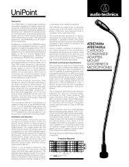
Description<br />
The AT853Rx is a wide-range miniature<br />
condenser microphone with a cardioid (unidirectional)<br />
polar pattern. It has been designed<br />
for use in high-quality sound reinforcement,<br />
professional recording, television and other<br />
demanding sound pickup applications. The<br />
AT853Rx is furnished with a vinyl-coated<br />
steel hanger that allows it to be positioned<br />
inconspicuously over a choir, orchestra, stage,<br />
etc., for very low-profile situations.<br />
Supplied as a cardioid, the AT853Rx easily<br />
accepts interchangeable elements to permit<br />
selection of angle of acceptance from 100° to<br />
360°. The following optional elements are<br />
available from an authorized Audio-<strong>Tech</strong>nica<br />
dealer or the A-T service department:<br />
AT853H-ELE hypercardioid, AT853O-ELE<br />
omnidirectional, AT853SC-ELE subcardioid.<br />
The AT853Rx features a 25' (7.6 m) permanently-attached<br />
miniature cable. Its free end<br />
connects to the provided AT8533x power<br />
module via internal solderless screw terminals<br />
for simple length adjustment in the field. It<br />
can be powered from any external 9V to 52V<br />
DC phantom power supply. A recessed<br />
switch in the power module permits choice<br />
of flat response, or a low-frequency roll-off to<br />
help control undesired ambient noise.<br />
The microphone element is enclosed in a<br />
rugged housing with a low-reflectance black<br />
finish. It is also available in white as the<br />
AT853RWx, with a white-finished microphone<br />
housing, windscreen, cable and steel hanger,<br />
for applications where the microphone must<br />
be hung against a light background.<br />
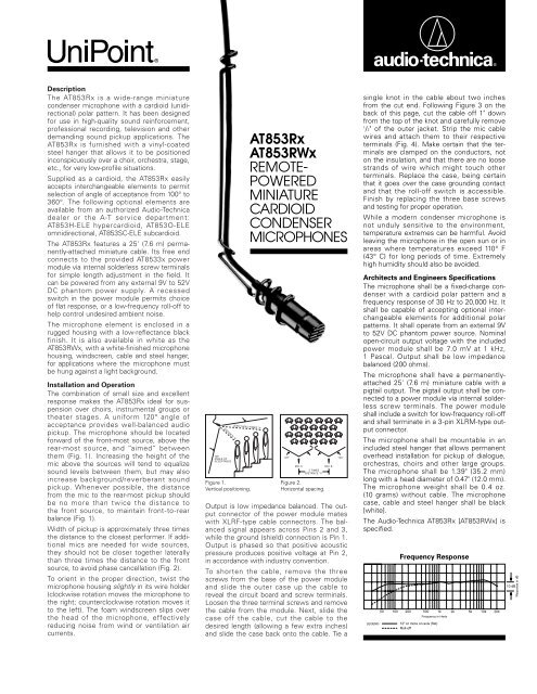
Installation and Operation<br />
The combination of small size and excellent<br />
response makes the AT853Rx ideal for suspension<br />
over choirs, instrumental groups or<br />
theater stages. A uniform 120° angle of<br />
acceptance provides well-balanced audio<br />
pickup. The microphone should be located<br />
forward of the front-most source, above the<br />
rear-most source, and “aimed” between<br />
them (Fig. 1). Increasing the height of the<br />
mic above the sources will tend to equalize<br />
sound levels between them, but may also<br />
increase background/reverberant sound<br />
pickup. Whenever possible, the distance<br />
from the mic to the rear-most pickup should<br />
be no more than twice the distance to<br />
the front source, to maintain front-to-rear<br />
balance (Fig. 1).<br />
Width of pickup is approximately three times<br />
the distance to the closest performer. If additional<br />
mics are needed for wide sources,<br />
they should not be closer together laterally<br />
than three times the distance to the front<br />
source, to avoid phase cancellation (Fig. 2).<br />
To orient in the proper direction, twist the<br />
microphone housing slightly in its wire holder<br />
(clockwise rotation moves the microphone to<br />
the right; counterclockwise rotation moves it<br />
to the left). The foam windscreen slips over<br />
the head of the microphone, effectively<br />
reducing noise from wind or ventilation air<br />
currents.<br />
DISTANCE “X”<br />
120°<br />
ANGLE OF<br />
ACCEPTANCE<br />
LESS THAN 2 TIMES “X”<br />
Figure 1.<br />
Vertical positioning.<br />
AT853Rx<br />
AT853RWx<br />
REMOTE-<br />
POWERED<br />
MINIATURE<br />
CARDIOID<br />
CONDENSER<br />
MICROPHONES<br />
Output is low impedance balanced. The output<br />
connector of the power module mates<br />
with XLRF-type cable connectors. The balanced<br />
signal appears across Pins 2 and 3,<br />
while the ground (shield) connection is Pin 1.<br />
Output is phased so that positive acoustic<br />
pressure produces positive voltage at Pin 2,<br />
in accordance with industry convention.<br />
To shorten the cable, remove the three<br />
screws from the base of the power module<br />
and slide the outer case up the cable to<br />
reveal the circuit board and screw terminals.<br />
Loosen the three terminal screws and remove<br />
the cable from the module. Next, slide the<br />
case off the cable, cut the cable to the<br />
desired length (allowing a few extra inches)<br />
and slide the case back onto the cable. Tie a<br />
120°<br />
MIC A<br />
MIC B<br />
3 TIMES<br />
DISTANCE “X”<br />
Figure 2.<br />
Horizontal spacing.<br />
120°<br />
single knot in the cable about two inches<br />
from the cut end. Following Figure 3 on the<br />
back of this page, cut the cable off 1" down<br />
from the top of the knot and carefully remove<br />
1<br />
/2" of the outer jacket. Strip the mic cable<br />
wires and attach them to their respective<br />
terminals (Fig. 4). Make certain that the terminals<br />
are clamped on the conductors, not<br />
on the insulation, and that there are no loose<br />
strands of wire which might touch other<br />
terminals. Replace the case, being certain<br />
that it goes over the case grounding contact<br />
and that the roll-off switch is accessible.<br />
Finish by replacing the three base screws<br />
and testing for proper operation.<br />
While a modern condenser microphone is<br />
not unduly sensitive to the environment,<br />
temperature extremes can be harmful. Avoid<br />
leaving the microphone in the open sun or in<br />
areas where temperatures exceed 110° F<br />
(43° C) for long periods of time. Extremely<br />
high humidity should also be avoided.<br />
Architects and Engineers Specifications<br />
The microphone shall be a fixed-charge condenser<br />
with a cardioid polar pattern and a<br />
frequency response of 30 Hz to 20,000 Hz. It<br />
shall be capable of accepting optional interchangeable<br />
elements for additional polar<br />
patterns. It shall operate from an external 9V<br />
to 52V DC phantom power source. Nominal<br />
open-circuit output voltage with the included<br />
power module shall be 7.0 mV at 1 kHz,<br />
1 Pascal. Output shall be low impedance<br />
balanced (200 ohms).<br />
The microphone shall have a permanentlyattached<br />
25' (7.6 m) miniature cable with a<br />
pigtail output. The pigtail output shall be connected<br />
to a power module via internal solderless<br />
screw terminals. The power module<br />
shall include a switch for low-frequency roll-off<br />
and shall terminate in a 3-pin XLRM-type output<br />
connector.<br />
The microphone shall be mountable in an<br />
included steel hanger that allows permanent<br />
overhead installation for pickup of dialogue,<br />
orchestras, choirs and other large groups.<br />
The microphone shall be 1.39" (35.2 mm)<br />
long with a head diameter of 0.47" (12.0 mm).<br />
The microphone weight shall be 0.4 oz.<br />
(10 grams) without cable. The microphone<br />
case, cable and steel hanger shall be black<br />
[white].<br />
The Audio-<strong>Tech</strong>nica AT853Rx [AT853RWx] is<br />
specified.<br />
LEGEND<br />
50<br />
100<br />
Frequency Response<br />
200<br />
500<br />
Frequency in Hertz<br />
12" or more on axis (flat)<br />
Roll-off<br />
1k<br />
2k<br />
5k<br />
10k<br />
20k<br />
10 dB<br />
Response in dB
AT853Rx<br />
AT853RWx<br />
270<br />
300<br />
240<br />
LEGEND<br />
200 Hz<br />
1 kHz<br />
5 kHz<br />
8 kHz<br />
0.47"<br />
12.0 mm<br />
330<br />
210<br />
Polar Pattern<br />
SCALE IS 5 DECIBELS PER DIVISION<br />
0<br />
180<br />
Dimensions<br />
30<br />
150<br />
60<br />
120<br />
90<br />
AT853Rx/AT853RWx SPECIFICATIONS †<br />
Figure 3 Figure 4<br />
ELEMENT<br />
Fixed-charge back plate<br />
permanently polarized condenser<br />
POLAR PATTERN<br />
Cardioid (Unidirectional)<br />
FREQUENCY RESPONSE<br />
30-20,000 Hz<br />
LOW-FREQUENCY ROLL-OFF<br />
150 Hz, 6 dB/octave<br />
OPEN CIRCUIT SENSITIVITY<br />
–43 dB (7.0 mV) re 1V at 1 Pa*<br />
IMPEDANCE<br />
200 ohms (1000 ohms without power module)<br />
MAXIMUM INPUT SOUND LEVEL<br />
138 dB SPL, 1 kHz at 1% T.H.D.<br />
DYNAMIC RANGE (TYPICAL)<br />
111 dB, 1 kHz at Max SPL<br />
SIGNAL-TO-NOISE RATIO 1<br />
67 dB, 1 kHz at 1 Pa*<br />
SWITCH<br />
Flat response, low-roll-off (recessed)<br />
PHANTOM POWER REQUIREMENTS<br />
9-52V DC, 2 mA typical<br />
WEIGHT<br />
MICROPHONE<br />
0.4 oz (10 grams)<br />
POWER MODULE<br />
2.1 oz (60 grams)<br />
DIMENSIONS<br />
MICROPHONE<br />
1.39" (35.2 mm) long, 0.47" (12.0 mm) head dia.<br />
POWER MODULE<br />
3.58" (91.0 mm) long, 0.83" (21.0 mm) diameter<br />
OUTPUT CONNECTOR (POWER MODULE) Integral 3-pin XLRM-type<br />
CABLE<br />
25' (7.6 m) long (permanently attached to<br />
microphone), 0.13" (3.2 mm) diameter,<br />
2-conductor, shielded cable<br />
ACCESSORIES FURNISHED (AT853Rx) AT8102 two-stage foam windscreen;<br />
AT8451 steel hanger<br />
(AT853RWx) AT8102WH foam windscreen;<br />
AT8451WH steel hanger<br />
(BOTH) AT8533x power module<br />
OPTIONAL INTERCHANGEABLE ELEMENTS AT853H-ELE hypercardioid (100°)<br />
AT853O-ELE omnidirectional (360°)<br />
AT853SC-ELE subcardioid (170°)<br />
† In the interest of standards development, A.T.U.S. offers<br />
full details on its test methods to other industry<br />
professionals on request.<br />
* 1 Pascal = 10 dynes/cm 2 = 10 microbars = 94 dB SPL<br />
1 Typical, A-weighted, using Audio Precision System One.<br />
25<br />
3.58"<br />
7.6 m 91.0 mm<br />
1.39"<br />
0.13"<br />
35.2 mm 3.2 mm<br />
Terminal<br />
screws<br />
0.83"<br />
21.0 mm<br />
Optional Accessories:<br />
• CP8201 line matching transformer<br />
(Lo-Z to 50,000 ohms).<br />
• AT8202 adjustable in-line attenuator for use<br />
with balanced Lo-Z microphones.<br />
• AT8314 2-conductor, shielded, vinyl-jacketed,<br />
broadcast-type cable with XLRF-type connector<br />
at microphone end, XLRM-type connector at<br />
equipment end. Available in 10', 20', 25', 30',<br />
50' & 100' lengths.<br />
• CP8506 four-channel 48V phantom power<br />
supply (AC powered).<br />
• AT8801 single-channel 48V phantom power<br />
supply (AC powered).<br />
1"<br />
1<br />
/2"<br />
Shield strands,<br />
fully twisted<br />
Yellow-Yellow<br />
Red-Red<br />
1<br />
/8" strip reds<br />
and yellows<br />
Case<br />
grounding<br />
contact<br />
Shield<br />
Audio-<strong>Tech</strong>nica U.S., Inc., 1221 Commerce Drive, Stow, Ohio 44224<br />
Audio-<strong>Tech</strong>nica Limited, Old Lane, Leeds LS11 8AG England<br />
Form No. 0310-0853-02-B/W P50875-01 © 1998 Audio-<strong>Tech</strong>nica U.S., Inc. Printed in U.S.A.<br />
S Y R<br />
PC board<br />
switch side<br />
Yellow-Yellow<br />
Red-Red<br />
One-Year Limited Warranty<br />
Audio-<strong>Tech</strong>nica microphones and accessories purchased<br />
in the U.S.A. are warranted for one year from<br />
date of purchase by Audio-<strong>Tech</strong>nica U.S., Inc. (A.T.U.S.)<br />
to be free of defects in materials and workmanship. In<br />
event of such defect, product will be repaired promptly<br />
without charge or, at our option, replaced with a new<br />
product of equal or superior value if delivered to<br />
A.T.U.S. or an Authorized Service Center, prepaid,<br />
together with the sales slip or other proof of purchase<br />
date. Prior approval from A.T.U.S. is required for<br />
return. This warranty excludes defects due to normal<br />
wear, abuse, shipping damage, or failure to use product<br />
in accordance with instructions. This warranty is void in<br />
the event of unauthorized repair or modification.<br />
For return approval and shipping information, contact<br />
the Service Department, Audio-<strong>Tech</strong>nica U.S., Inc.,<br />
1221 Commerce Drive, Stow, Ohio 44224.<br />
Except to the extent precluded by applicable state law,<br />
A.T.U.S. will have no liability for any consequential,<br />
incidental, or special damages; any warranty of<br />
merchantability or fitness for particular purpose<br />
expires when this warranty expires.<br />
This warranty gives you specific legal rights, and you<br />
may have other rights which vary from state to state.<br />
Outside the U.S.A., please contact your local dealer<br />
for warranty details.