4000 & 5000 Series Owners Manual - Audio-Technica
4000 & 5000 Series Owners Manual - Audio-Technica
4000 & 5000 Series Owners Manual - Audio-Technica

Create successful ePaper yourself
Turn your PDF publications into a flip-book with our unique Google optimized e-Paper software.
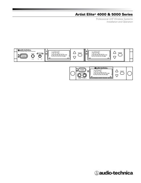
Artist Elite ® <strong>4000</strong> & <strong>5000</strong> <strong>Series</strong> Professional UHF Wireless SystemsThis device complies with the European R&TTE directive 1999/05/EC.Operation is subject to the condition that this device does not causeharmful interference.Dispose of exhausted batteries in accordance with local/nationalregulations. Do not dispose of exhausted batteries in a fire orincinerate.Remove outer cover in order to access power rating and modelnumber information. (handheld transmitter)Do not use the body-pack if antenna shows any signs of damage.(body-pack transmitter)CAUTION! The circuits inside the receiver and transmitter have beenprecisely adjusted for optimum performance. Do not attempt to openthe receiver or transmitter. To do so will void the warranty, and maycause improper operation.CAUTION: RISK OF ELECTRIC SHOCK DO NOT OPENTo prevent electric shock, do not remove the cover.There are no user-serviceable parts inside. Internaladjustments are for qualified professionals only. Refer allservicing to qualified service personnel.AVIS : RISQUE DE CHOC ÉLECTRIQUE NE PASOUVRIRPour prévenir un choc électrique, ne pas ouvrir lecouvercle. Il n’y aucune pièces de rechanges à l’intérieur.Tout ajustement interne doit être fait par une personnequalifié seulement. Référez tout réparation au personnelqualifié.Warning: This apparatus must be grounded.This product is a safety class 1 product. There must be anuninterruptible safety earth ground from the main power source tothe product’s AC input. Whenever it is likely that the protection hasbeen impaired, disconnect the power cord until the ground has beenrestored.Attention: Cet appareil doit être mise à la terre.Cet appareil est de classe de sûreté 1. Il doit y avoir unininterrompable de mise à la terre de sécurité provenant de la sourceprincipale de courant de l’appareil de l’entrée du courant alternatif.Quand la protection a été affaiblie, débrancher le fil de courant jusqu’àla mise à terre a bien été réétablie.Warning:This apparatus shall not be exposed to dripping or splashing.No objects filled with liquids, such as vases, shall be placed onthis apparatus.Do not install this apparatus in a confined space such as a bookcase orsimilar unit.The apparatus should be placed close enough to the AC outlet so thatyou can easily grasp the power cord at any time.CAUTION! Do not expose batteries to excessive heat, such as directsunlight or open fires.Warning: To prevent fire or shock hazard, do notexpose this appliance to rain or moisture.Attention: Pour prévenir feu ou choc électrique, nepas exposé l’appareil à la pluie ou à l’humidité.CAUTION: For continued protection against fire hazard, replace onlywith same type/rating of fuse.AVIS: Pour poursuivre la protection contre le feu, replacez la fusiblede même type/cote.WARNING: There are some sharp edges inside. To reduce the risk ofinjury, do not remove cover.ATTENTION: Bord tranchant à l’intérieur. Pour réduire le risque deblessure, ne pas ouvir le couvercle.Notice to individuals with implanted cardiac pacemakers or AICDdevices:Any source of RF (radio frequency) energy may interfere with normalfunctioning of the implanted device. All wireless microphones havelow-power transmitters (less than 0.05 watts output) which areunlikely to cause difficulty, especially if they are at least a few inchesaway. However, since a “body-pack” mic transmitter typically isplaced against the body, we suggest attaching it at the belt, rather thanin a shirt pocket where it may be immediately adjacent to the medicaldevice. Note also that any medical-device disruption will cease whenthe RF transmitting source is turned off. Please contact your physicianor medical-device provider if you have any questions, or experience anyproblems with the use of this or any other RF equipment.The systems can be supplied in five frequency bands within theUHF range. Please note: Frequency usage is different for eachcountry. Your <strong>Audio</strong>-<strong>Technica</strong> agent will have all the necessary detailson the available legal frequencies for your area.Band C: 541.500 – 566.375 MHzBand D: 655.500 – 680.375 MHzBand E: 795.500 – 820.000 MHzBand F: 840.125 – 864.875 MHzBand G: 721.500 – 746.375 MHzFor use in China, it is necessary for the user to utilize a CCC certifiedpower cord.This device complies with part 15 of the FCC Rules. Operation issubject to the condition that this device does not cause harmfulinterference.This device complies with INDUSTRY CANADA R.S.S. 210, enconformité avec IC: RSS-210/CNR210. Operation is subject tothe following conditions: 1) This device may not cause harmfulinterference and 2) this device must accept any interference received,including interference which may cause undesired operation.CAUTION! The circuits inside the receiver and transmitter have beenprecisely adjusted for optimum performance and compliance withfederal regulations. Do not attempt to open the receiver or transmitter.To do so will void the warranty, and may cause improper operation.Attention! Ne pas exposer les piles à une chaleur excessive, telleque la lumière directe du soleil ou le feu.
6Artist Elite ® <strong>4000</strong> & <strong>5000</strong> <strong>Series</strong> Professional UHF Wireless SystemsIntroductionThank you for choosing an <strong>Audio</strong>-<strong>Technica</strong> professional wirelesssystem. You have joined thousands of other satisfied customers whohave chosen our products because of their quality, performance andreliability. This <strong>Audio</strong>-<strong>Technica</strong> wireless microphone system is thesuccessful result of years of design and manufacturing experience.Recent advances in the quality and sophistication of professionallive-sound systems have been nothing short of revolutionary. Tours,clubs, broadcast events, corporate facilities and worship venuessound better than ever, utilizing better system design and bettercomponents in the audio chain.That’s why <strong>Audio</strong>-<strong>Technica</strong> has been partnering with industryprofessionals on the front line of this revolution — the top touringcompanies, award show designers, FOH and monitor engineers,audio consultants and artists — to learn what it takes to make thebest-sounding, most reliable and consistent microphones for the livesoundindustry.We listened carefully. Then, we applied this knowledge to thecreation of the Artist Elite ® line of high-performance microphonesand wireless systems. Our ultimate design goal was this: Eachmodel must extend the performance of a sound system, not limit it.Artist Elite SystemsArtist Elite <strong>4000</strong> <strong>Series</strong> and <strong>5000</strong> <strong>Series</strong> wireless systems by<strong>Audio</strong>-<strong>Technica</strong> share a range of transmitters in common, bothbody-pack and handheld types. The difference between the twoseries is simply in the choice of receiver:<strong>4000</strong> <strong>Series</strong> AEW-R4100 half-rack single receiver with multi-unit,multi-channel control linking.<strong>5000</strong> <strong>Series</strong> AEW-R5200 full-rack independent dual receiverwith multi-unit, multi-channel control linking, plusEthernet computer-control connection, and softwarefor graphical user interface. In addition a “passthrough”AC outlet on each receiver with includedAC jumper cable permits daisy-chaining of an entireAEW-R5200 receiver stack, freeing AC outlets forother equipment.Both Artist Elite receiver models feature True Diversity reception.Two antennas feed two completely independent RF sections on thesame frequency; automatic logic circuitry continuously compares andselects the superior received signal, providing better sound quality andreducing the possibility of interference and dropouts. Both receiversoffer a choice of up to 996 operating frequencies in a 25 MHz-wideUHF frequency range. 25 kHz frequency spacing enables the systemsto easily find an open frequency in crowded RF environments.Transmitter models in the Artist Elite <strong>Series</strong> include:A UniPak ® body-pack transmitter:• AEW-T1000a UniPak body-pack transmitterFour handheld mic/transmitters with different Artist Elite microphonecapsules:• AEW-T3300a Handheld mic/transmitter with AEW-C3300cardioid condenser capsule• AEW-T4100a Handheld mic/transmitter with AEW-C4100cardioid dynamic capsule• AEW-T5400a Handheld mic/transmitter with AEW-C5400cardioid condenser capsule• AEW-T6100a Handheld mic/transmitter with AEW-C6100hypercardioid dynamic capsuleAll components in the <strong>4000</strong>/<strong>5000</strong> <strong>Series</strong> may be used together ina variety of unit combinations and system configurations to createextremely flexible and powerful solutions for a variety of applications.<strong>4000</strong>/<strong>5000</strong> <strong>Series</strong> systems and components operate on up to996 frequencies in six UHF frequency bands to provide flexibleperformance in a wide variety of regions worldwide:Frequency RangeNum. of FreqBand C: 541.500 to 566.375 MHz 996Band D: 655.500 to 680.375 MHz 996Band E: 795.500 to 820.000 MHz 981Band F: 840.125 to 864.900 MHz 953Band G: 721.500 to 746.375 MHz 996For simplicity, model numbers used throughout this manual willreference only the basic model number without the band indications.The IntelliScan automatic channel assignment system, providedon both the <strong>4000</strong> and <strong>5000</strong> <strong>Series</strong> receivers, greatly simplifies theselection of usable frequencies in both single-channel and multichannelwireless systems. The receivers are first linked togetherwith included communication cables. The selected “Master” receiverthen “knows” how many total channels it is looking for. It can scanthe available frequencies, checking for local interference sources,selecting a group of channels that will all work together (using abuilt-in frequency plan), and automatically setting the other receiversaccordingly. Once this procedure is completed, it’s just a matter ofsetting the transmitter frequencies to match those of the receivers.Artist Elite ® <strong>Series</strong> components feature an advanced digitalTone Lock squelch system and unique Dual Compander design(patents pending). As a result, Artist Elite <strong>Series</strong> transmitters andreceivers must be used together in Tx-Rx pairs and should notbe mixed with components from other <strong>Audio</strong>-<strong>Technica</strong> wirelesssystems, or with those of other manufacturers.All Artist Elite <strong>Series</strong> components feature soft-touch controls forquick, easy access to a formidable range of functions; a backlit LCDinformation display in each unit provides convenient visual indicationof unit settings and operation. Digital data sent by the transmitters isavailable for display on the receivers.Multi-channel SystemsArtist Elite ® systems provide extensive monitoring and controlfacilities. Transmitter data, in addition to being available at thetransmitter, is conveyed in digital form to and displayed on theassociated receiver.
7Artist Elite ® <strong>4000</strong> & <strong>5000</strong> <strong>Series</strong> Professional UHF Wireless SystemsLinked systems: Both Artist Elite receivers provide linking jacks andcables. AEW-R4100 and AEW-R5200 receivers may be combined inlinked multi-channel systems, if desired.Ethernet-based monitoring and control (AEW-R5200): Somewireless systems on the market offer remote control/monitoring ofthe receiver via a serial interface, but the <strong>Audio</strong>-<strong>Technica</strong> AEW-R5200receiver takes this a significant step further by including controlover IP using standard networking protocol and Ethernet interfacing.This permits receivers in a system to be integrated, monitored andcontrolled from a single computer in real-time. And not only canan individual channel of an individual receiver be examined and itssettings modified: if the transmitter on that channel is activated,thanks to the digital data link, data from the associated transmittercan also be monitored.Because standard control over IP is used, Ethernet-connected AEWsystems can range from a single laptop controlling a free-standingmulti-channel system, to local area network-based systems, tosystems controlled via the Internet, even from great distances.Complete setup and operating information for computer-connectedAEW systems will be found in the separate Computer Interfacemanual provided with AEW-R5200 receivers and <strong>5000</strong> <strong>Series</strong> systems.TransmittersThe versatile AEW-T1000a UniPak ® body-pack transmitter featuresa metal case and includes field-replaceable helical and flexiblewireantennas. It has both low- and high-impedance inputs plusa bias connection, for use with dynamic and electret condensermicrophones, as well as Hi-Z instrument pickups. In addition to itsprogrammable functions, the transmitter includes a three-positionsliding control cover to limit access, if desired, to only the Power/Mute button, or to no controls at all, as appropriate for the applicationand/or user.The handheld microphone/transmitters feature metal-bodyconstruction. Four models are available, incorporating a variety ofcapsules from the Artist Elite wired-microphone series created forprofessional live-sound venues.All Artist Elite <strong>Series</strong> transmitters use two 1.5V AA batteries foreconomical operation and wide availability. The receiver and bothtransmitters have “fuel gauge” battery condition indicators with lowbatterywarnings.Please note that in multiple-system applications there must be atransmitter-receiver combination set to a separate frequency for eachinput desired (only one transmitter for each receiver). Because thewireless frequencies are within UHF TV frequency bands, only certainoperating frequencies may be usable in a particular geographic area.Also, only certain of the available operating frequencies may be usedtogether. Operating frequencies and IntelliScan frequency groupingswill be found on page 25. (Use of the IntelliScan channel assignmentsystem will determine and set appropriate frequencies automatically.)Receiver InstallationLocationFor best operation the receiver should be at least 1 m (3 ft.) abovethe ground and at least 1 m (3 ft.) away from a wall or metal surfaceto minimize reflections. The transmitter should be at least 1 m (3 ft.)from the receiver, as shown in Figure A. Keep antennas away fromnoise sources such as digital equipment, motors, automobiles andneon lights, as well as away from large metal objects.Fig. AOutput ConnectionsThere are two audio outputs on the back panel: an XLR Mic Outputand a 1 /4" (6.3 mm) phone jack Instrument Output. The two isolatedaudio outputs permit simultaneous feeds to two different inputs.AEW-R4100: This receiver offers a balanced XLR Mic jack and anunbalanced Instrument 1 /4" TS phone jack. Output levels of both areadjusted by the rear-panel Attenuator (ATTN) switch.AEW-R5200: Since there are two independent channels of receiverin the AEW-R5200, there are two sets of output jacks. All audiooutputs on the AEW-R5200 are transformer-isolated and balanced.The ground connections of both outputs on each receiver channelmay be interrupted (“lifted”) by use of their associated Ground Liftswitch. This permits feeding mixers with different ground levelswithout an additional external splitter. The Instrument output is abalanced 1 /4" TRS jack with “audio +” on the Tip, “audio –” on theRing and ground (shield) on the Sleeve. The rear-panel Attenuator(ATTN) switch for each receiver channel adjusts levels of bothoutputs in its channel. Use the appropriate shielded audio cable forconnections between the receiver and the input(s) of the mixer orother equipment.AntennasAttach a pair of UHF antennas to the antenna input jacks. Theantennas are normally positioned in the shape of a “V” (both45° from vertical) for best reception. In addition to rotating at theconnector, the included half-wave antennas pivot from straight toright-angle.Antennas can be remotely located from the receiver. However, dueto signal loss in cables at UHF frequencies, use the lowest-loss RFcables practical for any cable runs over 25 feet. RG8-type is a goodchoice. Use only copper-shielded cable, not CATV-type foil-shieldedwire. <strong>Audio</strong>-<strong>Technica</strong> offers auxiliary antennas and quality RF cablesin four lengths.Antenna PowerThe antenna input jacks also can provide +12V DC output on theircenter pins to power inline RF devices. A maximum of 20 mA can bedrawn from each of the jacks. While an accidental short-circuit will
UHF SYNTHESIZED DIVERSITY RECEIVER AEW-R5200ONOFFOUTPUTPHONESUHF SYNTHESIZED DIVERSITY RECEIVER AEW-R5200ONOFFOUTPUTPHONESUHF SYNTHESIZED DIVERSITY RECEIVER AEW-R5200ONOFFONOFFONOFFPHONESPHONESMIN–LEVEL–MAXMIN–LEVEL–MAXOUTPUTALERTALERTPHONESMINMINMINPUSH SELLEVELPUSH SELLEVELPUSH SELLEVELMAXMAXMAXRX NAMEUHF SYNTHESIZED DIVERSITY RECEIVER AEW-R4100RX NAMEUHF SYNTHESIZED DIVERSITY RECEIVER AEW-R4100RX NAMERX NAMERX NAMEMODE/SETMODE/SETMODE/SETMODE/SETMODE/SETRX NAMERX NAMERX NAMEMODE/SETMODE/SETMODE/SET8Artist Elite ® <strong>4000</strong> & <strong>5000</strong> <strong>Series</strong> Professional UHF Wireless Systemsnot harm the internal 12V supply, make certain that an antenna cableshield does not contact the center conductor. Antenna Power (“ANT.PWR”) is selected (switched on or off) from the LCD menu. (On theAEW-R5200, Antenna Power will be found in the menu on Channel1 only.)Front-mount AntennasAEW-R4100: Provision has been made to move the antenna jacksfrom the rear to the front of the receiver. However, because thisinvolves opening the receiver case and exposing AC power circuitry,instructions are not included in this manual. A qualified servicetechnician must perform this modification.AEW-R5200: BNC-to-BNC connectors and jumper cables are includedwith the unit to permit mounting antennas on the front panel.• BNC-BNC through-panel connectors: Remove the nut andlock-washer from each connector. Install the connectors fromthe front into the two panel holes. Note that the flat on thethreaded section must be aligned with the flat in each panelhole. Secure each connector from the back with its lockwasherand nut, tightening the nut firmly.• BNC-BNC cable jumpers: Connect the jumpers to the rearantenna jacks first; then attach them to the BNC connectors onthe front panel. Make certain the bayonet twist-rings are fullylatched on the connectors at both ends.AEW-R5200: Press and release the Phones Level control knob toswitch headphone monitoring from Channel 1 to Channel 2 andback again. Small, lighted indicators just above the knob show whichreceiver channel is being monitored.Power ConnectionsThe switching power supply is designed to operate properly fromany AC power source 100–240V, 50/60 Hz without user adjustment.Simply connect the receiver to a standard AC power outlet, usingonly an IEC-type input cordset approved for the country of use.Power to the unit is controlled by the front-panel Power switch.AEW-R5200: An auxiliary AC “jumper” (pass-through) outlet isprovided on the rear panel, and a ”jumper” power cordset is included,to simplify power connections by “daisy-chaining” an array of AEW-R5200’s. Maximum output from the auxiliary outlet is 5 Amperes,which will easily handle a full complement of AEW-R5200 units.“Link” ConnectionsArtist Elite <strong>Series</strong> multi-channel systems can comprise all AEW-R4100,all AEW-R5200, or combinations of AEW-R4100 and AEW-R5200receivers. The exclusive IntelliScan channel assignment systemprovides easy, automatic scanning of the RF spectrum and assignmentof usable, compatible frequencies to all linked AEW receiver channels.Both AEW receiver models can be interconnected using Link In/Outjacks and included link cables. In addition, the AEW-R5200 offers abuilt-in Ethernet 10 BaseT connection, with interface software providedon CD-ROM. See the separate AEW Control Interface manual providedwith AEW-R5200 receivers and <strong>5000</strong> <strong>Series</strong> systems.All AEW receivers in a linked multi-channel system should beinterconnected with included link cables. When the system isproperly configured, the “slave” units will “link data in” to the“Master” unit. (See Figure B for an example.)1. First, decide which receiver will be the “Master” unit. Connecta link cable to the Link In jack only. (In an AEW-R5200, theChannel 1 unit is the Master and Channel 2 becomes the first“slave.”)2. Connect the free end of the link cable from the Master unit (in#1 above) to the Link Out jack of the desired “next” unit.3. Connect one end of a new link cable to the Link In jack of theunit in #2 above.4. Connect the free end of the link cable from the unit in #2above to the Link Out jack of the desired “next” unit.5. Continue this process of “daisy-chaining” the system’sreceivers together with link cables. The “last” unit in thesystem will have a cable connected to its Link Out jack, but noconnection to its Link In jack.Installing link cables starting with the last slave unit and workingtoward the Master unit is also acceptable practice.The attachment order of link cables establishes the numerical orderof the receivers in the multi-channel system, from the selectedMaster unit through all the slave units. (In the case of AEW-R5200receivers, a unit’s Channel 1 always comes before its Channel 2.)In a multi-channel system that includes both models of receivers,it’s common practice to position all the AEW-R5200 units first in thechain; followed by any AEW-R4100 units.Note 1: For the receiver linking to work, all receivers in the systemmust have AC power applied at the same time, or the Masterreceiver must be turned on last.Note 2: In addition, if AC power is interrupted or a link connectionis broken at any receiver in a linked system, even for an instant,receivers from that unit onward are no longer linked to the system.When all power and linking have been restored, the system mustbe restarted by turning all the receivers Off, then On (all turned onsimultaneously, or the Master receiver must be turned on last). Thiswill re-initialize the system and re-establish all the data links.Fig. BAEW-R5200AEW-R5200AEW-R5200AEW-R4100POWERPOWERPOWERPOWERSLV 6MASTER SLV 1SLV 2 SLV 3SLV 4 SLV 5LINKSOUT (N/A)INOUTINOUTINOUTINPOWEROUTOUT (N/A)AEW-R4100 SLV 7
9Artist Elite ® <strong>4000</strong> & <strong>5000</strong> <strong>Series</strong> Professional UHF Wireless SystemsEthernet connections (AEW-R5200):An RJ-45 jack on the rear panel of each AEW-R5200 provides anEthernet 10 BaseT data/control connection from both of its channelsto an external computer system. Data monitored includes actual, realtime“RF” and “AF” levels for receiver channels with direct Ethernetconnections to the associated computer. All other linked receivers ina system supply control-function access and all their data – exceptfor “RF” and “AF” levels – to the computer connected to the Masterreceiver.Other than being able to “see” the “RF” and “AF” levels, allfunctions of all receivers in a linked system can be monitored andcontrolled from the computer connected to the Master receiver.Details of the computer setup and operation will be found in aseparate AEW Control Interface manual provided with AEW-R5200receivers and <strong>5000</strong> <strong>Series</strong> systems.Multiple AEW-R5200 receivers in a system can each provide realtime“RF” and “AF” levels to the associated computer if eachAEW-R5200 has its own Ethernet connection, through an Ethernethub, to the computer.Receiver Controls and FunctionsFig. C AEW-R5200 Receiver Front PanelUHF SYNTHESIZED DIVERSITY RECEIVER AEW-R5200OUTPUTPUSH SELLEVELMODE/SETMODE/SETONPOWERRX NAMERX NAMEOFFPHONESMINMAX13 1 2 3 4 5 6 7 8 9 10 11 12 13ININSTRUMENTMIC OUTPUTFront Panel Controls and Functions (Fig. C)NETWORKANT. BINTERFACEANT. A1 POWER SWITCH: Press the power ATTN (dB) switch to turn the receiverEXTERNAL OUTPUTGROUND GROUNDMUTE(BAL)LIFTon. After a short power-up sequence, the display shows theoperating frequency and the alert light is illuminated (if no activetransmitters are present on this frequency). The receiver may alsodisplay a system position (i.e., “MASTER”, “SLV-#”) or anassigned transmitter or receiver name (if this feature has beenset up—the display recalls the setting from the last time powerwas applied). Refer to page 13 on setting up receiver names orpage 18 on setting up transmitter names.2 HEADPHONE OUTPUT: 1 /4" (6.3 mm) TRS (“stereo”) phone jackprovides monitoring of the receiver’s output. Plug in either amono or "stereo" headphone to monitor receiver signal.Note: On an operating unit, be careful not to press the Powerswitch accidentally when inserting a headphone jack or adjustingthe headphone level. In addition to interrupting receiver operation,even a momentary loss of power to a single unit within a linkedmulti-channel system will cause the loss of linking connection to theaffected receiver and all those “downstream” from it.3 HEADPHONE LEVEL CONTROL / CHANNEL SWITCH: Thiscontrol is used to set a comfortable listening level for theheadphone jack; it does not affect receiver audio output. Turn thecontrol clockwise to increase the level. Press-and-release the knobto switch between Channel 1 and Channel 2.0/-6/-12BALANCEDINEXTERNALMUTEMIC OUTPUT50/60HzChannel 1 / Channel 2OUTPUTLINK5A/500W MAX0/-6/-125 / 9 ALERT INDICATOR: The alert light illuminates WARNING: to indicate to theATTN (dB)THIS APPARATUSGROUND GROUNDOUTMUST BE EARTHED.user that something LIFT needs attention; for example, the transmitterbatteries are low, or the transmitter is muted or turned off.INSTRUMENTOUTPUT(BAL)BALANCEDINThe Alert Indicator lights:(a) When the receiver is in the Mute mode,(b) When no RF signal is received from the transmitter,(c) When only one or two RF signal-strength bars are on,(d) When the transmitter is in the Mute mode,(e) When audio modulation level from the transmitter is close tothe clipping point (AF +6 bar), or(f) When the “LOW BAT” warning appears in the LCD(transmitter battery is weak).6 / 10 LCD WINDOW: Liquid Crystal Display indicates control settingsand operational readings. It is also used in conjunction with theMode/Set and Up/Down arrow buttons to change user-configurablefunctions. See Figure G on page 12 for details.100V-240VAC˜7 / 11 UP/DOWN BUTTONS: Press Up or Down arrow button, inconjunction with the Mode/Set button, to scroll through thefunction menu in Menu mode or through the available choicesfor a given function in Edit mode. When the receiver is innormal operating mode, the Up/Down arrow buttons scrollthrough Receiver Address (“MASTER” or “SLV-#”), ReceiverPreset Name, or Transmitter Preset Name.4 HEADPHONE CHANNEL INDICATOR: Shows which receiverchannel is feeding the monitor headphones.
10Artist Elite ® <strong>4000</strong> & <strong>5000</strong> <strong>Series</strong> Professional UHF Wireless SystemsReceiver Controls and Functions (Continued)8 / 12 MODE/SET BUTTON: Use in conjunction with the Up/Downarrow buttons to step through menus, choose operatingfrequency and select receiver function options. The Mode/Set button has different functions depending on the status of thereceiver. Two distinct operations are associated with this button:Touch:A momentary press of the Mode/Set button. It is used toenter Menu mode, to enter Edit mode, or to Escapewithout making any changes to current settings.Hold:A press and hold (about two seconds) of the Mode/Setbutton. It is used to accept a new setting when thereceiver is in Edit mode or to save the current settings toone of the five user-defined name presets or the internalmemory location (“NAME?”).13 FRONT-MOUNT ANTENNAS: Cables and panel connectors areincluded with the AEW-R5200 to permit attaching antennas at thefront panel.UHF SYNTHESIZED DIVERSITY RECEIVER AEW-R5200OUTPUTPUSH SELLEVELMODE/SETMODE/SETONPOWERRX NAMERX NAMEOFFPHONESMINMAXFig. D AEW-R5200 Receiver Rear PanelININSTRUMENTBALANCEDMIC OUTPUTININSTRUMENTBALANCEDMIC OUTPUTIN100V-240VAC˜50/60HzOUTPUT5A/500W MAXANT. BEXTERNALMUTEOUTPUT(BAL)0/-6/-12ATTN (dB)GROUND GROUNDLIFTNETWORKINTERFACEANT. AEXTERNALMUTEOUTPUT(BAL)0/-6/-12ATTN (dB)GROUND GROUNDLIFTLINKOUTWARNING:THIS APPARATUSMUST BE EARTHED.31 14 15 16 17 18 19 20 21 22 23 24 25 26 27 28 29 3031Rear Panel Controls and Functions (Fig. D)14 ANTENNA INPUT JACK: BNC-type antenna connector for Tuner“B.” Attach the antenna directly, or extend it with a low-lossantenna cable. See the ”Antennas” section on page 7 for moredetails. Antenna power at +12 volts is available at both antennajacks; select it via the LCD menu on Channel 1.15 / 22 EXTERNAL MUTE: Permits manual and absolute muting ofthe receiver via a 1 /4" TS phone jack and a user-provided externalswitch. “Shorting” the jack (closing the switch connection) mutesthe receiver channel. When External Mute has been applied, theonly way to un-mute the receiver is to open the External Muteswitch connection.16 / 23 INSTRUMENT OUTPUT JACK: 1 /4" transformer-isolated TRSbalanced phone jack output. Tip: “audio +”; Ring: “audio –”;Sleeve: ground (shield). Can be connected to an aux-level inputof a mixer, guitar amp or tape recorder. Using the associatedGround Lift switch permits feeding equipment with differentground levels.17 / 24 AF OUTPUT ATTENUATOR: Three-position switch adjustsaudio output level of both audio output jacks, with attenuation of0 dB, –6 dB or –12 dB.18 / 25 MIC OUTPUT JACK: XLRM-type connector. Pin 1: ground(shield); Pin 2: “audio +”; Pin 3: “audio –”. A standard 2-conductorshielded cable can be used to connect the receiver output to abalanced microphone-level input on a mixer or integratedamplifier. This output is transformer-isolated from the 1 /4" TRSInstrument output jack.19 / 26 GROUND LIFT SWITCH: Disconnects the ground of both theMic and Instrument output jacks on the associated receiverchannel. Normally, the switch should be to the right (groundconnected). If hum caused by a ground loop occurs, slide switchto the left (ground lifted).20 NETWORK INTERFACE CONNECTOR: An Ethernet connectionon the AEW-R5200 provides full communication and monitor/control by an associated computer. See the separate AEW ControlInterface manual for computer setup and operation.21 ANTENNA INPUT JACK: Connector for Tuner “A.” Attach theantenna directly, or extend it with a low-loss antenna cable.Antenna power at +12 volts is available at both antenna jacks.27 LINK IN JACK: Connect the provided cable to this jack with theindex mark on the plug aligned toward the screw head to the rightof the jack. The receiver with a Link In and no Link Out connectionis the “Master” unit. (With an AEW-R5200 in the Master position,its Channel 1 is the system’s Master and its Channel 2 is the first“slave.”)28 LINK OUT JACK: Connect the provided cable to this jack with theindex mark on the plug aligned toward the screw head to the rightof the jack. The receiver with a Link Out and no Link In connectionis the last slave in a multi-unit system.29 AUXILIARY AC OUTLET: An auxiliary AC pass-through outlet andincluded “jumper” power cordset simplify making powerconnections to an array of AEW-R5200’s. Maximum output fromthe auxiliary AC outlet is 5 Amperes.30 AC POWER INPUT: IEC-type connector for 100V–240V AC,50/60 Hz power input. No adjustment for mains voltage/frequency is necessary.31 REAR RACK MOUNT: Mounts are provided at the rear of the sidepanels to permit attachment to rear rack rails in racks so equipped.The additional support is especially helpful when equipment istransported.
11Artist Elite ® <strong>4000</strong> & <strong>5000</strong> <strong>Series</strong> Professional UHF Wireless SystemsFig. E AEW-R4100 Receiver Front PanelONOFFPOWERALERTMODE/SETRX NAMEPHONESMIN–LEVEL–MAXUHF SYNTHESIZED DIVERSITY RECEIVER AEW-R410039 33 32 34 35 3637 3839Front Panel Controls and Functions (Fig. E)32 POWER SWITCH: Press the power switch to turn the receiveron. After a short power-up sequence, the display shows theoperating frequency and the alert light is illuminated (if no activetransmitters are present on this frequency). The receiver may alsodisplay a system position (i.e., “MASTER”, “SLV-#”) or anassigned transmitter or receiver name (if this feature has beenset up—the display recalls the setting from the last time powerwas applied). Refer to page 13 on setting up receiver names orpage 18 on setting up transmitter names.33 HEADPHONE OUTPUT: 1/4" (6.3 mm) TRS (“stereo”) phone jackprovides monitoring of the receiver’s output. Plug in either amono or "stereo" headphone to monitor receiver signal.Note: On an operating unit, be careful not to press the Powerswitch accidentally when inserting a headphone jack or adjustingthe headphone level. In addition to interrupting receiver operation,even a momentary loss of power to a single unit within a linkedmulti-channel system will cause the loss of linking connection to theaffected receiver and all those “downstream” from it.34 HEADPHONE LEVEL CONTROL: This control is used to set acomfortable listening level for the headphone jack; it does notaffect receiver audio output. Turn the control clockwise toincrease the level.35 ALERT INDICATOR: The alert light illuminates to indicate to theuser that something needs attention; for example, the transmitterbatteries are low, or the transmitter is muted or turned off.BALANCEDINMIC OUTPUTININSTRUMENT37 UP/DOWN BUTTONS: Press Up or Down arrow button, in0/-6/-12ANT. BANT. AAC˜ 100V-240VATTN (dB)50/60HzOUTPUTGROUND GROUND IN – LINK – OUT WARNING:(UNBAL.)LIFTTHIS APPARATUS MUST BE EARTHED.conjunction with the Mode/Set button, to scroll through thefunction menu in Menu mode or through the available choicesfor a given function in Edit mode. When the receiver is innormal operating mode, the Up/Down arrow buttons scrollthrough Receiver Address (“MASTER” or “SLV-#”), ReceiverPreset Name, or Transmitter Preset Name.38 MODE/SET BUTTON: Use in conjunction with the Up/Down arrowbuttons to step through menus, choose operating frequency andselect receiver function options. The Mode/Set button hasdifferent functions depending on the status of the receiver. Twodistinct operations are associated with this button:Touch:Hold:A momentary press of the Mode/Set button. It is used toenter Menu mode, to enter Edit mode, or to Escapewithout making any changes to current settings.A press and hold (about two seconds) of the Mode/Setbutton. It is used to accept a new setting when thereceiver is in Edit mode or to save the current settings toone of the five user-defined name presets or the internalmemory location (“NAME?”).39 MOUNTING ADAPTERS: For mounting the receiver in anystandard 19" rack. Attach to the receiver with the screwssupplied. (Use an optional AT8628a joining-plate kit to mount twoAEW-R4100 receivers side by side.)The Alert Indicator lights:(a) When the receiver is in the Mute mode,(b) When no RF signal is received from the transmitter,(c) When only one or two RF signal-strength bars are on,(d) When the transmitter is in the Mute mode,(e) When audio modulation level from the transmitter is close tothe clipping point (AF +6 bar), or(f) When the “LOW BAT” warning appears in the LCD(transmitter battery is weak).36 LCD WINDOW: Liquid Crystal Display indicates control settingsand operational readings. It is also used in conjunction with theMode/Set and Up/Down arrow buttons to change userconfigurablefunctions. See Figure G on page 12 for details.
12Artist Elite ® ONPOWER ALERT<strong>4000</strong> & <strong>5000</strong> <strong>Series</strong> Professional UHF Wireless MODE/SET SystemsOFFRX NAMEPHONESMIN–LEVEL–MAXUHF SYNTHESIZED DIVERSITY RECEIVER AEW-R4100Receiver Controls and Functions (Continued)Fig. F AEW-R4100 Receiver Rear PanelININSTRUMENTBALANCEDMIC OUTPUTINANT. BOUTPUT(UNBAL.)0/-6/-12ATTN (dB)GROUND GROUND IN – LINK – OUTLIFTANT. AAC˜ 100V-240V50/60HzWARNING:THIS APPARATUS MUST BE EARTHED.Rear Panel Controls and Functions (Fig. F)40 ANTENNA INPUT JACK: BNC-type antenna connector for Tuner“B.” Attach the antenna directly, or extend it with a low-lossantenna cable. See the “Antennas” section on page 7 for moredetails.41 INSTRUMENT OUTPUT JACK: 1 /4" phone jack. Can be connectedto an aux-level input of a mixer, guitar amp or tape recorder. Onthe AEW-R4100, this is an unbalanced TS phone jack.42 AF OUTPUT ATTENUATOR: Three-position switch adjusts audiooutput level of both audio output jacks with attenuation of 0 dB,–6 dB or –12 dB.43 MIC OUTPUT JACK: XLRM-type connector. A standard2-conductor shielded cable can be used to connect the receiveroutput to a balanced microphone-level input on a mixer orintegrated amplifier.44 GROUND LIFT SWITCH: Disconnects the ground pin of thebalanced output jack (43) from ground. Normally, the switchshould be to the right (ground connected). If hum caused by aground loop occurs, slide switch to the left (ground lifted).45 LINK IN JACK: Connect provided cable to this jack with the indexmark on the plug aligned toward the screw head above the jack.The receiver with a Link In and no Link Out connection is the“Master” unit.46 LINK OUT JACK: Connect provided cable to this jack with theindex mark on the plug aligned toward the screw head above thejack. The receiver with a Link Out and no Link In connection is thelast unit in a multi-unit system.47 ANTENNA INPUT JACK: Connector for Tuner “A.” Attach theantenna directly, or extend it with a low-loss antenna cable.48 AC POWER INPUT: IEC-type connector for 100V–240V AC,50/60 Hz power input. No adjustment for mains voltage/frequency is necessary.49 RF SIGNAL LEVEL INDICATOR: Shows the strength of the RFsignal received from the transmitter. Also indicates which Tuner(A or B) has the better reception and is in operation. When theMETER HOLD function is on, the lowest-level RF signal receivedfrom the transmitter is indicated by a flashing bar.50 ALPHANUMERIC DISPLAY: Shows Receiver Name (57),Transmitter Name (57), or Link Address (MASTER, or SLV and theslave number). The factory setting displays “DEF” in ReceiverName mode (“RX NAME”). Once the settings have beenchanged, the unit will display the last setting and mode selected.Also flashes the “LOW.BAT” warning when the associatedtransmitter’s batteries are weak.404142 43 44 45 46 47 48Fig. G Receiver LCD Window50 54 55 56TX LOTX HITX LOCKRX LOCKTX NAMERX NAME49 51 52 53 58 57 5951 TRANSMITTER BATTERY INDICATOR: Displays a maximum offour bar segments, with four bars indicating full power.52 FREQUENCY DISPLAY: Indicates the current frequency settingin MHz.53 “EDIT”: Appears and flashes when the receiver is in edit mode.54 TRANSMITTER RF POWER DISPLAY: Indicates either “TX LO”or “TX HI”.55 “TX LOCK”: Appears when the transmitter is in one of its threelock settings (ALL.LOC, MUT.LOC or PWR.LOC).56 “RX LOCK”: Appears when the receiver is in one of its three locksettings (ALL.LOC, PC.LOC or RX.LOC).57 TX/RX NAME: Indicates whether the transmitter name or thereceiver name is displaying in the top line of the LCD display.58 “MUTE”: Appears when the receiver or transmitter is muted,when the receiver is not receiving an audio signal, or when thereceiver is externally muted by use of the EXTERNAL MUTE jack.59 AF LEVEL INDICATOR: Shows the audio modulation level ofthe received signal. When the METER HOLD function is on, thebar corresponding to the highest level reached will stay lit.
13Artist Elite ® <strong>4000</strong> & <strong>5000</strong> <strong>Series</strong> Professional UHF Wireless SystemsChanging receiver settingsTouch:Hold:A momentary press of the Mode/Set button. It is usedto enter Menu mode, to enter Edit mode, or to Escapewithout making any changes to current settings.A press and hold (about two seconds) of the Mode/Set button. It is used to accept a new setting whenthe receiver is in Edit mode or to save the currentsettings to one of the five user-defined namepresets or the internal memory location (“NAME?”).Enter Menu modeWith the receiver in the normal operating mode, touch the Mode/Setbutton. The top line of the receiver display shows “FRQ” precededby one, two, or three asterisks.Touch the Up/Down arrow buttons to scroll through the availablefunctions that may be changed. (See the chart on page 15 for a listof functions and display indication.) Note that the display’s lower lineindicates the current setting for a given function.Enter Edit modeWhen the function to be edited is displayed, touch the Mode/Setbutton. The small word “EDIT” flashes in the bottom of the display,indicating Edit mode.Touch the Up/Down arrow buttons to scroll through the availablechoices for the function, stopping on the desired choice.Hold the Mode/Set button to accept the new choice. “STORED”appears in the display when the choice is accepted. The receiverthen reverts to Menu mode.Continue this process until all desired function-setting changes arecomplete.Note: To escape from Edit mode without making any changes, touchthe Mode/Set button. “ESCAPE” appears briefly in the display, andthe receiver reverts to Menu mode.Quitting and saving changesThe receiver has several methods of saving function settings. Eachreceiver has five loadable user presets that may be given individualnames (up to six characters), along with a special, non-loadablememory location called “NAME?” that can store the most recentsettings until they are changed.To save a set of receiver function settings, use the Up/Down arrowbuttons to scroll until the display shows “QUIT.” The procedure forsaving the current settings depends upon the desired location:Saving updated settings to the currently loaded user“PRESET#” locationTo update the receiver settings in the currently loaded user presetthat is already named, hold the Mode/Set button. The display shows“STORE XXXXXX” (where XXXXXX indicates the preset’s name).Hold the Mode/Set button a second time. The first character of thename flashes.Hold the Mode/Set button a third time. The display briefly shows“STORED”, and the receiver reverts to normal operation.Saving to a different user PRESET# locationTo store settings to a different user preset location, hold the Mode/Set button. The receiver shows “STORE XXXXXX” (where XXXXXXindicates the loaded preset’s name).Touch the Up/Down buttons to scroll to another preset location(the display shows the user-defined name for each location, or“PRESET#” if no name has been assigned).At the desired preset location, hold the Mode/Set button. The firstcharacter of the name becomes the cursor and flashes.Touch the Up/Down arrow buttons to scroll through the charactersuntil the desired character is displayed. Touch the Mode/Set buttonto accept the character and advance to the next character. Toadvance the cursor without changing the character, touch the Mode/Set button.After setting the last character, hold the Mode/Set button to store thename and revert to normal operation. Holding the Mode/Set button atany time during the naming process while the cursor is flashing willstore the setting and return the receiver to normal operation.Note: To escape the naming process, touch the Mode/Set buttonrepeatedly until the last character is flashing, and then touch theMode/Set button again to escape. At the flashing “ESCAPE” display,touch the Mode/Set button to go back to the beginning of the name,or hold the Mode/Set button to return to “QUIT.”Note: While the receiver is in Edit mode, no action (no buttonspressed) for approximately 30 seconds causes the receiver to revertto Menu mode.While the receiver is in Menu mode, no action for approximately 30seconds causes the receiver to revert to normal operating mode. Anysetting changes stored will remain in the “NAME?” memory location,and the receiver will display “NAME?” because the settings werenot saved to a user preset. This will occur even if a user preset waspreviously loaded.Saving to the “NAME?” locationIf the current receiver settings do not need to be identified with aname, the special “NAME?” location may be used to store them. Aswith the “last number redial” function on a telephone, these settingsremain stored in the receiver even if power is turned off. Theydisappear only if one of the settings is modified.To store settings in the “NAME?” location, touch the Mode/Setbutton. The display shows “NAME?” for the receiver name.
14Artist Elite ® <strong>4000</strong> & <strong>5000</strong> <strong>Series</strong> Professional UHF Wireless SystemsReceiver Controls and Functions (Continued)Receiver Menu FunctionsFrequency Selection (manual)See “Setting Receiver Frequency <strong>Manual</strong>ly” on page 21.Frequency Selection (automatic)See “Setting Receiver Frequency Using IntelliScan” on page 22.LockProgrammable locks restrict the ability to change receiver settings,reducing the possibility of unauthorized access or unintendedchanges during performances.SettingNO.LOCALL.LOCPC.LOCRX.LOCDescriptionReceiver functions and frequency settings canbe edited from the receiver’s front panel or froman associated computer via an Ethernet connectionto a linked AEW-R5200.Receiver functions and frequency settings cannotbe edited from the front panel or from a computervia an Ethernet connection to a linked AEW-R5200.ALL.LOC must be changed via the receiver’s Menubefore other settings can be changed.Receiver functions and frequency settings can beedited from the receiver’s front panel, but theycannot be edited from an associated computer (viaan Ethernet connection to a linked AEW-R5200).Receiver functions and frequency settings can beedited from an associated computer (via an Ethernetconnection to a linked AEW-R5200), but they cannotbe edited from the receiver’s front panel.When any lock condition is applied to a receiver (ALL., RX. or PC.),the LCD window displays a small “RX LOCK” just to the right ofthe frequency. If an action is attempted that currently is locked out,the LCD will briefly display “LOCKED”, then return to its previouslydisplayed contents.Note: Locks remain in place even when receiver power is turned off.However, locks may be removed by using the Menu.Antenna PowerThis function turns on the 12V AC antenna power for use withpowered antennas or accessories.SquelchThe Artist Elite <strong>Series</strong> employs a unique digital Tone Locksquelch system that provides enhanced rejection of interference. Inaddition to providing highly effective control of unwanted noise, theTone Lock signal from the transmitter also conveys data with thetransmitter’s name (Tx Name), battery condition, mute status andlock status back to the receiver for display. In addition to displayingin the receiver’s LCD window, the data are also displayed on anEthernet-connected computer.The squelch level is adjustable in fifteen 2 dB steps, providing a 30dB range. Increasing the squelch level – also called “tightening thesquelch” – can cause a reduction in usable range of the wirelesstransmitter, so use the lowest value that reliably mutes the unwantedRF signals. (If interference is a problem, first consider trying adifferent frequency, either manually or by scanning.)Meter HoldWhen activated (“METER HOLD”), this function permits the barmeters in the LCD window to capture and display the highest-level“AF” audio modulation (a solid bar) and the lowest-level “RF” signal(a flashing bar) received from the transmitter. This is particularlyuseful when setting up the system initially, performing a soundcheck,or diagnosing operating problems. The default setting is Off(“METER NORMAL”).When the Meter Hold is On, it is possible to reset it – to obtain anew set of RF and AF readings – without turning it off-and-on usingthe Menu/Edit functions. Simply press the transmitter’s Power/Mute button once (to mute the transmitter) and wait until thereceiver’s Alert light comes on, indicating the Mute condition. Thenpress the transmitter’s Power/Mute button once again, to un-mutethe transmitter. After the Alert light goes out, a new set of min/max RF/AF readings will be indicated on the bar meters. (Note that,depending upon the digital updating-and-confirming sequence of theMute condition data from the transmitter, it can take from a few tomany seconds for the Alert light condition to change. The Meter Holdreadings are not reset until the Alert light has turned on, then off.)Note: Any or all of these receiver functions may be stored to, orloaded from, one of the five user presets.Using "PRESET" Store and RecallThere are two aspects to Preset operation: Storing a particularcollection of settings for future use (“STORE”), and recalling astored collection of settings (“LOAD”). All Artist Elite receivers andtransmitters permit the storing and recalling of up to five user-definedPreset combinations—with customized names, if desired—plus therecalling of the factory-defined Default (“DEF”) settings.While the standard Preset names (“PRSET1” – “PRSET5”) can beused, customized receiver and transmitter identification can simplifysystem operation, especially in larger systems. For example, a guitarchannel’s Rx Name could be “GUITAR”, while the transmitters forthe performer’s two different guitars could be named “GTR-1” and“GTR-2”.To store Preset configurations:1. Touch the Mode/Set button once to move to Menu mode.2. Touch the Up arrow twice to move to “PRESET” in the LCDwindow. (The second line of LCD will show currentlyloaded presets.)3. Touch the Mode/Set button once. “LOAD” (or “STORE”)appears in the LCD.4. Touch the Up or Down arrow once, if needed, to change theselection to “STORE.”5. Hold the Mode/Set button until “PRSET1” (or the name of thecurrently loaded Preset) appears on the second line of the LCD.6. If desired, touch the Up or Down arrow to cycle through theavailable choices: “PRSET1” through “PRSET5” (or theirpreviously changed names).7. Accept or enter a name for the Preset:a. To accept the standard name “PRSET1“ – “PRSET5” (orpreviously stored name) for a new Preset configuration and toupdate (overwrite) any previously stored configuration choices:a1. At the desired choice, hold Mode/Set until the first characterblinks, giving an opportunity to change the name.a2. To accept the standard (or existing) name, hold the Mode/Set button again until “STORED” appears in the window.This stores the standard or existing Preset name with theassociated function choices and returns the unit to normaloperation. The name of the stored preset will appear in thetop line of the display.
15Artist Elite ® <strong>4000</strong> & <strong>5000</strong> <strong>Series</strong> Professional UHF Wireless Systemsb. To enter a custom name for a Preset:b1. At the desired choice, hold the Mode/Set button. The firstcharacter blinks.b2. Using the Up or Down arrow, move through the availablecharacters (see box below) until the desired character isreached. Touch an arrow button for single steps, or hold itdown to scroll through the characters at increasing speed.b3. Touch the Mode/Set button once to accept the firstcharacter and move to the second character, which now isblinking. Use an Up/Down arrow button to find the desiredsecond character; touch the Mode/Set button once toaccept it and move to the third position. Repeat thisselection process until the character for the sixth positionhas been selected.b4. Once the sixth character has been selected as desired,hold the Mode/Set button until “STORED” appears in thewindow. This stores the custom Name with the associatedfunction choices and returns the unit to normal operation.The display shows the custom name in the top line.Note: If a correction or change is desired while entering characters,simply touch the Mode/Set button once when the sixth (last)character has been reached. The window will flash “ESCAPE.” Touchthe Mode/Set button once more to start the name-entry process overat the first character. (To leave any characters as they are, simplytouch Mode/Set once to skip over them.)Available receiver Name character choices:A …through… Z,__ (underscore) … (space) …[ (left bracket) … ] (right bracket),* … + … -- … / ,0 …through… 9,| … < … > … ?To load (recall) a Preset:1. Touch the Mode/Set button once to move to Menu mode.2. Touch the Up arrow twice. LCD top line shows “PRESET.”3. Touch the Mode/Set button once. “LOAD” (or “STORE”) appearsin the LCD.4. If needed, touch the Up arrow once to change the selectionto “LOAD.”5. Hold the Mode/Set button. The name of the currently loadedPreset appears on the second line of the LCD.6. Touch the Up or Down arrow to cycle through the availablechoices, stopping on the desired choice.7. Hold the Mode/Set button until “LOADED” appears briefly inthe LCD. The receiver reverts to normal operation with theselected preset’s functions loaded. The top display line indicatesthe loaded preset and the bottom line the current frequency.5. Hold the Mode/Set button. The name of the currently loadedPreset appears on the second line of the LCD.6. Touch the Up/Down arrow buttons to cycle through the availablechoices until “DEF” appears in the display.7. Hold the Mode/Set button to load the factory default settings.“LOADED” appears briefly in the LCD. The receiver then revertsto normal operation at factory-default values. “DEF” appears inthe upper line of the LCD.Note: Loading the default setting will also revert the receiverfrequency to the lowest frequency in the band.Table 1 Receiver FunctionsFunctionMenuDefaultValueChoices(Edit)▲▼▲▼ Frequency Lowest in band up to 996discretefrequencies▲▼ Scan**/*** No value Scan start –▲▼ Lock NO.LOC NO.LOC ALL.LOC PC.LOCRX.LOC▲▼ Antenna**PowerOFFOFFON▲▼ Squelch - (one bar) 15 steps,2 dB each▲▼ Meter NORMAL NORMALHOLD▲▼ Preset PRESET Press once,then selectLOAD orSTORE▲▼ LOAD: DEF DEF (default),PRSET1throughPRSET5▲▼ STORE: PRSET1 PRSET1throughPRSET5▲▼ Quit(exit Menu)QUITPress Mode/Set once toexitWraparound*YesYesYesNoYesYesYesYes* Continue in the same Up/Down direction and choices“wrap around” to the other end of the range.** AEW-R5200: Scan and Antenna Power selections in LCDmenu on Channel 1 only.***Scan selection is not available when the receiver has beenlinked as a slave unit.–To revert to factory-default values:1. Touch the Mode/Set button once to move to Menu mode.2. Touch the Up arrow twice. “PRESET” shows in the LCD window.3. Touch the Mode/Set button once. “LOAD” (or “STORE”) appearsin the LCD.4. Touch the Up arrow once, if needed, to change the selectionto “LOAD.”
16Artist Elite ® <strong>4000</strong> & <strong>5000</strong> <strong>Series</strong> Professional UHF Wireless SystemsTransmitter SetupBattery Selection and InstallationEach transmitter uses two 1.5V AA batteries, not included. Alkalinetype is recommended. Always replace both batteries. Make certainthe transmitter power is Off before replacing batteries.UniPak ® Transmitter Battery Installation1. Open the battery compartment door as follows: Slide door lockdown to the unlocked position. Pinch the release arrows togetherto open the compartment. (Figure H)2. Observe correct polarity as marked on the metal contacts on thedoor and carefully insert two fresh 1.5V AA alkaline batteries(Figure J).3. Close the door, making certain the latch clicks securely in place.4. Slide the door lock up to the locked position.Fig. HHandheld Transmitter Battery Installation1. While holding the lower body cover (near the LCD window),grasp the upper part of the transmitter body just below the grilleand unscrew it at least four complete turns (Figure K); then slidethe lower body cover down until it stops (Figure L). Once thecover has been lowered, turn the transmitter over to reveal thebattery compartment on the side opposite the LCD window.2. Observe correct polarity as marked inside the batterycompartment and carefully insert two fresh 1.5V AA alkalinebatteries (Figure M). Insert the first battery and slide it down.Then insert the second battery, bottom first, into the spaceremaining. Make certain the batteries are fully seated in thebattery compartment.3. Slide the lower body cover back up the body, then screw thehousing together. Do not overtighten.Note: Remove batteries from the handheld transmitter starting at thebottom (– end) of the top battery (Figure M). The top (+ end) of thetop battery is captured in a recess and will not come straight out.Door LockFig. JFig. KReleaseArrowsBattery Condition IndicatorAfter the batteries are installed, turn the power on by pressing andholding the Power/Mute button. The small dual-color Power/MuteLED (see Figure P/Q on page 17/18.) should light and the LCDwindow should come on. If this does not happen, the batteries areinstalled incorrectly or they are dead. The transmitter’s “fuel gauge”battery indicator displays a maximum of four bar segments. Whenthe LCD flashes “LOW.BAT”, the batteries should be replacedimmediately to ensure continued operation. (The receiver alsodisplays the transmitter’s battery condition in the LCD window withbar segments; the Alert indicator and a flashing “LOW.BAT” comeon to warn of a low-battery condition.)UniPak Transmitter Input ConnectionConnect an audio input device (microphone or guitar cable) to theaudio input jack on the transmitter. A number of <strong>Audio</strong>-<strong>Technica</strong>professional microphones and cables are available separately, preterminatedwith a UniPak input connector. The cable connectorlatches automatically when inserted into the transmitter jack. Tounlatch and remove the connector, simply pull up on the connector’sknurled metal collar.Fig. LFig. MUp/Down ArrowsLCD WindowSet ButtonSETPower/Mute LEDSerial NumberUniPak Transmitter AntennaThe AEW-T1000a transmitter includes two field-replaceable antennas.A flexible-wire antenna is supplied mounted on the transmitter, whilea separate short, helical antenna is supplied with the accessories.Either antenna simply screws into the transmitter’s antenna fitting.Check the installed antenna occasionally to make certain it is snuglyattached (only finger-tight). The helical antenna is more convenientphysically but may not have the operating range of the wireantenna. The wire antenna should extend, at its full length, fromthe transmitter. If the received signal is marginal, experiment withdifferent transmitter positions on your body or instrument; try thewire antenna; or try repositioning the receiver. Do not attempt tomodify either transmitting antenna. Replace them only with the sameparts, available from the <strong>Audio</strong>-<strong>Technica</strong> Service Department.Start from this endto remove batteries
17Artist Elite ® <strong>4000</strong> & <strong>5000</strong> <strong>Series</strong> Professional UHF Wireless SystemsHandheld Transmitter AntennaThe antenna for the handheld mic/transmitter is in the black, nonmetallicsection at the bottom of the unit (see Figure Q on page 18).Note: For best results, hold the mic/transmitter naturally, aroundits painted metal case. Holding or otherwise covering the antennahousing may reduce operating range.UniPak Transmitter Mounting ClipThe UniPak transmitter’s mounting clip may be installed with thecase positioned either “up” or “down,” depending upon whichis preferred for the particular application. To turn the clip around,spring the ends of the clip out of the two holes on the sides of thetransmitter case (Figure P) and reinstall it facing in the oppositedirection.Transmitter Controls and FunctionsRefer to Figures H through Q for an overview of transmitterfunctions and controls.Fig. NTouch:A momentary press of the Set button.Hold:A press and hold (about two seconds) of the Set button.LCD WindowThe backlit Liquid Crystal Display presents a great deal of setup andoperating information clearly and conveniently (Figure N). The LCDin the transmitters is designed for greatest contrast and best viewingwith the window rotated somewhat away from the viewer (about30 degrees), not straight-on, for a more convenient holding/viewingposition.N-1. Normal Operation* AEW-T1000a only: “INST”t*N-2. Operation with Mute OnFlashingttPower/Mute ButtonThe transmitters have a combination Power and Mute switch (FigureP/Q). When used in combination with the programmed choicesexplained below, the various functions available to the transmitteruser may be tailored to fit personal preferences or particularsituations.N-3. Menu Mode (Frequency)N-4. Edit Mode (Frequency)Power On/OffTo turn the transmitter on, hold the Power/Mute button until thedual-color Power/Mute LED lights green and the backlit LCD windowcomes on (about 1–2 seconds). The operating frequency shows inthe window after the power-up sequence.To turn the transmitter off, hold the Power/Mute button again,until the dual-color Power/Mute LED and the LCD window areextinguished (about 1–2 seconds). The LCD window shows “PWR.OFF” before shutdown.Mute On/OffWhen the transmitter is muted, it produces RF with no audio signalmodulation. When the transmitter is un-muted, it produces both RFand audio.Fig. PLCD WindowAntennaPower/Mute LED<strong>Audio</strong> Input JackTo mute the transmitter (cut off the audio, but continue the RFoutput), touch the Power/Mute button once. The Power/Mute LEDturns red, and a small “MUTE” appears in the LCD window, justbelow the frequency (Figure N-2).To un-mute the transmitter (restore the audio), touch the Power/Mute button once again. The Power/Mute LED turns green, and the“MUTE” disappears from the LCD window.Power/MuteButtonUp/DownArrowsSlidingControl Cover(3-position)AEW-T1000a UHF TRANSMITTERMounting ClipSet ButtonBattery Door
18Artist Elite ® <strong>4000</strong> & <strong>5000</strong> <strong>Series</strong> Professional UHF Wireless SystemsFig. QPower/Mute ButtonLCD Window<strong>Audio</strong> Input SelectorThe UniPak ® body-pack transmitter provides input connections forboth low-impedance (Lo-Z) microphones and high-impedance (Hi-Z)instruments. A wide range of <strong>Audio</strong>-<strong>Technica</strong> Wireless Essentials ®microphones and cables is available pre-terminated with theappropriate professional latching connector.AntennaHousingPower/Mute LocksSetting DescriptionNO.LOC The normal Power and Mute functions arefully operational.ALL.LOC Power is locked On and Mute is locked Off when“ALL.LOC” is applied. When in the ALL.LOC mode,the transmitter may be turned off by (1)re-accessing the .LOC Menu and changing thesetting, (2) pressing and holding the Up arrowbutton and the Set button at the same time, untilthe power goes off, or (3) removing and re-installingthe batteries. When the transmitter is turned onagain, it will power up in the NO.LOC mode.MUT.LOCPWR.LOCPower/Mute LEDIn this mode, the audio cannot be muted (Mutefunction is locked Off). The Power functioning isunaffected.“Mute” Note: If ALL.LOC or MUT.LOC is appliedwhile the transmitter is muted, pressing the Power/Mute button once will return the transmitter toun-muted operation; thereafter the Mute function isdisabled (Mute Off) until the .LOC setting ischanged again.Power is locked On when “PWR.LOC” is applied.The Mute functioning is unaffected. When inthe PWR.LOC mode, the transmitter may be turnedoff by: (1) Re-accessing the .LOC Menu andchanging the setting, (2) Pressing and holding theUp arrow button and the Set button at the sametime, until the power goes off, or (3) Removing andre-installing the batteries. When the transmitter isturned on again, it will power up in the NO.LOCmode.Selection of the desired input – microphone or instrument – is madethrough the function menu. Depending upon the input selected, asmall “MIC” or “INST” will continue to show in the LCD window,just below the frequency. (In the handheld transmitters, “MIC” willalways show in the LCD window.)Setting <strong>Audio</strong> Input LevelAEW-T1000a UniPak ® : A 10-position audio input gain setting,selected through the function menu, serves to match the audio inputlevel to the transmitter for best modulation with minimum distortion.Available choices are +12 dB to –6 dB in 2 dB steps. The defaultvalue is +6 dB.AEW-T4100a and AEW-T6100a Dynamic Handhelds: A 4-positionaudio input gain setting, selected through the function menu, servesto match the audio input level to the transmitter for best modulationwith minimum distortion. Available choices are +12 dB to –6 dB in 6dB steps. The default value is +6 dB.AEW-T3300a and AEW-T5400a Condenser Handhelds: A 3-positionaudio input gain setting, selected through the function menu, servesto match the audio input level to the transmitter for best modulationwith minimum distortion. Available choices are +12 dB, +6 dB and 0dB. The default value is +6 dB. In addition, a mechanical pad switchon the condenser capsule (inside the screw-on wire mesh grille) canprovide another 6 dB of attenuation. For best performance, adjust theinput level using the function menu choices, keeping the capsule’smechanical switch at 0 dB. If more audio attenuation is needed thanthe menu provides, then set the capsule’s pad switch to –6 dB.For all transmitters: Select the highest audio level setting that doesnot result in over-modulation with the highest audio/ instrument inputlevels (an AF indication on the receiver no higher than “+3”); watchthe receiver’s “AF” meter “+6” indication and the Alert light to makecertain they are not triggered often by the highest audio levels.The transmitter’s dual-color Power/Mute LED, which is on duringnormal operation, will blink off if the peak audio input reachesoverload level.Note: Only the ALL.LOC or PWR.LOC Powerfunction will change when batteries are removed;NO.LOC and MUT.LOC settings remain stored inmemory.If an action is attempted that currently is locked out, the transmitterLCD will briefly display “LOCKED”, then return to its previouslydisplayed contents.Whenever any lock condition is applied to a transmitter, itsassociated receiver will display a small “TX LOCK” in the LCDwindow, just to the right of the frequency.
19Artist Elite ® <strong>4000</strong> & <strong>5000</strong> <strong>Series</strong> Professional UHF Wireless SystemsPreset/Default SettingsA “PRESET” selection in the menu permits the storing of up to fivedifferent user-definable configurations. Customized names, usingletters, numbers and symbols, can also be created and stored forPresets 1–5. In addition, a Default (“DEF”) choice permits returningall transmitter functions to their factory-default settings.To store Preset configurations:1. Touch the Set button once to move to Menu mode.2. Touch the Up arrow twice to move to “PRESET” in theLCD window.3. Touch the Set button once and “LOAD” (or “STORE”) will appearin the LCD.4. Touch the Up or Down arrow once, if needed, to change theselection to “STORE.”5. Hold the Set button until “STORE” changes to “PRSET1” (or thename of the currently loaded Preset).6. If desired, touch the Up or Down arrow to cycle through theavailable choices: “PRSET1” through “PRSET5” (or theirpreviously changed names).7. Accept or enter a name for the Preset:a. To accept the standard name (PRSET1 – PRSET5, or thepreviously stored name) for a new Preset configuration and toupdate (overwrite) any previously stored configuration choices:a1. At the desired Preset, hold the Set button until the firstcharacter blinks.a2. Hold the Set button again until “STORED” appears in thewindow. This stores the standard Preset name with theassociated function choices and returns the transmitter tonormal operation.b. To enter a custom name for a Preset:b1. At the desired Preset, hold the Set button until the firstcharacter blinks.b2. Using the Up or Down arrow, move through the availablecharacters (see box below) until the desired character isreached. Touch an arrow button for single steps, or hold itdown to scroll through the characters at increasing speed.b3. Touch the Set button once to accept the first characterand move to the second character, which now is blinking.Use an Up/Down arrow to find the desired secondcharacter; touch the Set button once to accept it and moveto the third position. Repeat this selection process until thecharacter for the sixth position has been selected. (It is notnecessary to change or step through all six charactersbefore storing the result. At any point in the process,simply hold the Set button until “STORED” appears inthe window.)b4. Once the sixth character has been selected as desired, holdthe Set button until “STORED” appears in the window.This stores the custom Name with the associated functionchoices and returns the transmitter to normal operation.Available transmitter Name character choices (listed in the Up-arrowdirection):A …through… Z,__ (underscore) … (space),[ (left bracket) … ] (right bracket),* … + … -- … /,0 …through… 9,| … < … > … ?To load (recall) a Preset:1. Touch the Set button once to move to Menu mode. (The windowchanges to frequency, if Name had been displayed.)2. Touch the Up arrow twice to move to “PRESET” in the LCDwindow.3. Touch the Set button once. “LOAD” (or “STORE”) appears inthe LCD.4. If needed, touch the Up or Down arrow once, to change theselection to “LOAD.”5. Hold the Set button until “LOAD xxxxxx” (the current Preset)appears in the LCD.6. Touch the Up or Down arrow to change the selection from“xxxxxx” to the desired Preset.7. Hold the Set button until “LOADED” appears briefly in theLCD. The transmitter reverts to normal operation with theselected preset’s settings loaded. To toggle between transmittername and frequency, touch an Up or Down arrow button.To revert to factory-default values:1. Touch the Set button once to move to Menu mode.2. Touch the Up arrow twice. “PRESET” shows in the LCD window.3. Touch the Set button once. “LOAD” (or “STORE”) appears inthe LCD.4. Touch the Up or Down arrow once, if needed, to change theselection to “LOAD.”5. Hold the Set button. The current Preset appears in the LCD.6. Touch the Up or Down arrow buttons to cycle through theavailable choices until “DEF” appears in the display.7. Hold the Set button to load the factory default settings.“LOADED” appears briefly in the LCD. The transmitter reverts tonormal operation at the default settings.Note: Loading the default settings resets the transmitter frequencyto the lowest frequency in the band.Note: If a correction or change is desired while entering characters,simply touch the Set button once when the sixth (last) character hasbeen reached. The window will flash “ESCAPE.” Touching the Setbutton once more will start the name-entry process over at the firstcharacter. (To leave any characters as they are, simply touch the Setbutton once to skip over them.)
20Artist Elite ® <strong>4000</strong> & <strong>5000</strong> <strong>Series</strong> Professional UHF Wireless SystemsTable 2 UniPak Transmitter FunctionsFunctionMenuDefaultValueChoices(Edit)▲▼Wraparound*Table 3 Handheld Transmitter FunctionsFunctionMenuDefaultValueChoices(Edit)▲▼Wraparound*▲▼ Frequency Lowest in band up to 996discretefrequencies▲▼ RF Power RF LOW RF LOWRF HI▲▼ <strong>Audio</strong> InputLevel▲▼ Power/Mute Locks+6 dB –6 dB to +12dB in 2 dBstepsNO.LOC NO.LOC ALL.LOC MUT.LOC PWR.LOCYesYesNoYes▲▼ Input Select MIC 15 steps, No2 dB each▲▼ PresetConfigurationsPRESET LOAD STORE Yes▲▼ LOAD: DEF DEF (default),PRSET1throughPRSET5▲▼ STORE: PRSET1 PRSET1throughPRSET5▲▼ Quit(exit Menu)QUITPress Set onceto exit* Continue in the same Up/Down direction and choices“wrap around” to the other end of the range.YesYes–▲▼ Frequency Lowest in band up to 996discretefrequencies▲▼ RF Power RF LOW RF LOWRF HI▲▼ <strong>Audio</strong> InputLevelDynamicCondenser**▲▼ Power/Mute Locks+6 dB+6 dBNO.LOC–6 dB 0 dB+6 dB +12 dB0 dB +6 dB+12 dBNO.LOC ALL.LOC MUT.LOC PWR.LOCYesYesNoNoYes▲▼ Input Select MIC 15 steps, No2 dB each▲▼ PresetConfigurationsPRESET LOAD STORE Yes▲▼ LOAD: DEF DEF (default),PRSET1throughPRSET5▲▼ STORE: PRSET1 PRSET1throughPRSET5▲▼ Quit(exit Menu)QUITPress Set onceto exitYesYes–* Continue in the same Up/Down direction and choices“wrap around” to the other end of the range.** A mechanical switch on the condenser handheld transmitter canprovide an additional 6 dB of attenuation. See page 18.
21Artist Elite ® <strong>4000</strong> & <strong>5000</strong> <strong>Series</strong> Professional UHF Wireless SystemsSystem OperationArtist Elite ® wireless receivers and transmitters are extremelyversatile components with many operating features and functions,some of which are not obvious. As a result, we suggest the followingapproaches to assure a “comfort level” with any new equipment:1. Begin using a single receiver/transmitter pair at their Default(“DEF”) settings, to become familiar with equipment functionsand operation before doing any customizing. (If the Defaultfrequency is not usable in your area, change the frequency to onethat is suitable.)2. Before installing/starting up a large multi-channel system, explorethe functions and operation of only two or three receiver/transmitter pairs together.The details of setting up and operating a multi-channel system varygreatly in complexity, depending upon the number of receivers andnature of the system. Because the feature-rich nature of AEW unitscan greatly increase this complexity, we suggest starting with asimpler, straightforward setup and use to become familiar with theequipment and its capabilities.Single AEW-R4100 receiver system: Begin using a receiver andtransmitter at their Default (“DEF”) settings, to become familiar withequipment functions and operation before doing any customizing.(If the Default frequency is not usable in your area, manually changeonly the frequency to one that is suitable.)Single AEW-R5200 receiver system (two channels): Start outusing only Channel 1, treating this the same as the singleAEW-R4100 above.Multiple-receiver system with link cables only: The link cablesprovide data and control between receivers. The IntelliScan featurescans for clear channels and assigns non-conflicting frequencies to alllinked receivers. (If IntelliScan is not used, the receiver frequenciesmay all be set individually/manually, as with any standard receiver,selecting frequencies that are within the same IntelliScan groupslisted on page 25.)Multiple-receiver system with Ethernet-connected computerinterface: Refer to the separate Artist Elite Wireless Control Interfacemanual for setup and operation of a computer-based system; theArtist Elite Wireless Control Interface manual is furnished with<strong>5000</strong> <strong>Series</strong> wireless systems both as a printed document and onCD in PDF form. Basic hardware aspects of the receivers, and alltransmitter setup/operating information, are in the manual you arenow reading.Turning on the ReceiverTurn down the AF Level of the mixer or amplifier. Switch on thereceiver. Do not switch on the transmitter yet. The Alert indicator andthe LCD window lights up; the normal operation LCD display appearsafter 1–2 seconds. If any of the bars show in the “RF” bar-graphmeters, there may be RF interference in the area. If this occurs, selectanother frequency as explained below. (If the Meter Hold function hasbeen selected, one of the RF bars in each column will be flashing,indicating the lowest RF levels received.)Selecting/Setting Receiver FrequencySelection of the desired operating frequency is made throughthe function menus. There must be no local interference on thatfrequency. If the Default frequency (lowest in band) happens not tobe usable, the receiver frequency may be set manually, or by usingthe IntelliScan function.• <strong>Manual</strong> frequency selection: Adjust the receiver frequency asdetailed in the next section.• IntelliScan frequency selection: The receiver’s IntelliScanfunction may be employed to select a usable operatingfrequency automatically, as detailed in the section followingon page 22.Note: Once the receiver frequency is set, the associated transmittermust be set manually to the receiver’s exact frequency. See page 23for the correct procedure.Setting Receiver Frequency <strong>Manual</strong>lyTouch:Hold:A momentary press of the Mode/Set button. It is usedto enter Menu mode, to enter Edit mode, or to Escapewithout making any changes to current settings.A press and hold (about two seconds) of the Mode/Set button. It is used to accept a new setting whenthe receiver is in Edit mode or to save the currentsettings to one of the five user-defined namepresets or the internal memory location (“NAME?”).1. Touch the Mode/Set button once. “FRQ” appears on the first lineof the LCD window with the current frequency setting on thesecond line. (The receiver is now in Menu mode.)2. Touch the Mode/Set button again. The small flashing word“EDIT” appears at the bottom of the window. (The receiver isnow in Edit mode.)3. Use the Up/Down arrow buttons to change the first three digits(MHz) to the desired frequency. Choose a frequency appropriatefor your area, avoiding frequencies with active TV channels. Presseither arrow for single steps, or hold down either arrow for rapidcycling through the band. Frequencies “wrap around” to the otherend of the range when the top or bottom of the band is reached.4. Touch the Mode/Set button once to set the first three digits tothe desired frequency.5. Use the Up/Down arrow buttons to change the second threedigits (kHz) to the desired frequency. Again, be certain to choosea frequency appropriate for your area, avoiding frequencies withactive TV channels.6. To activate this frequency selection, hold the Mode/Set buttonuntil the word “STORED” appears in the receiver’s window. (Ifyou do not wish to complete this particular selection, just touchthe Mode/Set button once. The word “ESCAPE” will appearbriefly in the window and the receiver will return to theMenu mode.)
22Artist Elite ® <strong>4000</strong> & <strong>5000</strong> <strong>Series</strong> Professional UHF Wireless SystemsNote: The top line of the LCD indicates when frequencies belong toIntelliScan groups. Asterisks (*) are displayed in front of “FRQ” toindicate membership in one of more of the three groups (Figure R).See page 25 for frequency group listings.7. When finished entering a frequency, press the Up arrow buttononce. The display reads “QUIT.”There are several ways to quit, depending on whether the currentName is to be retained or the frequency stored to a user preset.See page 13 for help with Quitting and saving changes.To quickly store the new frequency into the “NAME?” location,touch the Mode/Set button. The receiver shows “NAME?” in thetop line and the new frequency in the bottom line.Note: You must now set the transmitter to the exact same frequencyfor the system to operate (see page 23).FIG. RGroup 1Group 2Group 3Note: An asterisk in two or more locations indicates this frequency isin more than one group.Setting Receiver Frequency Using IntelliScanSingle-receiver systems (either an AEW-R4100 oran AEW-R5200): Turn down the AF level of the associated mixeror amplifier.Make certain that any AEW transmitters are turned off. (OtherRF-generating devices in the area should be turned on, if possible.)1. Touch the Mode/Set button once to enter the Menu mode. (Onan AEW-R5200, use Channel 1 to perform the IntelliScan forboth channels.)2. Touch the Down arrow once. The display shows “SCAN.”3. Hold the Mode/Set button to start the scan. The second linedisplays “------” during the scan and then briefly displays “SCANOK” when the scan is successfully completed.4. The display on the receiver then shows “RESET NAMES.” Thereceiver remains in this state (system is muted) until one of thefollowing steps is completed:a. To accept and use this frequency with the currently loaded/named preset, touch the Mode/Set button. The LCD brieflydisplays “STORED” and reverts to normal operation. At thispoint, the display shows the receiver name/preset currentlyloaded. (Note: This frequency is now stored with theassociated named preset and is recalled when that presetis reloaded.)b. To accept and use this frequency and store it in the special“NAME?” location, hold the Mode/Set button. The LCDdisplays “NAME?” on the top line. (Note: Doing this allowsa new frequency to be used without affecting previouslystored preset data. However, the receiver shows “NAME?”instead of the preset’s name.) To store this frequencyalong with other settings into one of the user presets, referto the instructions on page 13.IMPORTANT! If one of the above steps (a or b) is not completed,the receiver will remain in the “RESET NAMES” state indefinitely(system is muted), and it will not automatically back out to normaloperating mode.Multiple-receiver systems: Turn down the AF level of the associatedmixer or amplifier. Make certain that any AEW transmitters are turnedoff. (Other RF-generating devices in the area should be turned on,if possible.)1. Make certain all the receivers are connected (daisy-chained) withlink cables. The receiver with only a Link In (no Link Outconnection) becomes the Master receiver. (See “Linkconnections” on page 8.)2. Switch on all the slave receivers first; switch on the Masterreceiver last. Alternatively, all receivers can be turned onsimultaneously, as when using AC power plug strips controlled bya single AC switch. (If an AC power or link connection isinterrupted, even briefly, all receivers must be turned off and thepower-up sequence repeated to assure complete system control.)3. Using controls on the Master receiver, follow all the steps listedfor single-receiver systems to assign compatible frequencies forall receivers by using IntelliScan.4. The display on the Master shows “RESET NAMES”, and thedisplay on each slave shows “SCAN” and the new frequency.The receivers remain in this state (system is muted) until one ofthe following steps is completed to accept the new frequency plan:a. To accept and use this frequency plan with the currentlyloaded/named presets, touch the Mode/Set button. If a userpreset was previously loaded on the receiver, the LCD brieflydisplays “STORED” and reverts to normal operation. The LCDthen displays the previously loaded user preset or receivername and the new frequency. (Note: This frequency is nowstored with the associated named preset and is recalled whenthat preset is reloaded.) If no user preset was loaded (i.e., thedefault settings were in effect), the LCD shows “NAME?” andthe new frequency.b. To accept and use this frequency and store it in the special“NAME?” location, hold the Mode/Set button. The LCDdisplays “NAME?” on the top line. (Note: Doing this allows anew frequency to be used without affecting previously storedpreset data. However, the receiver shows “NAME?” instead ofthe preset’s name.)To store this frequency along with other settings into one of the userpresets, refer to the instructions on page 13.Note: These changes affect all linked receivers.IMPORTANT! If one of the above steps (a or b) is not completed,the Master and all linked slave receivers will remain in the“RESET NAMES” state indefinitely (system is muted) and will notautomatically back out to normal operating mode.
23Artist Elite ® <strong>4000</strong> & <strong>5000</strong> <strong>Series</strong> Professional UHF Wireless SystemsNote: A “SCAN ERROR” message may be attributable to one ormore of the following:• The link connection was broken somewhere in the chain.• The power to one or more of the linked receivers wasturned off.• Not enough available frequencies existed for IntelliScan toassign all receivers a frequency. If IntelliScan cannot locateenough available frequencies, it will set as many as it can onthe linked receivers.Turning on the TransmitterTurn on the transmitter by holding the Power/Mute button (see FigureP/Q on page 17 /18) for a second or two, until the dual-color Power/Mute indicator lights green and the backlit LCD display comes on.Setting Transmitter FrequencySetting Transmitter <strong>Audio</strong> Input LevelCorrect adjustment of transmitter audio input, receiver audio output,and mixer/amplifier input and output levels is important for optimumsystem performance. Multiple-position audio input gain settings,selected through the function menu, serve to match the audio inputlevel to the transmitter for best modulation and highest signal-tonoiseratio with minimum distortion.Select the highest setting that does not result in over-modulationwith the highest audio/instrument input levels (an AF indication onthe receiver no higher than “+3”); watch the receiver’s “AF” bargraph“+6” indication and the Alert light to make certain that they arenot triggered by the highest audio levels.Also, the transmitter’s dual-color LED Power/Mute indicator, whichis on during normal operation, will blink off if the peak audio inputreaches overload level.Touch:Hold:A momentary press of the Set button.A press and hold (about two seconds) of the Set button.Available Level SettingsAEW-T1000a UniPak ® : Choices are +12 dB to –6 dB in 2 dB steps.The default setting is +6 dB.Note: When setting frequencies on a handheld transmitter, unscrewand slide down the lower body cover, as shown in Figures K/L onpage 16.1. Touch the Set button once. The small word “MENU” appearsabove the frequency. Touch the Set button again and the smallflashing word “EDIT” appears to the right of “MENU.”2. Use the Up/Down arrow buttons to change the first three digits(MHz) to the desired frequency.3. Touch the Set button once to set the first three digits to thedesired frequency.4. Use the Up/Down arrow buttons to change the second threedigits (kHz) to the desired frequency.5. To activate this frequency selection, press and hold the Set buttonuntil the word “STORED” appears in the transmitter’s window.(If you do not wish to complete this particular selection, just touchthe Set button once. The word “ESCAPE” will appear briefly inthe window and the transmitter will return to the Menu mode.)6. When finished entering a frequency, press the Up arrow buttononce to move to “QUIT.” Then touch the Set button once to exitthe menu. The word “MENU” in the transmitter windowdisappears, indicating the return to normal operation.7. If desired, assign a standard or custom Preset Name at thistime as described on page 18 (to store Preset configurations),so this particular configuration can be recalled in the future. If anew name is not assigned, the transmitter will continue tooperate on this frequency (and with these settings) until someother change in settings is made.AEW-T4100a/6100a Dynamic Handhelds: Choices are +12 dB, +6dB, 0 dB and –6 dB. The default setting is +6 dB.AEW-T3300a/5400a Condenser Handhelds: Choices are +12dB, +6 dB and 0 dB. The default setting is +6 dB. A mechanicalswitch on the condenser capsule activates a 6 dB pad. For bestperformance, adjust the input level using the function menu choicesfirst, keeping the capsule’s pad switch at 0 dB. If more audioattenuation is needed, set the capsule’s switch to –6 dB.RF Power AdjustmentRF power may be set to “RF HI” (35 mW nominal) or “RF LOW” (10mW nominal) through the function menu. The default setting is “RFLOW.” While the Hi setting normally provides maximum operatingrange, the Low setting will help extend battery life. The Low settingmay also be preferred when using multi-channel systems, or whenoperating very close to the receiver, to reduce the possibility ofinterference or overload.RF InterferenceWireless frequencies are shared with other radio services. Accordingto Federal Communications Commission regulations, “Wirelessmicrophone operations are unprotected from interference from otherlicensed operations in the band. If any interference is received by anyGovernment or non-Government operation, the wireless microphonemust cease operation....” If you need assistance with operation orfrequency selection, please contact your regional <strong>Audio</strong>-<strong>Technica</strong>customer service representative.When the transmitter is switched on and in normal operation, thereceiver’s two “RF” signal-level bar meters will display frombottom to top, with more bars indicating increased signalreception. For optimum performance, at least four bars, andpreferably five or more bars, on at least one of the RF indicatorsshould be displayed at all times.
24Artist Elite ® <strong>4000</strong> & <strong>5000</strong> <strong>Series</strong> Professional UHF Wireless SystemsOverall System SpecificationsUHF Operating FrequenciesFrequency RangeNum of FreqBand C: 541.500 to 566.375 MHz 996Band D: 655.500 to 680.375 MHz 996Band E: 795.500 to 820.000 MHz 981Band F: 840.125 to 864.900 MHz 953Band G: 721.500 to 746.375 MHz 996Not all frequencies are available in all areas. Please check with local regulations.Minimum Frequency Step 25 kHzModulation ModeFMMaximum Deviation±40 kHzDynamic Range115 dB (A-weighted), typicalTotal Harmonic Distortion < 1% (at 1 kHz, ±20 kHz deviation)Operating Range100 m (300'), typicalOperating Temperature RangeOpen range environment with no interfering signals.-5º C to +45º C23º F to 113º FBattery and LCD performance may be reduced at verylow temperatures.Frequency Response70 Hz to 15 kHzSimultaneous Use (recommended) 21 channels per bandFor assistance with multi-band operation or other frequency coordination issues, please contact your regional<strong>Audio</strong>-<strong>Technica</strong> customer service representitive.AEW-R5200 Dual ReceiverReceiving SystemTrue DiversityImage Rejection60 dB typicalRF Sensitivity20 dBuV at 70 dB S/N ratio(50 ohms termination)Maximum Output LevelXLR, balanced: +4 dBV¼" (6.3 mm), balanced: +10 dBVBoth outputs are transformer isolated and balanced.<strong>Audio</strong> Output Attenuator (ATTN)Headphone Output ConnectorHeadphones switchable between Channel 1and Channel 2.Maximum HeadphoneOutput PowerExternal MuteAntenna InputComputer InterfaceType:Connector:Proprietary Software:Power SupplyPass-through AC Power OutletDimensionsNet WeightAccessories IncludedThree position switch: 0 / -6 / -12 dB6.3 mm (¼") TRS stereo phone jack220 mW at 32 ohms6.3 mm (¼") TS unbalanced phone jack,each channelBNC-type, 50 ohmsBias voltage 12V DC, 20 mA, eachEthernet, 10BaseT modeRJ45Supplied on CD-ROM100-240V AC 50/60 Hz, 15W100-240V AC 50/60 Hz, 5A maximum482.0 mm (18.98") W x 275.5 mm(10.85") D x 44.0 mm (1.74") HNot including BNC connectors or feet.4.0 kg (8.8 lbs), without accessoriesDetachable IEC-type AC power cable;two flexible UHF half wave antennas;link cable; IEC-type AC pass-throughcable; front-mount antenna cables andconnectors; CD-ROM with computercontrol interface softwareAEW-R4100 ReceiverReceiving SystemTrue DiversityImage Rejection60 dB typicalRF Sensitivity20 dBuV at 70 dB S/N ratio(50 ohms termination)Maximum Output LevelXLR, balanced: +4 dBV¼" (6.3 mm), unbalanced: +10 dBV<strong>Audio</strong> Output Attenuator (ATTN) Three position switch: 0 / -6 / -12 dBHeadphone Output Connector 6.3 mm (¼") TRS stereo phone jackHeadphone Output Power 220 mW at 32 ohmsAntenna InputBNC-type, 50 ohmsBias voltage 12V DC, 20 mA, eachPower Supply100-240V AC 50/60 Hz, 8WDimensions211.0 mm (8.31") W x 235.0 mm(9.26") D x 44.0 mm (1.74") HNet WeightAccessories IncludedUniPak ® TransmitterRF Output PowerSpurious EmissionsInput ConnectionBatteriesBattery LifeDimensionsNet WeightAccessories IncludedHandheld TransmittersRF Output PowerSpurious EmissionsMicrophone ElementAEW-T3300aAEW-T4100aAEW-T5400aAEW-T6100aBatteriesBattery LifeDimensionsAEW-T3300aAEW-T4100aAEW-T5400aAEW-T6100aNet WeightAEW-T3300aAEW-T4100aAEW-T5400aAEW-T6100aAccessories IncludedNot including BNC connectors or feet.1.7 kg (3.8 lbs), without accessoriesDetachable IEC-type AC power cable;two flexible UHF half wave antennas;link cable; rack-mount adaptersHigh: 35 mW, Low: 10 mW(switchable), at 50 ohmsFollowing federal and national regulationsFour-pin locking connectorPin 1: GND Pin 2: INST INPUTPin 3: MIC INPUT Pin 4: DC BIAS +9VTwo 1.5V AA, not includedHigh: 8 hours (alkaline)Low: 10 hours (alkaline)Depending on battery type and use pattern.66.0 mm (2.60") W x 24.0 mm(0.94") D x 87.0 mm (3.43") H125 g (4.4 oz), without batteriesHelical antenna; soft protectivepouchHigh: 35 mW, Low: 10 mW(switchable), at 50 ohmsFollowing federal and national regulationsCardioid CondenserCardioid DynamicCardioid CondenserHypercardioid DynamicTwo 1.5V AA, not includedHigh: 6 hours (alkaline)Low: 8 hours (alkaline)Depending on battery type and use pattern.239.0 mm (9.41") long, 50.0 mm(1.97") diameter237.0 mm (9.33") long, 48.0 mm(1.89") diameter239.0 mm (9.41") long, 50.0 mm(1.97") diameter237.0 mm (9.33") long, 48.0 mm(1.89") diameter270 g (9.5 oz), without batteries276 g (9.7 oz), without batteries285 g (10.0 oz), without batteries275 g (9.7 oz), without batteriesAT8456a Quiet-Flex stand clamp;soft protective pouch
25Artist Elite ® <strong>4000</strong> & <strong>5000</strong> <strong>Series</strong> Professional UHF Wireless SystemsIntelliScan Frequency GroupsBand C: 541.500 - 566.375 MHz (TV Ch. 25-30, USA)Band C Group 1TV Ch. Frequency - MHz25 (None)-26 542.75026 543.00026 545.50026 546.00026 547.12526 547.375-27 549.50027 549.75027 550.37527 550.62528 557.25028 557.50028 558.75028 559.25028 559.50029 562.00029 562.25029 563.37529 563.62530 566.00030 566.250*064542Band C Group 2TV Ch. Frequency - MHz25 541.500-26 542.75026 543.25026 544.37526 544.75026 545.75026 547.50026 547.75027 (None)-28 554.25028 556.12528 557.25028 557.50028 559.37529 560.00029 561.87529 562.25029 563.25029 563.50029 565.50030 566.000-*170561Band C Group 3TV Ch. Frequency - MHz25 541.500-26 542.12526 543.25026 543.50026 544.00026 546.25026 547.875-27 548.25027 549.750-28 555.75028 556.62528 558.25028 559.37529 560.12529 561.50029 562.62529 564.00029 564.25029 565.62530 566.125-*162461Band D: 655.500 - 680.375 MHz (TV Ch. 44-49, USA))Band D Group 1TV Ch. Frequency - MHz44 655.500-45 658.00045 658.37545 659.25045 659.50045 661.50045 661.750-46 662.37546 662.750-47 669.62547 671.750-48 674.75048 675.12548 675.75048 676.12548 678.00048 678.25048 679.00048 679.50049 (None)*162280Band D Group 2TV Ch. Frequency - MHz44 655.875-45 656.25045 657.50045 658.50045 659.75045 660.00045 660.50045 661.75046 664.37546 665.500-47 671.62547 672.000-48 674.00048 674.50048 675.50048 675.75048 676.75048 678.250--49 680.250*172261Band D Group 3TV Ch. Frequency - MHz44 655.50044 655.75045 656.62545 656.87545 658.50045 658.75045 659.500--46 662.75046 663.00046 665.25047 671.25047 672.37547 673.12548 674.12548 674.50048 675.37548 675.62548 678.62548 679.125--49 (None)*253360* Number of wireless frequencies in TV Channel.
26Artist Elite ® <strong>4000</strong> & <strong>5000</strong> <strong>Series</strong> Professional UHF Wireless SystemsIntelliScan Frequency Groups (continued)Band E: 795.500 - 820.000 MHz (France) (TV Ch. 61-64, Europe)Band E Group 1TV Ch. Frequency - MHz61 795.75061 796.25061 796.500-62 798.50062 798.75062 799.75062 800.22562 802.22562 802.50062 803.500-63 810.02563 812.00063 812.50063 813.700-64 814.50064 815.75064 816.22564 818.22564 818.50064 819.250-*3746Band E Group 2TV Ch. Frequency - MHz61 795.75061 796.25061 796.50061 797.900-62 798.75062 799.00062 800.50062 802.50062 802.77562 803.50062 803.750-63 810.22563 811.50063 812.00063 812.250-64 814.75064 815.75064 816.22564 818.50064 818.975-*4745Band E Group 3TV Ch. Frequency - MHz61 795.00061 795.50061 795.750--62 798.30062 798.75062 799.75062 800.50062 802.97562 803.25062 804.25062 804.500-63 811.75063 812.00063 812.500-64 814.30064 815.50064 815.75064 817.50064 818.22564 820.000*3836Band F: 840.125 - 864.875 MHz (TV Ch. 67-69, Europe))Band F Group 1TV Ch. Frequency - MHz67 840.25067 840.62567 841.37567 842.75067 843.37567 844.625-68 847.00068 847.25068 848.37568 850.125-69 854.62569 854.90069 857.12569 858.25069 858.62569 860.40069 861.125-de reg 863.125de reg 863.375de reg 864.375de reg 864.875*6474Band F Group 2TV Ch. Frequency - MHz67 840.62567 841.25067 842.87567 843.12567 843.87567 844.250-68 846.25068 846.75068 847.50068 849.00068 849.87568 850.125-69 857.95069 859.37569 860.12569 861.12569 861.750-de reg 863.125de reg 863.625de reg 863.875de reg 864.875*6654Band F Group 3TV Ch. Frequency - MHz67 840.62567 840.87567 841.62567 842.87567 843.87567 844.50067 845.37567 845.750-68 846.50068 848.87568 849.500-69 855.50069 855.75069 857.62569 858.65069 859.00069 860.625-de reg 863.125de reg 863.375de reg 863.875de reg 864.125*8364* Number of wireless frequencies in TV Channel.
27Artist Elite ® <strong>4000</strong> & <strong>5000</strong> <strong>Series</strong> Professional UHF Wireless SystemsIntelliScan Frequency Groups (continued)Band G: 721.500 - 746.375 MHz (TV Ch. 52-55, Europe)Band G Group 1TV Ch. Frequency - MHz52 722.12552 722.62552 723.37552 723.62552 725.50052 725.750-53 726.87553 727.12553 729.12553 729.875-54 736.87554 738.25054 738.50054 739.37554 740.87554 741.50055 743.00055 744.12555 745.50055 745.75055 746.375-*6465Band G Group 2TV Ch. Frequency - MHz52 721.75052 724.12552 724.62552 724.87552 725.875-53 726.12553 728.62553 729.25053 729.62553 732.125-54 736.00054 736.25054 737.25054 738.75054 740.62554 741.00054 741.75055 742.00055 743.62555 744.25055 744.500-*5574Band G Group 3TV Ch. Frequency - MHz52 722.25052 722.50052 723.12552 724.37552 724.62552 725.12552 725.375-53 728.75053 729.00053 730.12553 731.000-54 738.37554 738.62554 739.12554 741.12554 741.37555 742.37555 742.62555 744.62555 745.12555 745.375-*7455* Number of wireless frequencies in TV Channel.
Artist Elite ® <strong>4000</strong> & <strong>5000</strong> <strong>Series</strong> Professional UHF Wireless Systems<strong>Audio</strong>-<strong>Technica</strong> U.S., Inc.1221 Commerce Drive, Stow, Ohio 44224 USA +1 (330) 686-2600<strong>Audio</strong>-<strong>Technica</strong> LimitedOld Lane, Leeds LS11 8AG England +44 (0) 113 277 1441<strong>Audio</strong>-<strong>Technica</strong> (Greater China) LimitedUnit K, 9/F., Kaiser Est. (Ph.2) 51 Man Yue St. Kowloon, HK. +852-2356-9268<strong>Audio</strong>-<strong>Technica</strong> (S.E.A.) Pte. Ltd.No 1 Ubi View, #01-14 Focus One, Singapore 408555 +65-6749-5686<strong>Audio</strong>-<strong>Technica</strong> Corporation2206, Naruse Machida, Tokyo Japan©2010 <strong>Audio</strong>-<strong>Technica</strong> U.S., Inc. audio-technica.com P# 2323-04510 P52217-01