UHF SYNTHESIZED DIVERSITY RECEIVER AEW-R5200ONOFFOUTPUTPHONESUHF SYNTHESIZED DIVERSITY RECEIVER AEW-R5200ONOFFOUTPUTPHONESUHF SYNTHESIZED DIVERSITY RECEIVER AEW-R5200ONOFFONOFFONOFFPHONESPHONESMIN–LEVEL–MAXMIN–LEVEL–MAXOUTPUTALERTALERTPHONESMINMINMINPUSH SELLEVELPUSH SELLEVELPUSH SELLEVELMAXMAXMAXRX NAMEUHF SYNTHESIZED DIVERSITY RECEIVER AEW-R4100RX NAMEUHF SYNTHESIZED DIVERSITY RECEIVER AEW-R4100RX NAMERX NAMERX NAMEMODE/SETMODE/SETMODE/SETMODE/SETMODE/SETRX NAMERX NAMERX NAMEMODE/SETMODE/SETMODE/SET8Artist Elite ® <strong>4000</strong> & <strong>5000</strong> <strong>Series</strong> Professional UHF Wireless Systemsnot harm the internal 12V supply, make certain that an antenna cableshield does not contact the center conductor. Antenna Power (“ANT.PWR”) is selected (switched on or off) from the LCD menu. (On theAEW-R5200, Antenna Power will be found in the menu on Channel1 only.)Front-mount AntennasAEW-R4100: Provision has been made to move the antenna jacksfrom the rear to the front of the receiver. However, because thisinvolves opening the receiver case and exposing AC power circuitry,instructions are not included in this manual. A qualified servicetechnician must perform this modification.AEW-R5200: BNC-to-BNC connectors and jumper cables are includedwith the unit to permit mounting antennas on the front panel.• BNC-BNC through-panel connectors: Remove the nut andlock-washer from each connector. Install the connectors fromthe front into the two panel holes. Note that the flat on thethreaded section must be aligned with the flat in each panelhole. Secure each connector from the back with its lockwasherand nut, tightening the nut firmly.• BNC-BNC cable jumpers: Connect the jumpers to the rearantenna jacks first; then attach them to the BNC connectors onthe front panel. Make certain the bayonet twist-rings are fullylatched on the connectors at both ends.AEW-R5200: Press and release the Phones Level control knob toswitch headphone monitoring from Channel 1 to Channel 2 andback again. Small, lighted indicators just above the knob show whichreceiver channel is being monitored.Power ConnectionsThe switching power supply is designed to operate properly fromany AC power source 100–240V, 50/60 Hz without user adjustment.Simply connect the receiver to a standard AC power outlet, usingonly an IEC-type input cordset approved for the country of use.Power to the unit is controlled by the front-panel Power switch.AEW-R5200: An auxiliary AC “jumper” (pass-through) outlet isprovided on the rear panel, and a ”jumper” power cordset is included,to simplify power connections by “daisy-chaining” an array of AEW-R5200’s. Maximum output from the auxiliary outlet is 5 Amperes,which will easily handle a full complement of AEW-R5200 units.“Link” ConnectionsArtist Elite <strong>Series</strong> multi-channel systems can comprise all AEW-R4100,all AEW-R5200, or combinations of AEW-R4100 and AEW-R5200receivers. The exclusive IntelliScan channel assignment systemprovides easy, automatic scanning of the RF spectrum and assignmentof usable, compatible frequencies to all linked AEW receiver channels.Both AEW receiver models can be interconnected using Link In/Outjacks and included link cables. In addition, the AEW-R5200 offers abuilt-in Ethernet 10 BaseT connection, with interface software providedon CD-ROM. See the separate AEW Control Interface manual providedwith AEW-R5200 receivers and <strong>5000</strong> <strong>Series</strong> systems.All AEW receivers in a linked multi-channel system should beinterconnected with included link cables. When the system isproperly configured, the “slave” units will “link data in” to the“Master” unit. (See Figure B for an example.)1. First, decide which receiver will be the “Master” unit. Connecta link cable to the Link In jack only. (In an AEW-R5200, theChannel 1 unit is the Master and Channel 2 becomes the first“slave.”)2. Connect the free end of the link cable from the Master unit (in#1 above) to the Link Out jack of the desired “next” unit.3. Connect one end of a new link cable to the Link In jack of theunit in #2 above.4. Connect the free end of the link cable from the unit in #2above to the Link Out jack of the desired “next” unit.5. Continue this process of “daisy-chaining” the system’sreceivers together with link cables. The “last” unit in thesystem will have a cable connected to its Link Out jack, but noconnection to its Link In jack.Installing link cables starting with the last slave unit and workingtoward the Master unit is also acceptable practice.The attachment order of link cables establishes the numerical orderof the receivers in the multi-channel system, from the selectedMaster unit through all the slave units. (In the case of AEW-R5200receivers, a unit’s Channel 1 always comes before its Channel 2.)In a multi-channel system that includes both models of receivers,it’s common practice to position all the AEW-R5200 units first in thechain; followed by any AEW-R4100 units.Note 1: For the receiver linking to work, all receivers in the systemmust have AC power applied at the same time, or the Masterreceiver must be turned on last.Note 2: In addition, if AC power is interrupted or a link connectionis broken at any receiver in a linked system, even for an instant,receivers from that unit onward are no longer linked to the system.When all power and linking have been restored, the system mustbe restarted by turning all the receivers Off, then On (all turned onsimultaneously, or the Master receiver must be turned on last). Thiswill re-initialize the system and re-establish all the data links.Fig. BAEW-R5200AEW-R5200AEW-R5200AEW-R4100POWERPOWERPOWERPOWERSLV 6MASTER SLV 1SLV 2 SLV 3SLV 4 SLV 5LINKSOUT (N/A)INOUTINOUTINOUTINPOWEROUTOUT (N/A)AEW-R4100 SLV 7
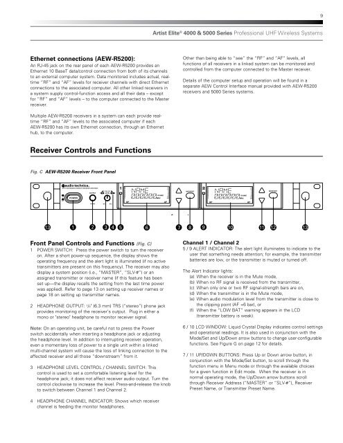
9Artist Elite ® <strong>4000</strong> & <strong>5000</strong> <strong>Series</strong> Professional UHF Wireless SystemsEthernet connections (AEW-R5200):An RJ-45 jack on the rear panel of each AEW-R5200 provides anEthernet 10 BaseT data/control connection from both of its channelsto an external computer system. Data monitored includes actual, realtime“RF” and “AF” levels for receiver channels with direct Ethernetconnections to the associated computer. All other linked receivers ina system supply control-function access and all their data – exceptfor “RF” and “AF” levels – to the computer connected to the Masterreceiver.Other than being able to “see” the “RF” and “AF” levels, allfunctions of all receivers in a linked system can be monitored andcontrolled from the computer connected to the Master receiver.Details of the computer setup and operation will be found in aseparate AEW Control Interface manual provided with AEW-R5200receivers and <strong>5000</strong> <strong>Series</strong> systems.Multiple AEW-R5200 receivers in a system can each provide realtime“RF” and “AF” levels to the associated computer if eachAEW-R5200 has its own Ethernet connection, through an Ethernethub, to the computer.Receiver Controls and FunctionsFig. C AEW-R5200 Receiver Front PanelUHF SYNTHESIZED DIVERSITY RECEIVER AEW-R5200OUTPUTPUSH SELLEVELMODE/SETMODE/SETONPOWERRX NAMERX NAMEOFFPHONESMINMAX13 1 2 3 4 5 6 7 8 9 10 11 12 13ININSTRUMENTMIC OUTPUTFront Panel Controls and Functions (Fig. C)NETWORKANT. BINTERFACEANT. A1 POWER SWITCH: Press the power ATTN (dB) switch to turn the receiverEXTERNAL OUTPUTGROUND GROUNDMUTE(BAL)LIFTon. After a short power-up sequence, the display shows theoperating frequency and the alert light is illuminated (if no activetransmitters are present on this frequency). The receiver may alsodisplay a system position (i.e., “MASTER”, “SLV-#”) or anassigned transmitter or receiver name (if this feature has beenset up—the display recalls the setting from the last time powerwas applied). Refer to page 13 on setting up receiver names orpage 18 on setting up transmitter names.2 HEADPHONE OUTPUT: 1 /4" (6.3 mm) TRS (“stereo”) phone jackprovides monitoring of the receiver’s output. Plug in either amono or "stereo" headphone to monitor receiver signal.Note: On an operating unit, be careful not to press the Powerswitch accidentally when inserting a headphone jack or adjustingthe headphone level. In addition to interrupting receiver operation,even a momentary loss of power to a single unit within a linkedmulti-channel system will cause the loss of linking connection to theaffected receiver and all those “downstream” from it.3 HEADPHONE LEVEL CONTROL / CHANNEL SWITCH: Thiscontrol is used to set a comfortable listening level for theheadphone jack; it does not affect receiver audio output. Turn thecontrol clockwise to increase the level. Press-and-release the knobto switch between Channel 1 and Channel 2.0/-6/-12BALANCEDINEXTERNALMUTEMIC OUTPUT50/60HzChannel 1 / Channel 2OUTPUTLINK5A/500W MAX0/-6/-125 / 9 ALERT INDICATOR: The alert light illuminates WARNING: to indicate to theATTN (dB)THIS APPARATUSGROUND GROUNDOUTMUST BE EARTHED.user that something LIFT needs attention; for example, the transmitterbatteries are low, or the transmitter is muted or turned off.INSTRUMENTOUTPUT(BAL)BALANCEDINThe Alert Indicator lights:(a) When the receiver is in the Mute mode,(b) When no RF signal is received from the transmitter,(c) When only one or two RF signal-strength bars are on,(d) When the transmitter is in the Mute mode,(e) When audio modulation level from the transmitter is close tothe clipping point (AF +6 bar), or(f) When the “LOW BAT” warning appears in the LCD(transmitter battery is weak).6 / 10 LCD WINDOW: Liquid Crystal Display indicates control settingsand operational readings. It is also used in conjunction with theMode/Set and Up/Down arrow buttons to change user-configurablefunctions. See Figure G on page 12 for details.100V-240VAC˜7 / 11 UP/DOWN BUTTONS: Press Up or Down arrow button, inconjunction with the Mode/Set button, to scroll through thefunction menu in Menu mode or through the available choicesfor a given function in Edit mode. When the receiver is innormal operating mode, the Up/Down arrow buttons scrollthrough Receiver Address (“MASTER” or “SLV-#”), ReceiverPreset Name, or Transmitter Preset Name.4 HEADPHONE CHANNEL INDICATOR: Shows which receiverchannel is feeding the monitor headphones.