4000 & 5000 Series Owners Manual - Audio-Technica
4000 & 5000 Series Owners Manual - Audio-Technica
4000 & 5000 Series Owners Manual - Audio-Technica

Create successful ePaper yourself
Turn your PDF publications into a flip-book with our unique Google optimized e-Paper software.
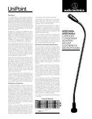
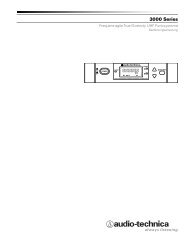
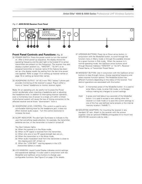
11Artist Elite ® <strong>4000</strong> & <strong>5000</strong> <strong>Series</strong> Professional UHF Wireless SystemsFig. E AEW-R4100 Receiver Front PanelONOFFPOWERALERTMODE/SETRX NAMEPHONESMIN–LEVEL–MAXUHF SYNTHESIZED DIVERSITY RECEIVER AEW-R410039 33 32 34 35 3637 3839Front Panel Controls and Functions (Fig. E)32 POWER SWITCH: Press the power switch to turn the receiveron. After a short power-up sequence, the display shows theoperating frequency and the alert light is illuminated (if no activetransmitters are present on this frequency). The receiver may alsodisplay a system position (i.e., “MASTER”, “SLV-#”) or anassigned transmitter or receiver name (if this feature has beenset up—the display recalls the setting from the last time powerwas applied). Refer to page 13 on setting up receiver names orpage 18 on setting up transmitter names.33 HEADPHONE OUTPUT: 1/4" (6.3 mm) TRS (“stereo”) phone jackprovides monitoring of the receiver’s output. Plug in either amono or "stereo" headphone to monitor receiver signal.Note: On an operating unit, be careful not to press the Powerswitch accidentally when inserting a headphone jack or adjustingthe headphone level. In addition to interrupting receiver operation,even a momentary loss of power to a single unit within a linkedmulti-channel system will cause the loss of linking connection to theaffected receiver and all those “downstream” from it.34 HEADPHONE LEVEL CONTROL: This control is used to set acomfortable listening level for the headphone jack; it does notaffect receiver audio output. Turn the control clockwise toincrease the level.35 ALERT INDICATOR: The alert light illuminates to indicate to theuser that something needs attention; for example, the transmitterbatteries are low, or the transmitter is muted or turned off.BALANCEDINMIC OUTPUTININSTRUMENT37 UP/DOWN BUTTONS: Press Up or Down arrow button, in0/-6/-12ANT. BANT. AAC˜ 100V-240VATTN (dB)50/60HzOUTPUTGROUND GROUND IN – LINK – OUT WARNING:(UNBAL.)LIFTTHIS APPARATUS MUST BE EARTHED.conjunction with the Mode/Set button, to scroll through thefunction menu in Menu mode or through the available choicesfor a given function in Edit mode. When the receiver is innormal operating mode, the Up/Down arrow buttons scrollthrough Receiver Address (“MASTER” or “SLV-#”), ReceiverPreset Name, or Transmitter Preset Name.38 MODE/SET BUTTON: Use in conjunction with the Up/Down arrowbuttons to step through menus, choose operating frequency andselect receiver function options. The Mode/Set button hasdifferent functions depending on the status of the receiver. Twodistinct operations are associated with this button:Touch:Hold:A momentary press of the Mode/Set button. It is used toenter Menu mode, to enter Edit mode, or to Escapewithout making any changes to current settings.A press and hold (about two seconds) of the Mode/Setbutton. It is used to accept a new setting when thereceiver is in Edit mode or to save the current settings toone of the five user-defined name presets or the internalmemory location (“NAME?”).39 MOUNTING ADAPTERS: For mounting the receiver in anystandard 19" rack. Attach to the receiver with the screwssupplied. (Use an optional AT8628a joining-plate kit to mount twoAEW-R4100 receivers side by side.)The Alert Indicator lights:(a) When the receiver is in the Mute mode,(b) When no RF signal is received from the transmitter,(c) When only one or two RF signal-strength bars are on,(d) When the transmitter is in the Mute mode,(e) When audio modulation level from the transmitter is close tothe clipping point (AF +6 bar), or(f) When the “LOW BAT” warning appears in the LCD(transmitter battery is weak).36 LCD WINDOW: Liquid Crystal Display indicates control settingsand operational readings. It is also used in conjunction with theMode/Set and Up/Down arrow buttons to change userconfigurablefunctions. See Figure G on page 12 for details.