4000 & 5000 Series Owners Manual - Audio-Technica
4000 & 5000 Series Owners Manual - Audio-Technica
4000 & 5000 Series Owners Manual - Audio-Technica
Create successful ePaper yourself
Turn your PDF publications into a flip-book with our unique Google optimized e-Paper software.
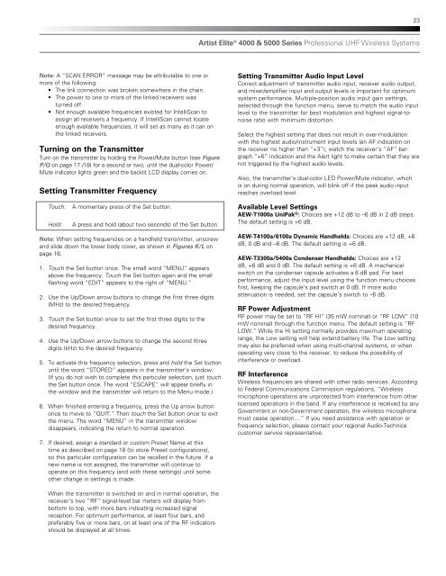
23Artist Elite ® <strong>4000</strong> & <strong>5000</strong> <strong>Series</strong> Professional UHF Wireless SystemsNote: A “SCAN ERROR” message may be attributable to one ormore of the following:• The link connection was broken somewhere in the chain.• The power to one or more of the linked receivers wasturned off.• Not enough available frequencies existed for IntelliScan toassign all receivers a frequency. If IntelliScan cannot locateenough available frequencies, it will set as many as it can onthe linked receivers.Turning on the TransmitterTurn on the transmitter by holding the Power/Mute button (see FigureP/Q on page 17 /18) for a second or two, until the dual-color Power/Mute indicator lights green and the backlit LCD display comes on.Setting Transmitter FrequencySetting Transmitter <strong>Audio</strong> Input LevelCorrect adjustment of transmitter audio input, receiver audio output,and mixer/amplifier input and output levels is important for optimumsystem performance. Multiple-position audio input gain settings,selected through the function menu, serve to match the audio inputlevel to the transmitter for best modulation and highest signal-tonoiseratio with minimum distortion.Select the highest setting that does not result in over-modulationwith the highest audio/instrument input levels (an AF indication onthe receiver no higher than “+3”); watch the receiver’s “AF” bargraph“+6” indication and the Alert light to make certain that they arenot triggered by the highest audio levels.Also, the transmitter’s dual-color LED Power/Mute indicator, whichis on during normal operation, will blink off if the peak audio inputreaches overload level.Touch:Hold:A momentary press of the Set button.A press and hold (about two seconds) of the Set button.Available Level SettingsAEW-T1000a UniPak ® : Choices are +12 dB to –6 dB in 2 dB steps.The default setting is +6 dB.Note: When setting frequencies on a handheld transmitter, unscrewand slide down the lower body cover, as shown in Figures K/L onpage 16.1. Touch the Set button once. The small word “MENU” appearsabove the frequency. Touch the Set button again and the smallflashing word “EDIT” appears to the right of “MENU.”2. Use the Up/Down arrow buttons to change the first three digits(MHz) to the desired frequency.3. Touch the Set button once to set the first three digits to thedesired frequency.4. Use the Up/Down arrow buttons to change the second threedigits (kHz) to the desired frequency.5. To activate this frequency selection, press and hold the Set buttonuntil the word “STORED” appears in the transmitter’s window.(If you do not wish to complete this particular selection, just touchthe Set button once. The word “ESCAPE” will appear briefly inthe window and the transmitter will return to the Menu mode.)6. When finished entering a frequency, press the Up arrow buttononce to move to “QUIT.” Then touch the Set button once to exitthe menu. The word “MENU” in the transmitter windowdisappears, indicating the return to normal operation.7. If desired, assign a standard or custom Preset Name at thistime as described on page 18 (to store Preset configurations),so this particular configuration can be recalled in the future. If anew name is not assigned, the transmitter will continue tooperate on this frequency (and with these settings) until someother change in settings is made.AEW-T4100a/6100a Dynamic Handhelds: Choices are +12 dB, +6dB, 0 dB and –6 dB. The default setting is +6 dB.AEW-T3300a/5400a Condenser Handhelds: Choices are +12dB, +6 dB and 0 dB. The default setting is +6 dB. A mechanicalswitch on the condenser capsule activates a 6 dB pad. For bestperformance, adjust the input level using the function menu choicesfirst, keeping the capsule’s pad switch at 0 dB. If more audioattenuation is needed, set the capsule’s switch to –6 dB.RF Power AdjustmentRF power may be set to “RF HI” (35 mW nominal) or “RF LOW” (10mW nominal) through the function menu. The default setting is “RFLOW.” While the Hi setting normally provides maximum operatingrange, the Low setting will help extend battery life. The Low settingmay also be preferred when using multi-channel systems, or whenoperating very close to the receiver, to reduce the possibility ofinterference or overload.RF InterferenceWireless frequencies are shared with other radio services. Accordingto Federal Communications Commission regulations, “Wirelessmicrophone operations are unprotected from interference from otherlicensed operations in the band. If any interference is received by anyGovernment or non-Government operation, the wireless microphonemust cease operation....” If you need assistance with operation orfrequency selection, please contact your regional <strong>Audio</strong>-<strong>Technica</strong>customer service representative.When the transmitter is switched on and in normal operation, thereceiver’s two “RF” signal-level bar meters will display frombottom to top, with more bars indicating increased signalreception. For optimum performance, at least four bars, andpreferably five or more bars, on at least one of the RF indicatorsshould be displayed at all times.


