Mechatronic Design of a Soccer Robot for the Small-Size League of ...
Mechatronic Design of a Soccer Robot for the Small-Size League of ...
Mechatronic Design of a Soccer Robot for the Small-Size League of ...

You also want an ePaper? Increase the reach of your titles
YUMPU automatically turns print PDFs into web optimized ePapers that Google loves.
FACULTEIT INGENIEURSWETENSCHAPPEN<br />
<strong>Mechatronic</strong> <strong>Design</strong> <strong>of</strong> a <strong>Soccer</strong><br />
<strong>Robot</strong> <strong>for</strong> <strong>the</strong> <strong>Small</strong>-<strong>Size</strong> <strong>League</strong><br />
<strong>of</strong> RoboCup<br />
Joris De Witte<br />
Promotor: Pr<strong>of</strong>. Dr. Ir. Bram Vanderborght<br />
Eindwerk ingediend voor het behalen van de graad van Master in de<br />
Ingenieurswetenschappen: Werktuigbouwkunde<br />
Academiejaar 2009-2010
Acknowledgments<br />
At <strong>the</strong> end <strong>of</strong> my first year at <strong>the</strong> VUB, <strong>the</strong> course ‘mechatronica’ aroused my interest<br />
in robotic systems. During this course, a small robot was built to develop our skills in<br />
this matter. With <strong>the</strong> gained knowledge, I decided to choose <strong>the</strong> <strong>the</strong>sis subject <strong>of</strong><br />
building a robot <strong>for</strong> <strong>the</strong> RoboCup <strong>Small</strong> <strong>Size</strong> <strong>League</strong>. I consider it as a privilege to be<br />
able to give a contribution in <strong>the</strong> development <strong>of</strong> <strong>the</strong>se robots.<br />
I would like to thank my promoter Dr. Ir. Bram Vanderborght <strong>for</strong> his support, guidance<br />
and enthusiasm <strong>for</strong> this subject. Many thanks go out to Jean-Paul Schepens and Ir.<br />
Ronald Van Ham <strong>for</strong> <strong>the</strong>ir time and help <strong>the</strong>y gave along <strong>the</strong> way. Also, I would like to<br />
thank <strong>the</strong> people <strong>of</strong> <strong>the</strong> workshop: Marnix and Stijn <strong>for</strong> <strong>the</strong>ir technical assistance and<br />
sharing <strong>the</strong>ir experience.<br />
As last, I would like to thank my family <strong>for</strong> <strong>the</strong>ir moral support.<br />
The auteur:<br />
Joris De Witte
Executive summaries<br />
1. Mechatronisch ontwerp van een voetbalrobot voor de<br />
RoboCup <strong>Small</strong> <strong>Size</strong> <strong>League</strong><br />
In deze <strong>the</strong>sis wordt het mechatronisch ontwerp van een voetbalrobot behandeld. De<br />
robots die deelnemen aan deze competitie doorgingen in de loop der jaren een sterke<br />
miniaturisering. Het implementeren van alle componenten in een beperkte ruimte is<br />
dan ook de uitdaging van deze <strong>the</strong>sis.<br />
Om een idee te hebben van de bestaande technologie werd voor iedere mechanische<br />
component een vergelijking gemaakt tussen de bestaande robots. Hieruit blijkt dat de<br />
deelnemende teams vergelijkbare componenten en technologieën gebruiken in hun<br />
robots. Toch kunnen enkele teams het verschil maken door een goed ontwerp en<br />
integratie van de componenten.<br />
De ontworpen robot maakt gebruik van vier gelijkstroommotoren met elektronische<br />
commutatie voor de aandrijving. Via een tandwieloverbrenging wordt de kracht<br />
overgebracht naar de onmindirectionele wielen.<br />
Om de bal weg te kunnen trappen, wordt een schietsysteem ingebouwd. Deze bestaat<br />
uit een veer die opgespannen wordt. Een sluitsysteem houdt de plunjer vast terwijl de<br />
veer wordt opgespannen. Een servomotor bedient dit sluitsysteem en kan de plunjer<br />
vrijmaken wanneer er getrapt moet worden.<br />
Een dribbelsysteem brengt de bal naar het midden van de robot en houdt de bal ook<br />
voor de robot terwijl er gemanoeuvreerd kan worden met de robot. Deze bestaat uit<br />
een sneldraaiende cilinder dewelke een backspin geeft aan de bal.<br />
Alle mechanische en elektronische systemen werden ontwikkeld en getest. Dit vormt<br />
een eerste stap naar het ontwikkelen van een complete robot, geschikt voor de<br />
deelname aan de RoboCup <strong>Small</strong> <strong>Size</strong> <strong>League</strong> hetgeen ook het doel is van deze <strong>the</strong>sis.
2. <strong>Mechatronic</strong> design <strong>of</strong> a soccer playing robot <strong>for</strong> <strong>the</strong><br />
RoboCup <strong>Small</strong> <strong>Size</strong> <strong>League</strong><br />
In this <strong>the</strong>sis, <strong>the</strong> design <strong>of</strong> a soccer-playing robot is discussed. The robots that<br />
participate in this competition are a result <strong>of</strong> a strong miniaturization during <strong>the</strong> years.<br />
The implementation <strong>of</strong> all components in a limited amount <strong>of</strong> space is <strong>the</strong>re<strong>for</strong>e <strong>the</strong><br />
challenge <strong>of</strong> this <strong>the</strong>sis.<br />
To have a notion <strong>of</strong> <strong>the</strong> existing technologies, a comparison was made between all<br />
competing robots <strong>for</strong> each mechanical component. This shows that <strong>the</strong> participating<br />
teams use similar components and technologies. Never<strong>the</strong>less, some teams can make<br />
<strong>the</strong> difference with well designed components.<br />
The developed robot uses four brushless DC motors with electronic commutation <strong>for</strong><br />
<strong>the</strong> drive unit. Via a spur-gear transmission, <strong>the</strong> power is transmitted to <strong>the</strong> omnidirectional<br />
wheels.<br />
To kick <strong>the</strong> ball, a shooting device is built. This system consists <strong>of</strong> a spring which is<br />
wound up. A lock/release system hold <strong>the</strong> plunger in place while winding up <strong>the</strong><br />
spring. A servomotor actuates <strong>the</strong> lock/release system when a kick is required.<br />
A dribbler device brings <strong>the</strong> ball to <strong>the</strong> center <strong>of</strong> <strong>the</strong> robot and hold <strong>the</strong> ball in front <strong>of</strong><br />
<strong>the</strong> robot when it is maneuvering. The dribbler is a cylinder which spins with great<br />
speed and gives a backspin to <strong>the</strong> ball.<br />
All mechanical and electronic components where developed and tested. This is a first<br />
step to developing a complete robot, fit <strong>for</strong> <strong>the</strong> RoboCup <strong>Small</strong> <strong>Size</strong> <strong>League</strong> which is<br />
<strong>the</strong> goal <strong>of</strong> this <strong>the</strong>sis.
Contents<br />
1 Introduction ................................................................................................... 1<br />
1.1 RoboCup ............................................................................................................................... 1<br />
1.2 Objectives.............................................................................................................................. 2<br />
2 Driving unit ................................................................................................... 4<br />
2.1 State <strong>of</strong> <strong>the</strong> art ...................................................................................................................... 4<br />
2.2 Omni-directional wheels ....................................................................................................... 6<br />
2.2.1 Number <strong>of</strong> wheels................................................................................................................... 6<br />
2.2.2 Dimensions <strong>of</strong> <strong>the</strong> wheel ......................................................................................................... 7<br />
2.2.3 Concepts <strong>of</strong> construction ....................................................................................................... 10<br />
2.2.4 Final design .......................................................................................................................... 14<br />
2.3 Driving Motors ................................................................................................................... 15<br />
2.4 Transmission unit ............................................................................................................... 16<br />
2.4.1 General................................................................................................................................. 16<br />
2.4.2 Spur gear .............................................................................................................................. 17<br />
2.4.3 Belt transmission .................................................................................................................. 17<br />
2.4.4 Final design .......................................................................................................................... 17<br />
2.5 Experiments ........................................................................................................................ 19<br />
2.6 Conclusions ......................................................................................................................... 20<br />
3 Kicking device ............................................................................................. 21<br />
3.1 General................................................................................................................................ 21<br />
3.2 State <strong>of</strong> <strong>the</strong> art .................................................................................................................... 21<br />
3.3 Types <strong>of</strong> shooting devices .................................................................................................... 22<br />
3.3.1 Solenoid actuated.................................................................................................................. 22<br />
3.3.2 Spring actuated ..................................................................................................................... 23<br />
3.3.3 Pneumatic actuated ............................................................................................................... 24<br />
3.3.4 O<strong>the</strong>r .................................................................................................................................... 24<br />
3.4 Shooting system model........................................................................................................ 25<br />
3.4.1 General................................................................................................................................. 25<br />
3.4.2 Application note ................................................................................................................... 32<br />
3.5 First construction ................................................................................................................ 39<br />
3.6 Second construction ............................................................................................................ 41<br />
3.7 Experiments ........................................................................................................................ 44<br />
3.7.1 Compression process ............................................................................................................ 45<br />
3.7.2 Releasing process ................................................................................................................. 46<br />
3.8 Conclusions ......................................................................................................................... 48<br />
4 Dribbler ....................................................................................................... 49<br />
4.1 General................................................................................................................................ 49<br />
4.2 State <strong>of</strong> <strong>the</strong> art .................................................................................................................... 49<br />
4.3 Dimensions <strong>of</strong> <strong>the</strong> dribbler ................................................................................................. 51<br />
4.4 <strong>Design</strong> .................................................................................................................................. 53<br />
4.5 Experiments ........................................................................................................................ 54<br />
4.6 Conclusions ......................................................................................................................... 55
5 Electronics ................................................................................................... 56<br />
5.1 Motor controller ................................................................................................................. 56<br />
5.1.1 Brushless DC drive motors controller .................................................................................... 56<br />
5.1.2 Brushed motor <strong>for</strong> kicking device and dribbler ...................................................................... 58<br />
5.2 Interface electronics ............................................................................................................ 59<br />
5.2.1 FPGA ................................................................................................................................... 59<br />
5.2.2 Voltage regulation ................................................................................................................ 59<br />
5.3 Experiments ........................................................................................................................ 60<br />
5.4 Conclusions ......................................................................................................................... 60<br />
6 S<strong>of</strong>tware ....................................................................................................... 61<br />
6.1 Motion control .................................................................................................................... 61<br />
6.1.1 General................................................................................................................................. 61<br />
6.1.2 Electronic compass ............................................................................................................... 62<br />
6.1.3 Motor speed estimation ......................................................................................................... 63<br />
6.1.4 Motor control ....................................................................................................................... 64<br />
6.2 Kicking device control ........................................................................................................ 67<br />
6.3 Dribbler control .................................................................................................................. 67<br />
6.4 Conclusions ......................................................................................................................... 68<br />
7 Conclusions and fur<strong>the</strong>r work .................................................................... 69<br />
7.1 Conclusions ......................................................................................................................... 69<br />
7.2 Fur<strong>the</strong>r work ...................................................................................................................... 71<br />
8 Appendix ...................................................................................................... 72<br />
8.1 Appendix A: Rules <strong>of</strong> play .................................................................................................. 72<br />
8.1.1 External equipment provided by RoboCup ............................................................................ 72<br />
8.1.2 <strong>Robot</strong> and internal equipment ............................................................................................... 73<br />
8.2 Appendix B: CD rom .......................................................................................................... 80<br />
9 Bibliography ................................................................................................ 81<br />
9.1 Team description papers .................................................................................................... 81<br />
9.2 Books ................................................................................................................................... 83<br />
9.3 Papers ................................................................................................................................. 83<br />
9.4 Websites .............................................................................................................................. 83<br />
9.5 Datasheets ........................................................................................................................... 83
List <strong>of</strong> figures<br />
Figure 1: RoboCup competition layout ...................................................................................... 2<br />
Figure 2: Calculation <strong>of</strong> loss in ground surface .......................................................................... 7<br />
Figure 3: Loss in ground surface <strong>of</strong> <strong>the</strong> robot compared to wheel diameter ................................ 9<br />
Figure 4: Rotacaster omniwheel .............................................................................................. 10<br />
Figure 5: Omniwheel-design by Parsian team[15] .................................................................... 11<br />
Figure 6: Kiks research[10]: Various types <strong>of</strong> small wheels design .......................................... 11<br />
Figure 7:Kiks research[10]: Average time to reach 1m/s from static condition <strong>for</strong> <strong>the</strong> robot ..... 12<br />
Figure 8: Omniwheel-design by Korea University [27]............................................................ 13<br />
Figure 9: New omniwheel-design ............................................................................................ 14<br />
Figure 10: Maxon EC 45, 30Watt motor .................................................................................. 15<br />
Figure 11: Structural design <strong>of</strong> transmission units .................................................................... 18<br />
Figure 12: Close-up <strong>of</strong> front transmission unit with spur gears………………………………………………. 23<br />
Figure 13: Close-up <strong>of</strong> rear transmission unit with pulley ...................................................... 19<br />
Figure 14: Shooting system release process parameters ........................................................... 28<br />
Figure 15: Compressed spring length as function <strong>of</strong> <strong>the</strong> time ................................................... 33<br />
Figure 16: Compression time with selected spring ................................................................... 34<br />
Figure 17: Plunger and ball speed as function <strong>of</strong> time .............................................................. 35<br />
Figure 18: Plunger velocity as function <strong>of</strong> <strong>the</strong> spring length ..................................................... 36<br />
Figure 19: Plunger acceleration as function <strong>of</strong> <strong>the</strong> spring length ............................................... 36<br />
Figure 20: Ball velocity as function <strong>of</strong> plunger mass ................................................................ 37<br />
Figure 21: Effect <strong>of</strong> <strong>the</strong> plunger <strong>of</strong>fset ..................................................................................... 38<br />
Figure 22: First shooting system, general overview ................................................................. 39<br />
Figure 23: First shooting system: view on <strong>the</strong> spindle .............................................................. 39<br />
Figure 24: First shooting system: close-up on <strong>the</strong> displacement nut (left) and guidance bush.... 40<br />
Figure 25: First shooting system, close-up on <strong>the</strong> release ring .................................................. 41<br />
Figure 26: Second shooting system, general overview ............................................................. 41
Figure 27: Second shooting system, view on <strong>the</strong> plunger and spindle ....................................... 42<br />
Figure 28: Second shooting system, close-up on <strong>the</strong> guidance bush and footstep bearing ......... 42<br />
Figure 29: Second shooting system, view on <strong>the</strong> release ring and servomotor .......................... 43<br />
Figure 30: Dribbler setup ........................................................................................................ 51<br />
Figure 31: Dribbler components .............................................................................................. 53<br />
Figure 32: Dribbler experiment ............................................................................................... 54<br />
Figure 33: Block commutation <strong>for</strong> brushless DC motor [30] .................................................... 56<br />
Figure 34: Electronic circuit <strong>for</strong> brushless motor [30] .............................................................. 57<br />
Figure 35: H-bridge <strong>for</strong> brushed motor .................................................................................... 58<br />
Figure 36: Hitachi HM55B connection scheme ........................................................................ 62<br />
Figure 37: Speed estimation using <strong>the</strong> L6235 motor driver ...................................................... 63<br />
Figure 38: <strong>Robot</strong> layout <strong>for</strong> motor control ............................................................................... 64<br />
Figure 39: Experimental results <strong>for</strong> modified kinematics per<strong>for</strong>med by Skuba-team [22] ......... 66<br />
Figure 40: Layout <strong>of</strong> <strong>the</strong> playing field...................................................................................... 72<br />
Figure 41: Maximum dimensions <strong>of</strong> <strong>the</strong> robot ......................................................................... 73<br />
Figure 42: Dimensions <strong>of</strong> <strong>the</strong> recognition pattern..................................................................... 75<br />
Figure 43: Legal color assignments ......................................................................................... 76<br />
Figure 44: 20% rule................................................................................................................. 77
List <strong>of</strong> tables<br />
Table 1: Comparison <strong>of</strong> RoboCup Teams: Driving unit ............................................................. 4<br />
Table 2: Comparison between number <strong>of</strong> wheels ....................................................................... 6<br />
Table 3: Comparison between RoboCup teams: Kicking device ............................................... 21<br />
Table 4: Shooting system components ..................................................................................... 32<br />
Table 5: Adapted values from ma<strong>the</strong>matical model .................................................................. 44<br />
Table 6: Winding time measurements ...................................................................................... 45<br />
Table 7: Ball velocity measurements ....................................................................................... 47<br />
Table 8: Comparison between RoboCup teams: Dribbler ......................................................... 49<br />
Table 9: Electronic compass commands .................................................................................. 62
Chapter 1: Introduction<br />
1 Introduction<br />
1.1 RoboCup<br />
RoboCup[29] is a competition domain designed to advance robotics and artificial<br />
intelligence research through a friendly competition. <strong>Small</strong> <strong>Size</strong> robot soccer is one<br />
<strong>of</strong> <strong>the</strong> RoboCup league divisions. <strong>Small</strong> <strong>Size</strong> robot soccer, or F180 as it is o<strong>the</strong>rwise<br />
known, focuses on <strong>the</strong> problem <strong>of</strong> intelligent multi-agent cooperation and control in<br />
a highly dynamic environment with a hybrid centralized/distributed control system.<br />
A <strong>Small</strong> <strong>Size</strong> robot soccer game takes place between two teams <strong>of</strong> five robots each.<br />
Each robot must be made con<strong>for</strong>m to <strong>the</strong> dimensions as specified in <strong>the</strong> F180 rules:<br />
The robot must fit within an 180mm diameter circle and must be no higher than<br />
150mm unless <strong>the</strong>y use on-board vision. The robots play soccer with an orange golf<br />
ball on a green carpeted field that is 6.05m long by 4.05m wide. <strong>Robot</strong>s come in two<br />
flavors, those with local on-board vision sensors and those with global vision. Global<br />
vision robots, by far <strong>the</strong> most common variety, use an overhead camera and <strong>of</strong>ffield<br />
PC to identify and track <strong>the</strong> robots as <strong>the</strong>y move around <strong>the</strong> field. The<br />
overhead camera is attached to a camera bar located 4m above <strong>the</strong> playing surface.<br />
Local vision robots have <strong>the</strong>ir sensing on <strong>the</strong> robot itself. The vision in<strong>for</strong>mation is<br />
ei<strong>the</strong>r processed on-board <strong>the</strong> robot or is transmitted back to <strong>the</strong> <strong>of</strong>f-field PC <strong>for</strong><br />
processing. An <strong>of</strong>f-field PC is used to communicate referee commands and, in <strong>the</strong><br />
case <strong>of</strong> overhead vision, position in<strong>for</strong>mation to <strong>the</strong> robots. Typically <strong>the</strong> <strong>of</strong>f-field PC<br />
also per<strong>for</strong>ms most, if not all, <strong>of</strong> <strong>the</strong> processing required <strong>for</strong> coordination and<br />
control <strong>of</strong> <strong>the</strong> robots. Communications is wireless and typically uses dedicated<br />
commercial FM transmitter/receiver units.<br />
1
Chapter 1: Introduction<br />
Figure 1: RoboCup competition layout<br />
Building a successful team requires clever design, implementation and integration<br />
<strong>of</strong> many hardware and s<strong>of</strong>tware sub-components into a robustly functioning<br />
system. This makes small-size robot soccer a very interesting and challenging<br />
domain <strong>for</strong> research and education.<br />
1.2 Objectives<br />
The design <strong>of</strong> a complete robotic system to compete in <strong>the</strong> RoboCup <strong>Small</strong> <strong>Size</strong><br />
<strong>League</strong> involves <strong>the</strong> integration <strong>of</strong> different areas <strong>of</strong> knowledge.<br />
In order to do so, a team with members <strong>of</strong> several Belgian universities is<br />
established. Each member works on a subproject which is related to <strong>the</strong>ir area <strong>of</strong><br />
knowledge.<br />
2
Chapter 1: Introduction<br />
The goal <strong>of</strong> a first subproject is to develop a s<strong>of</strong>tware plat<strong>for</strong>m <strong>for</strong> <strong>the</strong> high level<br />
control. All <strong>the</strong> strategic actions are embedded in <strong>the</strong> s<strong>of</strong>tware. The s<strong>of</strong>tware<br />
determines all <strong>the</strong> necessary actions <strong>the</strong> robots must undertake to win <strong>the</strong> game.<br />
A second subproject has <strong>the</strong> goal <strong>of</strong> processing <strong>the</strong> data from <strong>the</strong> overhead camera.<br />
The location <strong>of</strong> each robot, <strong>the</strong> robots ID and <strong>the</strong> ball location have to be<br />
determined.<br />
The goal <strong>of</strong> this <strong>the</strong>sis is to develop <strong>the</strong> mechatronic design <strong>of</strong> <strong>the</strong> small-size robot<br />
This robot houses all <strong>the</strong> systems to handle <strong>the</strong> ball and to communicate with <strong>the</strong><br />
<strong>of</strong>f-field PC. Be<strong>for</strong>e developing <strong>the</strong> robot, all requirements and limitations have to<br />
be known. In Appendix 1: <strong>the</strong> rules provided by RoboCup are summarized. These<br />
rules set <strong>the</strong> design specifications.<br />
A first major component <strong>of</strong> <strong>the</strong> robot is <strong>the</strong> drive system which includes <strong>the</strong> motors,<br />
<strong>the</strong> transmission system and a set <strong>of</strong> omni-directional wheels. These are discussed<br />
in ‘chapter 2: Drive Unit’.<br />
The second component <strong>of</strong> <strong>the</strong> robot is a system to kick <strong>the</strong> ball. A state <strong>of</strong> <strong>the</strong> art <strong>of</strong><br />
existing systems is discussed in ‘chapter 3: Kicking device’. The benefits and<br />
disadvantages <strong>of</strong> all <strong>the</strong>se systems are summarized. With this knowledge in mind, a<br />
new concept is developed.<br />
Ano<strong>the</strong>r component is <strong>the</strong> dribbler. This system has <strong>the</strong> task <strong>of</strong> giving a backspin to<br />
<strong>the</strong> ball. With this system, <strong>the</strong> robot is able to hold <strong>the</strong> ball in front <strong>of</strong> it and thus<br />
handle <strong>the</strong> ball better. This system is discussed in ‘chapter 4: Dribbler’.<br />
For this <strong>the</strong>sis, <strong>the</strong> electronics on board <strong>of</strong> <strong>the</strong> robot are all united into ‘chapter 5:<br />
electronics’. This chapter discusses all <strong>the</strong> motor-controllers and a component <strong>for</strong><br />
navigational purpose.<br />
In order to control <strong>the</strong> robot some s<strong>of</strong>tware has to be developed. The commands<br />
from <strong>the</strong> <strong>of</strong>f-field PC have to be translated to <strong>the</strong> different motors on <strong>the</strong> robot. In<br />
‘chapter 6: S<strong>of</strong>tware’, this is discussed.<br />
The last chapter provides <strong>the</strong> conclusions and future work.<br />
3
Chapter 2: Drive unit<br />
2 Driving unit<br />
2.1 State <strong>of</strong> <strong>the</strong> art<br />
Be<strong>for</strong>e discussing and constructing a drive system, <strong>the</strong> existing systems are<br />
reviewed. The next table gives an overview <strong>of</strong> <strong>the</strong>se systems, currently used in<br />
robots competing in <strong>the</strong> RoboCup <strong>Small</strong> <strong>Size</strong> <strong>League</strong>. Top teams from <strong>the</strong> last three<br />
years are printed in bold. More in<strong>for</strong>mation about <strong>the</strong> type <strong>of</strong> wheels can be found<br />
in next paragraphs.<br />
Table 1: Comparison <strong>of</strong> RoboCup Teams: Driving unit<br />
Team<br />
Number<br />
<strong>of</strong><br />
Type<br />
<strong>of</strong><br />
Motors Power Speed Spur gear<br />
ratio<br />
wheels wheels<br />
Botania Dragon 4 Brushless DC 30 W<br />
Knights [1]<br />
Brocks [2] 4 <strong>Small</strong> Brushless DC 30 W 3:1<br />
B-Smart [3] 4 <strong>Small</strong> Faulhaber 20,5 W 9000 12:1<br />
2342S006CR<br />
Brushed DC<br />
rpm<br />
CMDragons [4] 4 <strong>Small</strong> Brushless DC 30 W<br />
Eagle Knights [5] 4 <strong>Small</strong> Faulhaber<br />
14:1<br />
2224P0212<br />
ER-Force [6] 4 <strong>Small</strong> Maxon EC 45 30 W<br />
(New system)<br />
Brushless DC<br />
Field Rangers [7] 4 <strong>Small</strong> Faulhaber 9,35 W 7400 9,7:1<br />
2232U009SR<br />
rpm<br />
Immortals [8] 4 <strong>Small</strong> Maxon EC 45 50 W 45:12<br />
Brushless DC<br />
Khainui [9] 4 <strong>Small</strong> Namiki 22CL-<br />
10:1<br />
3501PG80:1<br />
KIKS [10] 4 <strong>Small</strong> Maxon EC 45<br />
Brushless DC<br />
3,6:1<br />
4
Chapter 2: Drive unit<br />
KN2C [11] 3 <strong>Small</strong> Brushed DC 8160 13,6:1<br />
rpm<br />
ODENS [12] 4 <strong>Small</strong> Maxon REmax<br />
11 W 8290 7,916:1<br />
23<br />
Brushed DC<br />
rpm<br />
OMID [13] 4 <strong>Small</strong> Maxon EC 45 30 W 5:1<br />
Brushless DC<br />
Owaribito [14] 4 <strong>Small</strong> Maxon RE-max<br />
21<br />
Brushed DC<br />
Parsian [15] 4 <strong>Small</strong> Maxon EC 45 30 W 4.7:1<br />
Brushless DC<br />
RFC Cambridge 4 <strong>Small</strong> Brushless DC<br />
[16]<br />
Robojackets [17] 3 <strong>Small</strong> Maxon EC 45<br />
4,5:1<br />
Brushless DC<br />
Robodragons 4 <strong>Small</strong> Maxon EC 45 30 W 3.047:1<br />
[18]<br />
Brushless DC<br />
RoboFEI [19] 4 <strong>Small</strong> Maxon EC 45 50 W 3:1<br />
Brushless DC<br />
(Former<br />
Faulhaber<br />
2232 DC)<br />
RoboFighties [20] 2 2,16<br />
m/s<br />
RoboPET [21] 4 <strong>Small</strong> Maxon EC 45 50 W 3,6:1<br />
Brushless DC<br />
Skuba [22] 4 <strong>Small</strong> Maxon 30 W<br />
Brushless DC<br />
MRL [23] 4 <strong>Small</strong> Brushless DC 4:1<br />
UBC Thunderbots 4 <strong>Small</strong> Maxon 30 W 3,5:1<br />
[24]<br />
Brushless DC<br />
Plasma-Z [25] 4 <strong>Small</strong><br />
5
Chapter 2: Drive unit<br />
The most commonly used motor is a Maxon EC-45 brushless motor. These are very<br />
flat motors with a slightly larger diameter compared to brushed motors. They are<br />
very suitable <strong>for</strong> this application because <strong>of</strong> <strong>the</strong>se specific dimensions. Most teams<br />
use a 30 Watt version, but some are already experimenting with more powerful<br />
versions like <strong>the</strong> 50 Watt versions. These teams are hoping <strong>for</strong> <strong>the</strong>ir robot to be<br />
faster and have more acceleration ability than <strong>the</strong>ir competitors.<br />
Almost every team is using four wheels. This approach provides more space along<br />
<strong>the</strong> roll-axis <strong>of</strong> <strong>the</strong> robot. All teams who built <strong>the</strong>ir own omni-directional wheels are<br />
using <strong>the</strong> small wheels concept. This will be discussed in next paragraph.<br />
2.2 Omni-directional wheels<br />
2.2.1 Number <strong>of</strong> wheels<br />
The number <strong>of</strong> wheels used on <strong>the</strong> robot depends on <strong>the</strong> available space and <strong>the</strong><br />
desired amount <strong>of</strong> grip on <strong>the</strong> surface. Because <strong>the</strong> available space is limited, <strong>the</strong><br />
number <strong>of</strong> wheels is limited to four. To have any stability, a minimum <strong>of</strong> three<br />
wheels is needed. There<strong>for</strong>e, a choice between <strong>the</strong>se two setups has to be made.<br />
Table 2: Comparison between number <strong>of</strong> wheels<br />
Four wheels<br />
Advantages<br />
Disadvantages<br />
- More space available along <strong>the</strong> roll axis <strong>of</strong> <strong>the</strong> robot - More expensive<br />
- More grip can be achieved<br />
- More difficult to implement and control<br />
- One motor extra can provide additional power - Less space available in general<br />
- Contact between fourth wheel and<br />
ground surface uncertain<br />
Three wheels<br />
Advantages<br />
- Less complex to implement and control<br />
-Less expensive<br />
- Always contact with ground surface<br />
-Less grip<br />
-Less power<br />
Disadvantages<br />
6
Chapter 2: Drive unit<br />
Almost all teams that are competing in <strong>the</strong> RoboCup <strong>Small</strong> <strong>Size</strong> league are using<br />
four wheels. The use <strong>of</strong> a kicking device makes a robot with three wheels difficult to<br />
built. More space is needed along <strong>the</strong> roll axis <strong>of</strong> <strong>the</strong> robot to implement <strong>the</strong> kicking<br />
device.<br />
From this, it can be concluded that <strong>the</strong> use <strong>of</strong> four wheels is <strong>the</strong> best option in this<br />
application.<br />
2.2.2 Dimensions <strong>of</strong> <strong>the</strong> wheel<br />
The diameter <strong>of</strong> <strong>the</strong> wheel is directly related to <strong>the</strong> loss in ground surface. A simple<br />
calculation gives an idea <strong>of</strong> <strong>the</strong> influence <strong>of</strong> <strong>the</strong> wheel diameter.<br />
The total ground surface is given by:<br />
S total = π. r² (2.1)<br />
With r <strong>the</strong> diameter <strong>of</strong> <strong>the</strong> ground circle <strong>of</strong> <strong>the</strong> robot.<br />
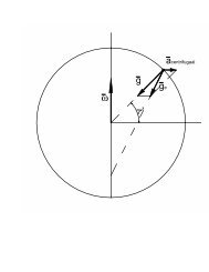
Figure 2: Calculation <strong>of</strong> loss in ground surface<br />
7
Chapter 2: Drive unit<br />
The area <strong>of</strong> <strong>the</strong> partial circle shown in figure 2 is given by:<br />
S partial circle<br />
= r2 . θ<br />
2<br />
(2.2)<br />
With θ given by:<br />
θ = 2. sin −1 ( D<br />
2. r ) (2.3)<br />
The area <strong>of</strong> <strong>the</strong> triangle shown in figure 2 is given by:<br />
S rectangle<br />
= D 2 . r² − D²<br />
4<br />
(2.4)<br />
The loss in surface caused by <strong>the</strong> four wheels is given by:<br />
4. S partial circle − S rectangle (2.5)<br />
In terms <strong>of</strong> percentage, <strong>the</strong> loss in surface becomes:<br />
4.<br />
r 2 . θ<br />
2 − D 2 . r 2 − D2<br />
4<br />
π. r²<br />
.100% (2.6)<br />
The loss <strong>of</strong> ground surface caused by an increasing diameter <strong>of</strong> <strong>the</strong> wheel is given in<br />
figure 3.<br />
8
Loss (%)<br />
Chapter 2: Drive unit<br />
40<br />
Loss in ground surface<br />
36<br />
32<br />
28<br />
24<br />
20<br />
16<br />
12<br />
8<br />
4<br />
0<br />
10 20 30 40 50 60 70 80 90 100 110 120 127<br />
Diameter wheel (mm)<br />
Figure 3: Loss in ground surface <strong>of</strong> <strong>the</strong> robot compared to wheel diameter<br />
The loss <strong>of</strong> space caused by a wheel with diameter between 50 and 70 mm varies<br />
from 1,86% to 5,23%. A loss <strong>of</strong> 6% is equal to a rectangle with dimensions 45x33mm<br />
on <strong>the</strong> ground surface or is approximately <strong>the</strong> coverage <strong>of</strong> a Maxon EC 45 motor<br />
(see later). This loss is assumed acceptable. Because <strong>the</strong> calculation does not<br />
include <strong>the</strong> thickness <strong>of</strong> <strong>the</strong> wheels, a slightly smaller diameter should be selected.<br />
From this, it can be concluded that a diameter <strong>of</strong> 60 mm is a good option in this<br />
application.<br />
9
Chapter 2: Drive unit<br />
2.2.3 Concepts <strong>of</strong> construction<br />
There are many options to achieve an omnidirectional drive <strong>for</strong> <strong>the</strong> robot. In this<br />
paragraph, <strong>the</strong>se options are summarized.<br />
2.2.3.1 Purchase a ready to use wheel<br />
These wheels are already tested. A good working <strong>of</strong> <strong>the</strong>se wheels is guaranteed.<br />
The friction <strong>of</strong> <strong>the</strong> tangential wheels is limited.<br />
There are also some disadvantages. The wheels are not custom made <strong>for</strong> this<br />
application. Also it isn’t an innovative implementation <strong>for</strong> this application.<br />
Figure 4: Rotacaster omniwheel<br />
2.2.3.2 <strong>Small</strong> wheels design<br />
This design is commonly used in most robots <strong>for</strong> <strong>the</strong> RoboCup <strong>Small</strong> <strong>Size</strong> league. It is<br />
a proven concept and can be custom made <strong>for</strong> <strong>the</strong> robot.<br />
Again, it is not an innovative design anymore. The surface on <strong>the</strong> contour covered<br />
by <strong>the</strong> wheels is 25% which is relatively low.<br />
10
Chapter 2: Drive unit<br />
Figure 5: Omniwheel-design by Parsian team[15]<br />
Some experiments were executed by KIKS-team [10]. They experimented with<br />
different widths <strong>of</strong> tangential wheels.<br />
(a) with single ring tires<br />
(b) with double ring tires<br />
(c) with thick rubber ring tires<br />
(d) with thick silicone rubber ring tires<br />
Figure 6: Kiks research[10]: Various types <strong>of</strong> small wheels design<br />
11
Chapter 2: Drive unit<br />
Various design types can be used. <strong>Design</strong> (a) has a low wheel to contour surface<br />
ratio. This means that <strong>the</strong> robot will bounce a lot when driving. Using design type<br />
(d), <strong>the</strong> bouncing <strong>of</strong> <strong>the</strong> robot can be reduced because <strong>the</strong> wheel to contour surface<br />
ratio is much higher in this case.<br />
Figure 7:Kiks research[10]: Average time to reach 1m/s from static condition <strong>for</strong> <strong>the</strong> robot<br />
Figure 7 shows <strong>the</strong> average time to reach 1m/s from static condition <strong>for</strong> <strong>the</strong><br />
different wheels. It is clear that wheel design (a) is <strong>the</strong> best option when choosing<br />
<strong>for</strong> this type <strong>of</strong> design. The KIKS team has no explanation why type (a) is better than<br />
o<strong>the</strong>r designs while accelerating. A better acceleration means that type (a) has<br />
better grip (more efficient power transmission) and/or lower weight because F=a.m.<br />
This remark should be tested when a design is made <strong>for</strong> this application.<br />
12
Chapter 2: Drive unit<br />
2.2.3.3 Concept by <strong>the</strong> Korea University<br />
Figure 8: Omniwheel-design by Korea University [27]<br />
This concept has been developed by <strong>the</strong> Korea University [27]. It has a wheel<br />
surface to contour ratio <strong>of</strong> 100%.<br />
The resistance to contamination is poor. Because <strong>the</strong> robot will drive on a carpet<br />
surface, <strong>the</strong> danger exists that tiny particles will get stuck in <strong>the</strong> space between <strong>the</strong><br />
tangential wheels.<br />
It is very hard to construct <strong>the</strong>se wheels especially when <strong>the</strong> diameter decreases.<br />
For this reason, this concept isn’t suited <strong>for</strong> this application.<br />
13
Chapter 2: Drive unit<br />
2.2.4 Final design<br />
Figure 9: New omniwheel-design<br />
This concept is a combination <strong>of</strong> concept 2 and 3. It uses slightly larger tangential<br />
wheels with a pr<strong>of</strong>ile according to <strong>the</strong> contour <strong>of</strong> <strong>the</strong> wheel. The wheel surface to<br />
contour ratio can be increased to 52%.<br />
This concept hasn’t been proven yet but can be constructed with a small diameter.<br />
The omniwheels exist <strong>of</strong> two disks with grooves. In <strong>the</strong>se grooves, pieces are placed<br />
to hold <strong>the</strong> tangential wheel axles. The wheels are than mounted on a bush. One<br />
bush has a hole through it and <strong>the</strong> o<strong>the</strong>r is threaded inside. These bushes are than<br />
bolted toge<strong>the</strong>r with a small bolt.<br />
The center disk has to be designed in two pieces. O<strong>the</strong>rwise, <strong>the</strong> whole structure<br />
can’t be mounted toge<strong>the</strong>r.<br />
14
Chapter 2: Drive unit<br />
2.3 Driving Motors<br />
The choice <strong>of</strong> <strong>the</strong> motors depends on <strong>the</strong> available space and required propulsion<br />
<strong>for</strong>ce. In <strong>the</strong> RoboCup <strong>Small</strong> <strong>Size</strong> <strong>League</strong>, large accelerations are needed to keep up<br />
with <strong>the</strong> o<strong>the</strong>r competing robots. It seems best to choose motors, similar to <strong>the</strong><br />
motors <strong>of</strong> o<strong>the</strong>r teams to achieve a comparable acceleration. Most teams are using<br />
a brushless type <strong>of</strong> motor because <strong>the</strong>se don’t take a lot <strong>of</strong> space according to <strong>the</strong>ir<br />
power. A motor with following parameters was chosen.<br />
- Maxon EC45 flat brushless motor<br />
- Diameter: 45 mm<br />
- Power: 30 Watt<br />
- Supply voltage: 12V<br />
- Starting current: 10A<br />
- Nominal current: 2.8 A<br />
- Stall torque: 255 mNm<br />
- Nominal torque: 59 mNm<br />
- Weight: 88 gr<br />
Figure 10: Maxon EC 45, 30Watt motor<br />
15
Chapter 2: Drive unit<br />
2.4 Transmission unit<br />
2.4.1 General<br />
The power from <strong>the</strong> motors has to be transferred to <strong>the</strong> wheels. This can be<br />
achieved by directly connecting <strong>the</strong> motor to <strong>the</strong> wheels. In this case, <strong>the</strong> wheels<br />
have a diameter <strong>of</strong> 60mm and <strong>the</strong> motor a diameter <strong>of</strong> 45mm. With a direct<br />
connection, this leaves 7mm <strong>of</strong> ground clearance, which isn’t much. Also, <strong>the</strong> space<br />
in <strong>the</strong> center <strong>of</strong> <strong>the</strong> robot isn’t used optimal with a direct connection. By using a<br />
transmission system, more space at <strong>the</strong> front <strong>of</strong> <strong>the</strong> robot can be made available <strong>for</strong><br />
o<strong>the</strong>r components by placing <strong>the</strong> motors towards <strong>the</strong> back <strong>of</strong> <strong>the</strong> robot.<br />
A second, and more important, reason <strong>for</strong> <strong>the</strong> use <strong>of</strong> a transmission system is <strong>the</strong><br />
reduction <strong>of</strong> motor speed. The motor has a no load speed <strong>of</strong> 4700 rpm which is very<br />
high <strong>for</strong> this application. The wheels have a diameter <strong>of</strong> 60mm thus <strong>the</strong> maximum<br />
speed <strong>of</strong> <strong>the</strong> robot would be 15 m/s or 54 km/h with a direct connection. A<br />
transmission system reduces <strong>the</strong> maximum speed while increasing <strong>the</strong> maximum<br />
torque on <strong>the</strong> wheels. This will have a positive influence on <strong>the</strong> acceleration <strong>of</strong> <strong>the</strong><br />
robot. A transmission system is <strong>the</strong>re<strong>for</strong>e a choice between maximum velocity and<br />
maximum acceleration.<br />
The gear ratio used by competing RoboCup teams vary from 3:1 to 5:1. Most <strong>of</strong><br />
<strong>the</strong>m have slightly smaller wheels. There<strong>for</strong>e, <strong>the</strong> gear ratio in this application<br />
should be at <strong>the</strong> higher side <strong>of</strong> <strong>the</strong> interval to have a similar velocity and<br />
acceleration.<br />
There is not much in<strong>for</strong>mation about <strong>the</strong> optimal gear ratio. Some teams [8] are<br />
now transferring to a 50W and lower gear ratio to have more velocity with <strong>the</strong> same<br />
acceleration. It seems best to consider this remark and choose a higher velocity<br />
than o<strong>the</strong>r competing teams.<br />
In <strong>the</strong> next paragraphs, different types <strong>of</strong> transmission systems are discussed.<br />
16
Chapter 2: Drive unit<br />
2.4.2 Spur gear<br />
In table1 it can be seen that all teams use a transmission system with spur gears.<br />
This seems like <strong>the</strong> most obvious choice as a transmission system. These spur gears<br />
don’t skid, which makes <strong>the</strong> control <strong>of</strong> <strong>the</strong> robot less difficult. When skid occurs, <strong>the</strong><br />
control algorithm can’t <strong>for</strong>ecast <strong>the</strong> location <strong>of</strong> <strong>the</strong> robot anymore, because <strong>the</strong><br />
encoders are mounted on <strong>the</strong> motors instead <strong>of</strong> on <strong>the</strong> wheels. There<strong>for</strong>e, this<br />
transmission system is more reliable than o<strong>the</strong>r systems. For high gear ratio’s, an<br />
internal spur gear can be used to reduce <strong>the</strong> required amount <strong>of</strong> space.<br />
2.4.3 Belt transmission<br />
Ano<strong>the</strong>r system <strong>of</strong> transmission is a belt and pulley system. These are less reliable<br />
because <strong>the</strong>y can skid. As said in previous paragraph, this makes a good control <strong>of</strong><br />
<strong>the</strong> robot difficult. The flexibility <strong>of</strong> this system is an advantage. The pulley’s can be<br />
produced using rapid prototyping. The belts can be made from a slightly elastic<br />
material which is available on a roll. The two ends <strong>of</strong> <strong>the</strong> belt can <strong>the</strong>n be melted<br />
toge<strong>the</strong>r. There<strong>for</strong>e, each desired gear ratio can easily be achieved.<br />
2.4.4 Final design<br />
Be<strong>for</strong>e starting <strong>the</strong> design <strong>of</strong> <strong>the</strong> transmission system, some comments have to be<br />
made. The batteries used in <strong>the</strong> robot should be built in as low as possible to lower<br />
<strong>the</strong> center <strong>of</strong> gravity. Because <strong>the</strong> transmission units are at an angle relative to each<br />
o<strong>the</strong>r, a small space is created between <strong>the</strong>se units. This space can be used to<br />
mount batteries to optimize <strong>the</strong> use <strong>of</strong> space. Figure 11 shows <strong>the</strong> integration <strong>of</strong> <strong>the</strong><br />
batteries in <strong>the</strong> transmission unit. The batteries have a blue color in this figure.<br />
17
Chapter 2: Drive unit<br />
Figure 11: Structural design <strong>of</strong> transmission units<br />
The four transmission units can be designed separately. This has a negative<br />
influence on <strong>the</strong> rigidness <strong>of</strong> <strong>the</strong> robot because <strong>the</strong>y are not connected. To increase<br />
rigidness, <strong>the</strong> units on each side <strong>of</strong> <strong>the</strong> robot should be connected. Two separate<br />
structures which hold two motors, wheels and transmission system are <strong>the</strong>re<strong>for</strong>e<br />
created. By opting <strong>for</strong> two separate structures, more space is available <strong>for</strong> <strong>the</strong><br />
kicking device and dribbler than in case <strong>of</strong> one large structure. Figure 12 and 13<br />
show a close-up <strong>of</strong> <strong>the</strong> transmission structure, one with a spur gear and <strong>the</strong> o<strong>the</strong>r<br />
with a pulley.<br />
18
Chapter 2: Drive unit<br />
Figure 12: Close-up <strong>of</strong> front transmission<br />
unit with spur gears<br />
Figure 13: Close-up <strong>of</strong> rear transmission<br />
unit with pulley<br />
2.5 Experiments<br />
During <strong>the</strong> first tests, it was seen that not all <strong>of</strong> <strong>the</strong> contact points <strong>of</strong> <strong>the</strong> wheels<br />
with <strong>the</strong> ground surface were located in one plane. This causes at least one wheel<br />
to lose some grip. This can cause problems <strong>for</strong> <strong>the</strong> control s<strong>of</strong>tware.<br />
A solution <strong>for</strong> this problem is to suspend <strong>the</strong> wheels like in o<strong>the</strong>r vehicles. The<br />
suspension system could also reduce <strong>the</strong> bouncing <strong>of</strong> <strong>the</strong> robot due to <strong>the</strong> noncircular<br />
wheels.<br />
An experiment was per<strong>for</strong>med to test <strong>the</strong> belt and spur gear transmission. The belt<br />
transmission skids while driving. This isn’t <strong>the</strong> case with <strong>the</strong> spur gear transmission.<br />
There<strong>for</strong>e, it is concluded that <strong>the</strong> spur gear transmission is <strong>the</strong> best option <strong>for</strong> this<br />
application.<br />
19
Chapter 2: Drive unit<br />
2.6 Conclusions<br />
In this chapter, <strong>the</strong> drive unit was discussed. From a comparison between all<br />
competing teams, it can be concluded that almost all teams use four wheels. This<br />
provides extra space along <strong>the</strong> roll axis <strong>of</strong> <strong>the</strong> robot to implement a shooting<br />
system. There<strong>for</strong>e, four wheels are used in this application.<br />
There are several possible designs <strong>for</strong> <strong>the</strong> omni-directional wheels. The competing<br />
teams all use a similar wheel design with small tangential wheels. For this<br />
application, a new concept was developed with larger tangential wheel. There<strong>for</strong>e,<br />
a higher wheels surface to contour ratio is obtained.<br />
The motors used by <strong>the</strong> competing teams have a power rating varying from 30 to 50<br />
Watts. In this application a 30 Watt EC45 Maxon motor is used, which is a<br />
commonly used motor in <strong>the</strong> RoboCup <strong>Small</strong> <strong>Size</strong> competition. This motor powers<br />
<strong>the</strong> wheels via a transmission unit. In this application, two principles <strong>of</strong> transmission<br />
are reviewed. From tests, it is concluded that a spur gear transmission is <strong>the</strong> best<br />
option. This transmission doesn’t skid like <strong>the</strong> belt transmission.<br />
20
Chapter 3: Kicking device<br />
3 Kicking device<br />
3.1 General<br />
There are several designs used by competing RoboCup Teams. The design<br />
parameters <strong>for</strong> a shooting device are <strong>the</strong> following:<br />
- Efficiency<br />
- Cost<br />
- Weight<br />
- Required space<br />
- Time between shots<br />
- Number <strong>of</strong> shots<br />
- Safety<br />
- Variable <strong>for</strong>ce<br />
3.2 State <strong>of</strong> <strong>the</strong> art<br />
Table 3: Comparison between RoboCup teams: Kicking device<br />
Team Device type Ball speed Chip-kick device<br />
(distance in <strong>the</strong> air)<br />
Botania Dragon Knights [1]<br />
Brocks [2]<br />
Solenoid<br />
B-Smart [3]<br />
CMDragons [4] Solenoid 15 m/s 4,5 m<br />
Eagle Knights [5]<br />
Solenoid<br />
ER-Force [6]<br />
Solenoid 8 m/s<br />
(New system)<br />
Field Rangers [7] Solenoid 10 m/s 6 m<br />
Immortals [8]<br />
Solenoid<br />
Khainui [9]<br />
Solenoid<br />
KIKS [10]<br />
Solenoid<br />
21
Chapter 3: Kicking device<br />
KN2C [11]<br />
Solenoid<br />
ODENS [12]<br />
Solenoid<br />
OMID [13] Solenoid 8 m/s<br />
Owaribito [14] Solenoid 10 m/s<br />
Parsian [15] Solenoid 5 m<br />
RFC Cambridge [16]<br />
Solenoid<br />
Robojackets [17]<br />
Solenoid<br />
Robodragons [18]<br />
Solenoid<br />
RoboFEI [19]<br />
Solenoid<br />
RoboFighties [20]<br />
RoboPET [21] Solenoid 10 m/s<br />
Skuba [22] Solenoid 14 m/s 7,5 m<br />
MRL [23]<br />
Solenoid<br />
UBC Thunderbots [24] Solenoid 8 m/s<br />
Plasma-Z [25]<br />
Solenoid<br />
From table 3 it can be concluded that all teams which use a shooting system have<br />
opted <strong>for</strong> a solenoid system. In <strong>the</strong> past, <strong>the</strong> Philips CFT team [28] used a<br />
mechanical spring actuated system. Back <strong>the</strong>n, larger dimensions <strong>of</strong> <strong>the</strong> robot were<br />
allowed. Such a system was easier to implement because <strong>of</strong> <strong>the</strong>se dimensions.<br />
3.3 Types <strong>of</strong> shooting devices<br />
The electrical energy stored in <strong>the</strong> batteries has to be trans<strong>for</strong>med in mechanical<br />
energy to move <strong>the</strong> ball. This can be accomplished in different ways.<br />
3.3.1 Solenoid actuated<br />
In this system, self-inductance is used. A current is send through a coil which<br />
generates a magnetic field. This field can be increased by increasing <strong>the</strong> number <strong>of</strong><br />
windings <strong>of</strong> <strong>the</strong> coil or by increasing <strong>the</strong> current through <strong>the</strong> coil. With this magnetic<br />
field, a ferromagnetic material can be attracted or repulsed.<br />
22
Chapter 3: Kicking device<br />
Most solenoids available in stores are not suitable <strong>for</strong> this application. They work on<br />
low voltage and are very slow. The <strong>for</strong>ce <strong>the</strong>y develop is ra<strong>the</strong>r low. This results in<br />
low ball velocities. In order to kick <strong>the</strong> ball at high velocities, a high voltage solenoid<br />
is required. These aren’t available in stores yet so <strong>the</strong>y have to be built a custom to<br />
<strong>the</strong> application. With <strong>the</strong>se high voltage solenoids, ball speeds <strong>of</strong> up to 10 m/s are<br />
no exception.<br />
The dimensions <strong>of</strong> <strong>the</strong> system depend on <strong>the</strong> design. For this application, typical<br />
values are <strong>the</strong> following [14]:<br />
- A total mass <strong>of</strong> up to 200 gr<br />
- Ball speeds <strong>of</strong> more than 10m/s<br />
- 200 volt circuit<br />
- 3700 µF capacitors<br />
This system is very flexible in terms <strong>of</strong> creating a variable shooting <strong>for</strong>ce. The time<br />
to reload can be kept low. The number <strong>of</strong> shots is only limited by <strong>the</strong> state <strong>of</strong> <strong>the</strong><br />
battery.<br />
The most important disadvantages are <strong>the</strong> safety risks involved in using high<br />
voltage. Also, a lot <strong>of</strong> heat is generated when activating <strong>the</strong> system. This heat has to<br />
be evacuated out <strong>of</strong> <strong>the</strong> robot. Ano<strong>the</strong>r disadvantage is <strong>the</strong> required space <strong>for</strong> <strong>the</strong><br />
capacitors and <strong>the</strong> weight <strong>of</strong> <strong>the</strong> coil.<br />
Most competing teams at present use this system. Many developments are made in<br />
terms <strong>of</strong> reducing <strong>the</strong> weight and increasing <strong>the</strong> power <strong>of</strong> <strong>the</strong> system. This system<br />
has been tested with success by many teams.<br />
3.3.2 Spring actuated<br />
This system is based on <strong>the</strong> storage <strong>of</strong> energy in a spring. It has two major functions.<br />
The first function has <strong>the</strong> task <strong>of</strong> winding <strong>the</strong> spring up. The second function is a<br />
lock/release system to hold <strong>the</strong> plunger in his place while winding up and releasing<br />
<strong>the</strong> spring when needed.<br />
23
Chapter 3: Kicking device<br />
This system is more safe <strong>the</strong>n <strong>the</strong> solenoid system because <strong>the</strong>re is no high voltage<br />
present. With a well designed system, <strong>the</strong> cost and required space can also be<br />
reduced. When friction is reduced, very high efficiency can be achieved because<br />
<strong>the</strong>re is a direct connection from <strong>the</strong> motor to <strong>the</strong> spring. The number <strong>of</strong> shots is<br />
only limited by <strong>the</strong> state <strong>of</strong> <strong>the</strong> batteries.<br />
The major disadvantage is <strong>the</strong> reload time. It takes a powerful motor to reload <strong>the</strong><br />
system in a short time. A variable shooting <strong>for</strong>ce can be achieved but again, it takes<br />
time to set <strong>the</strong> spring at this desired <strong>for</strong>ce.<br />
3.3.3 Pneumatic actuated<br />
In <strong>the</strong> past, a lot <strong>of</strong> <strong>the</strong> teams used a pneumatic actuated system [28]. The air<br />
pressure is retrieved from a large air tank on <strong>the</strong> robot that is pressurized be<strong>for</strong>e<br />
<strong>the</strong> match. Pneumatic cylinders are connected to a solenoid actuated valve which<br />
controls <strong>the</strong> airflow.<br />
A big disadvantage <strong>of</strong> this system is <strong>the</strong> large air tank that has to be built in.<br />
The number <strong>of</strong> shots depends on <strong>the</strong> volume <strong>of</strong> <strong>the</strong> tank and <strong>the</strong> pressure inside <strong>the</strong><br />
tank.<br />
3.3.4 O<strong>the</strong>r<br />
A lot <strong>of</strong> o<strong>the</strong>r systems can be designed <strong>for</strong> <strong>the</strong> purpose <strong>of</strong> shooting <strong>the</strong> ball. Most <strong>of</strong><br />
<strong>the</strong>se systems have several major flaws.<br />
For instance a rack and spur device can be used. This system needs a large motor<br />
with huge power ratings.<br />
24
Chapter 3: Kicking device<br />
3.4 Shooting system model<br />
3.4.1 General<br />
For this application, it was decided to construct a spring actuated shooting device.<br />
To wind <strong>the</strong> spring up, a spindle with nut is used. The nut presses against <strong>the</strong><br />
spring which is <strong>the</strong>reby compressed. A lock and release mechanism holds <strong>the</strong><br />
plunger in place and releases it when needed.<br />
The modeling <strong>of</strong> <strong>the</strong> shooting system will be divided into three parts. A first part is<br />
determining <strong>the</strong> maximum <strong>for</strong>ce <strong>the</strong> motor can deliver. Based on this value, a<br />
spring can be selected in <strong>the</strong> second part. In this part, <strong>the</strong> time needed <strong>for</strong> <strong>the</strong><br />
winding <strong>of</strong> <strong>the</strong> spring is modeled. The third part will determine <strong>the</strong> parameters<br />
needed to model <strong>the</strong> actual shooting process.<br />
3.4.1.1 Force in spindle<br />
The <strong>for</strong>ce that can be generated to compress <strong>the</strong> spring depends on <strong>the</strong> applied<br />
torque on <strong>the</strong> spindle. With following <strong>for</strong>mulas, this can be calculated. [26]<br />
With:<br />
T = F. d 2<br />
2 . tan φ ± ρ′ (4.1)<br />
F<br />
d 2<br />
φ<br />
longitudinal <strong>for</strong>ce in <strong>the</strong> axis<br />
pitch diameter <strong>of</strong> <strong>the</strong> screw thread<br />
lead-angle <strong>of</strong> <strong>the</strong> screw thread<br />
ρ’ screw thread friction angle.<br />
+ <strong>for</strong> tightening<br />
- <strong>for</strong> releasing<br />
Re<strong>for</strong>ming <strong>for</strong>mula 4.1 with <strong>the</strong> <strong>for</strong>ce on <strong>the</strong> right hand side:<br />
T. 2<br />
F =<br />
d 2 . tan φ ± ρ ′<br />
(4.2)<br />
25
Chapter 3: Kicking device<br />
3.4.1.2 Compression process<br />
Using <strong>the</strong> stall torque <strong>of</strong> <strong>the</strong> motor in <strong>for</strong>mula 4.2, a spring can be selected to use in<br />
<strong>the</strong> application. The parameters <strong>of</strong> <strong>the</strong> spring are <strong>the</strong> following:<br />
- F spring = Force in te spring wen compressed<br />
- l f = Free lengt<br />
- lc = Compressed lengt<br />
With <strong>the</strong>se parameters, <strong>the</strong> compression parameters can be calculated. These<br />
parameters are <strong>the</strong> <strong>for</strong>ce in <strong>the</strong> spring while compressing, <strong>the</strong> rotation speed <strong>of</strong> <strong>the</strong><br />
motor and <strong>the</strong> compression time.<br />
A <strong>for</strong>ce function can be found according to <strong>the</strong> compressed length (x) <strong>of</strong> <strong>the</strong> spring:<br />
F spring = k. x (4.3)<br />
From this <strong>for</strong>ce function, a rotation speed function can be derived. The relation<br />
between <strong>the</strong> motor torque and rotation speed according to <strong>the</strong> maxon datasheet<br />
[31] is given by:<br />
n = n 0 − n 0<br />
M H<br />
. M (4.4)<br />
With:<br />
- n 0 : No load rotation speed<br />
- M H : Stall torque<br />
- n: Rotation speed <strong>of</strong> <strong>the</strong> motor<br />
- M: Torque <strong>of</strong> <strong>the</strong> motor<br />
26
Chapter 3: Kicking device<br />
The rotation speed <strong>of</strong> <strong>the</strong> motor can be expressed as a function <strong>of</strong> <strong>the</strong> spring<br />
compression ‘x’ using <strong>for</strong>mula 4.2, 4.3 and 4.4. Rotation speed is expressed in<br />
revolutions per second.<br />
n = n 0 − x. k. d 2. n 0 . tanφ ± ρ ′<br />
2. M H<br />
(4.5)<br />
With this rotation speed function, <strong>the</strong> time needed to wind <strong>the</strong> spring up to a<br />
compressed length <strong>of</strong> ‘r’ can be calculated. When <strong>the</strong> spring is compressed an<br />
infinite part dx with rotation speed n, <strong>the</strong> time needed to do this is given by:<br />
dt = dx<br />
n. a<br />
(4.6)<br />
The total time needed to compress <strong>the</strong> spring to length ‘r’ can be calculated.<br />
t =<br />
r<br />
dx<br />
0<br />
n. a<br />
(4.7)<br />
This results in:<br />
t =<br />
−2. M H<br />
k. d 2 . tan φ ± ρ ′ . n 0 . a . ln 1 − r. k. d 2. tan φ ± ρ ′<br />
2. M H<br />
(4.8)<br />
27
Chapter 3: Kicking device<br />
3.4.1.3 Releasing process<br />
In this paragraph, <strong>the</strong> releasing process is discussed. It is assumed that <strong>the</strong> process<br />
will take place in three phases. In <strong>the</strong> first phase, <strong>the</strong> plunger will move towards <strong>the</strong><br />
ball without touching it. The second phase is <strong>the</strong> moment <strong>of</strong> impact between <strong>the</strong><br />
plunger and <strong>the</strong> ball. At this time, <strong>the</strong> preservation <strong>of</strong> impulse law can be used. For<br />
<strong>the</strong> third phase, it is assumed that <strong>the</strong> ball and plunger will move toge<strong>the</strong>r.<br />
There<strong>for</strong>e, <strong>the</strong> spring accelerates <strong>the</strong> combined system <strong>of</strong> plunger and ball. In <strong>the</strong><br />
actual system, it is possible that <strong>the</strong> ball will move faster than <strong>the</strong> plunger. The<br />
velocity <strong>of</strong> <strong>the</strong> ball will be greater than <strong>the</strong> calculated one in this case. There<strong>for</strong>e,<br />
<strong>the</strong> model gives a worst case scenario.<br />
At <strong>the</strong> <strong>of</strong> <strong>the</strong> third phase, <strong>the</strong> shooting velocity <strong>of</strong> <strong>the</strong> ball is reached.<br />
Figure 14: Shooting system release process parameters<br />
28
Chapter 3: Kicking device<br />
The following parameters will be used to per<strong>for</strong>m <strong>the</strong> calculation:<br />
- F 0 = Spring <strong>for</strong>ce be<strong>for</strong>e releasing= k.l 0<br />
- s = total stroke lengt<br />
- x = position <strong>of</strong> te plunger<br />
- F = <strong>for</strong>ce in te spring at position x<br />
- k = spring stiffness<br />
- α = plunger <strong>of</strong>fset<br />
A. Only plunger moves<br />
To make <strong>the</strong> results more logic, <strong>the</strong> origin <strong>of</strong> <strong>the</strong> x-axis is changed. It is now<br />
assumed that x is zero at <strong>the</strong> start <strong>of</strong> <strong>the</strong> releasing-process. The <strong>for</strong>ce in <strong>the</strong> spring is<br />
function <strong>of</strong> x:<br />
F = k. l 0 − x = F 0 − k. x (4.9)<br />
The acceleration is given by:<br />
a =<br />
F<br />
m plunger<br />
= F 0 − k. x<br />
m plunger<br />
(4.10)<br />
In order to solve this problem, a differential equation has to be solved:<br />
m plunger . x + k. x = F 0 (4.11)<br />
The solution <strong>of</strong> this equation has following <strong>for</strong>m:<br />
With:<br />
x t = Acos ωt + Bsin ωt + C (4.12)<br />
ω² =<br />
k<br />
m plunger<br />
(4.13)<br />
29
Chapter 3: Kicking device<br />
The boundary conditions are:<br />
x 0 = 0<br />
v 0 = 0<br />
a 0 =<br />
F 0<br />
m plunger<br />
Filling in <strong>the</strong>se boundary conditions leads to values <strong>of</strong> A,B,C:<br />
x t = F 0<br />
k<br />
. 1 − cos ωt (4.14)<br />
v t = F 0<br />
. ω. sin ωt (4.15)<br />
k<br />
F 0<br />
a t = . cos ωt (4.16)<br />
m plunger<br />
B. Impact<br />
The value <strong>of</strong> x where impact occurs is noted as ‘α’. From <strong>for</strong>mula 4.20, <strong>the</strong> time t1<br />
<strong>of</strong> impact can be determined:<br />
α = F 0<br />
k . 1 − cos ωt 1 (4.17)<br />
cos ωt 1 = 1 −<br />
ω. t 1 = cos −1 ( 1 −<br />
k. α<br />
F 0<br />
(4.18)<br />
k. α<br />
F 0<br />
) (4.19)<br />
With <strong>for</strong>mula 4.23, <strong>the</strong> velocity right be<strong>for</strong>e impact becomes:<br />
v t1 = F 0<br />
k . ω. sin k. α<br />
cos−1 ( 1 − ) (4.20)<br />
F 0<br />
v t1 = F 2<br />
0<br />
k . ω. k. α<br />
1 − 1 −<br />
F 0<br />
(4.21)<br />
v t1 =<br />
2. α. F 0 − k. α²<br />
m plunger<br />
(4.22)<br />
30
Chapter 3: Kicking device<br />
At <strong>the</strong> moment <strong>of</strong> impact, <strong>the</strong> conservation <strong>of</strong> impulse law can be used to<br />
determine <strong>the</strong> velocity after <strong>the</strong> impact.<br />
m plunger v plunger ,t1 + m bal v bal ,t1 = (m plunger + m ball ). v t2 (4.23)<br />
Assuming that <strong>the</strong> velocity <strong>of</strong> <strong>the</strong> ball is zero be<strong>for</strong>e impact:<br />
v t2 = m plunger v plunger ,t1<br />
m plunger + m ball<br />
( 4.24)<br />
v t2 =<br />
m plunger<br />
2. α. F 0 − k. α²<br />
m plunger<br />
m plunger + m ball<br />
(4.25)<br />
C. Accelerating plunger and ball<br />
This calculation is similar to those made in section A. The mass becomes <strong>the</strong><br />
combined mass <strong>of</strong> plunger and ball. Only <strong>the</strong> start conditions <strong>of</strong> <strong>the</strong> differential<br />
equation change. Variable ‘x’ is equal to α at <strong>the</strong> start. The velocity is equal to v t2 at<br />
<strong>the</strong> start and <strong>the</strong> acceleration at <strong>the</strong> start becomes:<br />
F 0 − k. α<br />
m total<br />
x t = α − F 0<br />
k<br />
. cos ωt + v t2<br />
ω . sin ωt + F 0<br />
k<br />
(4.26)<br />
v t = ω. F 0<br />
k − α . sin ωt + v t2. cos(ωt) (4.27)<br />
a t = ω 2 . F 0<br />
k − α . cos ωt − v t2. ω. sin(ωt) (4.28)<br />
31
Chapter 3: Kicking device<br />
3.4.2 Application note<br />
In this paragraph, <strong>the</strong> ma<strong>the</strong>matical model is applied on <strong>the</strong> shooting system <strong>of</strong> <strong>the</strong><br />
robot. For this application, following components will be used.<br />
Table 4: Shooting system components<br />
Motor: Steel Spindle: Plunger: Spring:<br />
P=2.5 watt M3 mass=140gr F=300N<br />
n 0: 11400 a=0.5mm lf=50 mm<br />
M H : 8,52mNm l=30mm lc=30 mm<br />
Gear ratio: 1/17<br />
d2=2.675mm<br />
φ=3. 41°<br />
ρ’=12°<br />
The motor that is used was already available and will be used <strong>for</strong> testing purposes.<br />
When this motor is proven insufficient, ano<strong>the</strong>r one can be mounted.<br />
The diameter <strong>of</strong> <strong>the</strong> spindle is kept as low as possible because it acts as a sort <strong>of</strong><br />
reduction <strong>for</strong> <strong>the</strong> motor. Using <strong>the</strong> spindle as a reduction results in a more compact<br />
design.<br />
3.4.2.1 Spring selection<br />
In order to select a spring, <strong>the</strong> maximum achievable <strong>for</strong>ce has to be determined:<br />
F max =<br />
M H . 2<br />
= 392 N (4.29)<br />
d 2 . tan φ ± ρ<br />
′<br />
When this maximum <strong>for</strong>ce is used to select an imaginary spring, <strong>the</strong> time to wind<br />
<strong>the</strong> spring up can be calculated using <strong>for</strong>mula 4.8. The spring stiffness ‘k’ is given by:<br />
32
Force (N)<br />
Chapter 3: Kicking device<br />
k = F max<br />
l<br />
=<br />
392 N<br />
20 mm = 19644 N m<br />
With l: <strong>the</strong> length <strong>of</strong> <strong>the</strong> spring which is determined by <strong>the</strong> shooting system design.<br />
The result is shown in figure 14.<br />
400<br />
Compression process<br />
350<br />
300<br />
250<br />
200<br />
150<br />
100<br />
50<br />
0<br />
0 5 10 15 20 25<br />
time (s)<br />
Figure 15: Compressed spring length as function <strong>of</strong> <strong>the</strong> time<br />
When a spring is selected with a compressed <strong>for</strong>ce close to <strong>the</strong> maximum<br />
achievable <strong>for</strong>ce <strong>of</strong> <strong>the</strong> motor, <strong>the</strong> time to compress <strong>the</strong> spring will increase rapidly.<br />
It is seen in figure 15 that a <strong>for</strong>ce <strong>of</strong> 350 N is reached, <strong>the</strong> time to compress <strong>the</strong><br />
spring fur<strong>the</strong>r increases rapidly.<br />
In this application note, a maximum <strong>for</strong>ce <strong>of</strong> 300 N is used to reduce <strong>the</strong><br />
compression time. This is a difference <strong>of</strong> 24% relative to <strong>the</strong> maximum <strong>for</strong>ce. The<br />
parameters <strong>of</strong> <strong>the</strong> spring are <strong>the</strong> following:<br />
- The stiffness becomes 17700 N/m.<br />
- The difference between free length and compressed length is 20 mm.<br />
33
Time (s)<br />
Chapter 3: Kicking device<br />
3.4.2.2 Compression process<br />
The time to wind this spring up can be determined using <strong>for</strong>mula 4.8 :<br />
t =<br />
−2. M H<br />
k. d 2 . tan φ ± ρ ′ . n 0 . a . ln 1 − r. k. d 2. tan φ ± ρ ′<br />
= 6,8 s<br />
2. M H<br />
7<br />
Compression process <strong>of</strong> selected spring<br />
6<br />
5<br />
4<br />
3<br />
2<br />
1<br />
0<br />
0 2 4 6 8 10 12 14 16 18 20<br />
Compression spring length (mm)<br />
Figure 16: Compression time with selected spring<br />
In figure 16, <strong>the</strong> time to compress <strong>the</strong> spring is given in function <strong>of</strong> <strong>the</strong> compressed<br />
length. The compressed length is proportional to <strong>the</strong> <strong>for</strong>ce. There<strong>for</strong>e, <strong>the</strong> graphic<br />
which represents <strong>the</strong> time in function <strong>of</strong> <strong>the</strong> <strong>for</strong>ce is similar to figure 16.<br />
The time needed to wind <strong>the</strong> spring up is relatively high. A reduction <strong>of</strong> this time<br />
can be achieved by pre-compressing <strong>the</strong> spring. In this case, it has to be considered<br />
that <strong>the</strong> <strong>for</strong>ce in <strong>the</strong> spring cannot start from zero. This implicates that <strong>the</strong> shooting<br />
system is not fully variable but has a minimum shooting velocity. In a later stage <strong>of</strong><br />
34
speed (m/s)<br />
Chapter 3: Kicking device<br />
<strong>the</strong> project, a more powerful motor should allow to reduce this time. The selected<br />
components will be used <strong>for</strong> testing purposes and to verify <strong>the</strong> ma<strong>the</strong>matical<br />
model.<br />
3.4.2.3 Releasing process<br />
In this paragraph, <strong>the</strong> releasing process is discussed. The <strong>for</strong>ce at <strong>the</strong> start <strong>of</strong> <strong>the</strong><br />
release is set at <strong>the</strong> maximum compressed <strong>for</strong>ce <strong>of</strong> <strong>the</strong> spring.<br />
8<br />
Speed <strong>of</strong> plunger and ball in function <strong>of</strong> <strong>the</strong> time<br />
7<br />
6<br />
5<br />
4<br />
plunger<br />
ball<br />
3<br />
2<br />
1<br />
0<br />
0 1 2 3 4 5 6<br />
time (ms)<br />
Figure 17: Plunger and ball speed as function <strong>of</strong> time<br />
In figure 17, <strong>the</strong> plunger velocity is given as function <strong>of</strong> <strong>the</strong> time. At approximately 2<br />
ms, <strong>the</strong> speed drops because <strong>of</strong> <strong>the</strong> impact with <strong>the</strong> ball. From that time, <strong>the</strong><br />
plunger speed is equal to <strong>the</strong> ball speed. The final speed <strong>of</strong> <strong>the</strong> ball is equal to 7m/s.<br />
This is lower than <strong>the</strong> goal <strong>of</strong> 10 m/s. Again, this setup will be used <strong>for</strong> testing<br />
purposes. When a good design is created, a more powerful motor can be mounted.<br />
35
acceleration (m/s²)<br />
speed (m/s)<br />
Chapter 3: Kicking device<br />
8<br />
Plunger velocity as function <strong>of</strong> <strong>the</strong> spring length<br />
7<br />
6<br />
5<br />
4<br />
3<br />
2<br />
1<br />
0<br />
0 5 10 15 20 25<br />
spring length (mm)<br />
Figure 18: Plunger velocity as function <strong>of</strong> <strong>the</strong> spring length<br />
2200<br />
Plunger acceleration as function <strong>of</strong> <strong>the</strong> spring lengh<br />
2000<br />
1800<br />
1600<br />
1400<br />
1200<br />
1000<br />
0 5 10 15 20 25<br />
spring length (mm)<br />
Figure 19: Plunger acceleration as function <strong>of</strong> <strong>the</strong> spring length<br />
36
all end velocity (m/s)<br />
Chapter 3: Kicking device<br />
3.4.2.4 Optimizing plunger weight<br />
By changing <strong>the</strong> plunger’s weight, a higher ball velocity can be obtained. Figure 20<br />
shows <strong>the</strong> effect <strong>of</strong> <strong>the</strong> plunger mass on <strong>the</strong> ball velocity. The maximum <strong>for</strong>ce <strong>of</strong> <strong>the</strong><br />
spring was set at 300N.<br />
12<br />
Effect <strong>of</strong> <strong>the</strong> plunger mass on <strong>the</strong> ball velocity<br />
11<br />
10<br />
9<br />
8<br />
7<br />
6<br />
0 20 40 60 80 100 120 140 160 180 200<br />
plunger mass (gram)<br />
Figure 20: Ball velocity as function <strong>of</strong> plunger mass<br />
From this graph, it can be concluded that <strong>the</strong> mass <strong>of</strong> <strong>the</strong> plunger should be kept as<br />
low as possible. A velocity <strong>of</strong> 10m/s can be achieved with a plunger mass lower as<br />
40 gram.<br />
37
Ball end velocity (m/s)<br />
Chapter 3: Kicking device<br />
3.4.2.5 Effect <strong>of</strong> <strong>the</strong> plunger <strong>of</strong>fset α<br />
In this paragraph, <strong>the</strong> effect <strong>of</strong> <strong>the</strong> plunger <strong>of</strong>fset (α) relative to <strong>the</strong> ball is discussed.<br />
This <strong>of</strong>fset is <strong>the</strong> distance between <strong>the</strong> ball and <strong>the</strong> plunger at <strong>the</strong> start <strong>of</strong> <strong>the</strong><br />
releasing process.<br />
Effect <strong>of</strong> <strong>the</strong> plunger <strong>of</strong>fset relative to <strong>the</strong> ball<br />
3<br />
2.5<br />
2<br />
1.5<br />
1<br />
0.5<br />
0<br />
1 2 3 4 5 6 7 8 9 10<br />
Plunger <strong>of</strong>fset (mm)<br />
Figure 21: Effect <strong>of</strong> <strong>the</strong> plunger <strong>of</strong>fset<br />
Figure 21 shows that <strong>the</strong>re is an effect <strong>of</strong> <strong>the</strong> plunger <strong>of</strong>fset on <strong>the</strong> end velocity <strong>of</strong><br />
<strong>the</strong> ball. It seems best to keep <strong>the</strong> <strong>of</strong>fset as low as possible.<br />
38
Chapter 3: Kicking device<br />
3.5 First construction<br />
Figure 22: First shooting system, general overview<br />
In this paragraph, a first design concept is discussed. The DC motor is mounted<br />
directly onto <strong>the</strong> spindle (see figure 23). In this case, <strong>the</strong> spindle has a diameter <strong>of</strong><br />
3mm in order to achieve a large reduction ratio between <strong>the</strong> motor speed and<br />
linear displacement <strong>of</strong> <strong>the</strong> spring. The spindle is threaded with a triangular M3<br />
screw thread.<br />
Figure 23: First shooting system: view on <strong>the</strong> spindle<br />
39
Chapter 3: Kicking device<br />
A nut is mounted on <strong>the</strong> spindle to achieve <strong>the</strong> linear displacement (see figure 24).<br />
The nut has a specific pr<strong>of</strong>ile which fits into a guidance bush. The pr<strong>of</strong>ile makes sure<br />
that <strong>the</strong> nut cannot turn in <strong>the</strong> guidance bush. O<strong>the</strong>rwise, <strong>the</strong>re would be no linear<br />
displacement.<br />
Figure 24: First shooting system: close-up on <strong>the</strong> displacement nut (left) and guidance bush (right)<br />
The spring is mounted between <strong>the</strong> displacement nut and <strong>the</strong> plunger. To hold <strong>the</strong><br />
spring in place, <strong>the</strong> spindle is made long enough so that <strong>the</strong> plunger will never lose<br />
contact with <strong>the</strong> spindle. There<strong>for</strong>e, <strong>the</strong> spring can never get <strong>of</strong>f <strong>the</strong> plunger.<br />
To hold <strong>the</strong> plunger in place while winding <strong>the</strong> spring up, a lock/release mechanism<br />
is made (see figure 25). This is achieved by cutting <strong>the</strong> pr<strong>of</strong>ile <strong>of</strong> <strong>the</strong> plunger out <strong>of</strong> a<br />
ring. When <strong>the</strong> ring is turned relatively to <strong>the</strong> plunger, <strong>the</strong> pr<strong>of</strong>ile will also be<br />
turned. There<strong>for</strong>e, <strong>the</strong> plunger can only get through <strong>the</strong> ring when <strong>the</strong> pr<strong>of</strong>ile is<br />
exactly in <strong>the</strong> right position. A stepper motor will actuate this ring to release <strong>the</strong><br />
plunger.<br />
40
Chapter 3: Kicking device<br />
Figure 25: First shooting system, close-up on <strong>the</strong> release ring<br />
3.6 Second construction<br />
Figure 26: Second shooting system, general overview<br />
In this first design, a lightweight plunger is used. Because <strong>the</strong> ma<strong>the</strong>matical model<br />
wasn’t finished when <strong>the</strong> design was made, a second construction was built with a<br />
41
Chapter 3: Kicking device<br />
heavier plunger to test <strong>the</strong> effects. The working principle is <strong>the</strong> same, only <strong>the</strong><br />
dimensions were enlarged. The large plunger is more difficult to place in <strong>the</strong> limited<br />
amount <strong>of</strong> space. There<strong>for</strong>e, <strong>the</strong> winding mechanism is fit into <strong>the</strong> plunger to save<br />
space. This is seen in figure 27, where <strong>the</strong> lid is taken <strong>of</strong> <strong>the</strong> plunger and <strong>the</strong>re<strong>for</strong>e<br />
<strong>the</strong> displacement nut is exposed.<br />
Figure 27: Second shooting system, view on <strong>the</strong> plunger and spindle<br />
In <strong>the</strong> first design, it wasn’t considered that a large axial <strong>for</strong>ce is generated in <strong>the</strong><br />
spindle. All this <strong>for</strong>ce had to be endured by <strong>the</strong> bearings in <strong>the</strong> motor. When a large<br />
<strong>for</strong>ce is applied, this isn’t ideal <strong>for</strong> <strong>the</strong> endurance <strong>of</strong> <strong>the</strong> motor. In this second<br />
construction, <strong>the</strong> axial <strong>for</strong>ce is handled by a footstep bearing which presses against<br />
<strong>the</strong> outer body. This is seen in figure 27 and in figure 28, at <strong>the</strong> end <strong>of</strong> <strong>the</strong> guidance<br />
bush.<br />
Figure 28: Second shooting system, close-up on <strong>the</strong> guidance bush and footstep bearing<br />
42
Chapter 3: Kicking device<br />
The actuation <strong>of</strong> <strong>the</strong> release ring needs a sufficient amount <strong>of</strong> torque. The stepper<br />
motor used in <strong>the</strong> first design cannot deliver this amount. In this design, a<br />
servomotor is used to increase <strong>the</strong> amount <strong>of</strong> torque and to achieve a more<br />
accurate positioning <strong>of</strong> <strong>the</strong> release ring. This is seen in figure 29.<br />
Figure 29: Second shooting system, view on <strong>the</strong> release ring and servomotor<br />
43
Chapter 3: Kicking device<br />
3.7 Experiments<br />
In order to test <strong>the</strong> ma<strong>the</strong>matical model, some experiments are per<strong>for</strong>med. In this<br />
paragraph, <strong>the</strong>se experiments are discussed.<br />
Be<strong>for</strong>e starting <strong>the</strong> experiments, some comments have to be made. Due to<br />
adaptations in <strong>the</strong> design <strong>of</strong> <strong>the</strong> shooting systems, <strong>the</strong> values from paragraph 3.4.2<br />
can’t be used to compare <strong>the</strong> experiments. Table 5 gives <strong>the</strong> adapted values from<br />
<strong>the</strong> ma<strong>the</strong>matical model, used to compare to <strong>the</strong> measured values in <strong>the</strong><br />
experiments.<br />
Table 5: Adapted values from ma<strong>the</strong>matical model<br />
Description<br />
Spring free length<br />
Spring compressed length<br />
Spring precompressed length<br />
Spring stiffness<br />
Plunger stroke<br />
Compressed spring <strong>for</strong>ce<br />
Winding time 0 to 45 N<br />
Winding time 0 to 22,5 N (precompression)<br />
Winding time 22,5 N to 45 N<br />
Ball velocity (5 mm plunger <strong>of</strong>fset)<br />
Ball velocity (0 mm plunger <strong>of</strong>fset)<br />
Value<br />
30 mm<br />
10 mm<br />
15 mm<br />
1500 N/m<br />
15 mm<br />
45 N<br />
5,70 sec<br />
2,76 sec<br />
2,93 sec<br />
2,86 m/s<br />
3,14 m/s<br />
44
Chapter 3: Kicking device<br />
3.7.1 Compression process<br />
In a first experiment, <strong>the</strong> maximum <strong>for</strong>ce that <strong>the</strong> motor can deliver can be<br />
measured. This is done by taking a spring with high stiffness, like <strong>the</strong> selected spring<br />
in paragraph 3.4.2.1. From <strong>the</strong> experiment, it seems that <strong>the</strong> motor can’t deliver<br />
this <strong>for</strong>ce. An explanation <strong>for</strong> this fact is that <strong>the</strong>re is friction between <strong>the</strong><br />
displacement nut and <strong>the</strong> guidance bush. For <strong>the</strong> fur<strong>the</strong>r experiments, a spring with<br />
lower stiffness is mounted, so that <strong>the</strong> motor is able to wind <strong>the</strong> spring up.<br />
Ano<strong>the</strong>r important parameter in <strong>the</strong> compression process is <strong>the</strong> time to wind <strong>the</strong><br />
spring up. This time can be measured by starting at zero compression. When <strong>the</strong><br />
spring is wound up, <strong>the</strong> motor goes into stall. There<strong>for</strong>e, time to achieve <strong>the</strong><br />
maximum <strong>for</strong>ce in <strong>the</strong> spring is known.<br />
In <strong>the</strong> model, it is assumed that <strong>the</strong> <strong>for</strong>ce in <strong>the</strong> spring starts from zero. In <strong>the</strong> actual<br />
shooting system, <strong>the</strong> spring is precompressed to save space. To compare <strong>the</strong><br />
measured time with <strong>the</strong> <strong>the</strong>oretical time, <strong>the</strong> time to wind <strong>the</strong> spring to <strong>the</strong><br />
precompression <strong>for</strong>ce has to be subtracted from <strong>the</strong> <strong>the</strong>oretical time.<br />
Table 6: Winding time measurements<br />
Measurement Time (s)<br />
1 4,51<br />
2 4,56<br />
3 4,49<br />
4 4,46<br />
5 4,49<br />
Mean 4,50<br />
45
Chapter 3: Kicking device<br />
The compression time, calculated in <strong>the</strong> model is 2,93 sec. Compared to <strong>the</strong><br />
measured time <strong>of</strong> 4,50 sec, this is 35% lower.<br />
In <strong>the</strong> model, only <strong>the</strong> friction between spindle and nut is considered. In <strong>the</strong> real<br />
design, <strong>the</strong> axial <strong>for</strong>ces that work on <strong>the</strong> spindle causes extra friction. This is <strong>the</strong><br />
reason why <strong>the</strong> maximum <strong>for</strong>ce can’t be reached and that it takes extra time to<br />
wind <strong>the</strong> spring up.<br />
A second reason why <strong>the</strong> maximum <strong>for</strong>ce can’t be reached is <strong>the</strong> non perfect<br />
alignment <strong>of</strong> <strong>the</strong> motor relative to <strong>the</strong> spindle. This causes an extra loss in motor<br />
torque that can be transferred to <strong>the</strong> spindle.<br />
3.7.2 Releasing process<br />
3.7.2.1 Release-ring<br />
When <strong>the</strong> <strong>for</strong>ce in <strong>the</strong> spring reaches <strong>the</strong> maximum <strong>for</strong>ce, <strong>the</strong> mechanism should be<br />
able to release <strong>the</strong> plunger. Due to high friction <strong>for</strong>ces in <strong>the</strong> release-ring, this can<br />
cause problems. When <strong>the</strong> friction is too high, <strong>the</strong> servomotor will not be able to<br />
actuate <strong>the</strong> release-ring.<br />
With <strong>the</strong> spring, selected in paragraph 3.4.2.1, <strong>the</strong> friction in <strong>the</strong> release-ring is too<br />
high when <strong>the</strong> spring is entirely wound up. The servomotor isn’t able to turn <strong>the</strong><br />
ring. For <strong>the</strong> following tests, a spring with lower stiffness is mounted.<br />
With <strong>the</strong> lighter spring, <strong>the</strong> friction in <strong>the</strong> release-ring is acceptable. The servomotor<br />
will be able to turn <strong>the</strong> ring.<br />
46
Chapter 3: Kicking device<br />
3.7.2.2 Ball velocity<br />
Due to <strong>the</strong> problems, described in previous paragraphs, a lighter spring had to be<br />
mounted. This implicates that <strong>the</strong> velocity <strong>of</strong> <strong>the</strong> ball will be lower than 7 m/s<br />
determined in paragraph 3.4.2.1.<br />
Table 7: Ball velocity measurements<br />
Plunger <strong>of</strong>fset (mm) Time (s) Distance (m) Velocity (m/s)<br />
0 1,01 2 1,98<br />
0 0,97 2 2,06<br />
0 0,90 2 2,22<br />
0 0,93 2 2,15<br />
Mean value 0,95 2,10<br />
5 0,95 2 2,10<br />
5 1,05 2 1,90<br />
5 1,12 2 1,78<br />
5 1,07 2 1,86<br />
Mean value 1,04 2 1,92<br />
In table 7, <strong>the</strong> time that <strong>the</strong> ball needs to cover a distance <strong>of</strong> 2 meters is given.<br />
From table 7 it is seen that <strong>the</strong> mean velocity <strong>of</strong> <strong>the</strong> ball with a plunger <strong>of</strong>fset <strong>of</strong> 5<br />
mm is 1,92 m/s. The maximum velocity calculated in <strong>the</strong> model is 2,86 m/s (see<br />
table 5). The measured mean velocity <strong>of</strong> <strong>the</strong> ball with no plunger <strong>of</strong>fset is 2,10 m/s<br />
compared to <strong>the</strong> maximum <strong>the</strong>oretical velocity <strong>of</strong> 3,14 m/s (see table 5).<br />
In this experiment, <strong>the</strong> time it takes <strong>the</strong> ball to cover a distance <strong>of</strong> two meters is<br />
measured. The accuracy <strong>of</strong> <strong>the</strong> measured time is not high because <strong>the</strong> timer can’t<br />
be started exactly at <strong>the</strong> time <strong>the</strong> ball is shot away.<br />
47
Chapter 3: Kicking device<br />
The velocity that is derived from <strong>the</strong> measured time is a mean time to cover <strong>the</strong><br />
distance. In <strong>the</strong> model, <strong>the</strong> maximum velocity <strong>of</strong> <strong>the</strong> ball is determined which is<br />
slightly higher.<br />
O<strong>the</strong>r teams reach a ball velocity <strong>of</strong> 10 m/s. A velocity <strong>of</strong> 3 m/s is fit <strong>for</strong> soccer<br />
playing but in order to keep up with <strong>the</strong> o<strong>the</strong>r teams, a higher velocity is required.<br />
3.8 Conclusions<br />
In this chapter, <strong>the</strong> shooting device is discussed. A comparison between all<br />
competing teams was made. In this comparison, it is seen that all teams use a<br />
solenoid powered shooting device. For this application, it was decided to develop a<br />
mechanical system powered by a spring. Because <strong>of</strong> <strong>the</strong> direct coupling between<br />
<strong>the</strong> motor and <strong>the</strong> shooting system, it is expected that higher efficiency can be<br />
achieved but this hasn’t been proven yet.<br />
In order to select a spring <strong>for</strong> <strong>the</strong> application, a ma<strong>the</strong>matical model is developed.<br />
From this model, it can be concluded that <strong>the</strong> plunger’s mass should be kept as low<br />
as possible. The <strong>of</strong>fset between <strong>the</strong> ball and plunger at <strong>the</strong> start <strong>of</strong> <strong>the</strong> shooting<br />
process should also be kept as low as possible. Some experiments were per<strong>for</strong>med<br />
to compare <strong>the</strong> model with <strong>the</strong> reality. It can be concluded that due to friction and<br />
non perfect alignment <strong>of</strong> <strong>the</strong> motor with <strong>the</strong> spindle, <strong>the</strong> model gives an<br />
overestimation <strong>of</strong> <strong>the</strong> maximum achievable <strong>for</strong>ce in <strong>the</strong> spring. Also due to friction,<br />
<strong>the</strong> model gives an overestimation <strong>of</strong> <strong>the</strong> ball velocity.<br />
48
Chapter 4: Dribbler<br />
4 Dribbler<br />
4.1 General<br />
The dribbler is a very important component on <strong>the</strong> robot. With a good dribbling<br />
system, <strong>the</strong> ball can be handled better. By bringing <strong>the</strong> ball to <strong>the</strong> center <strong>of</strong> <strong>the</strong><br />
robot, <strong>the</strong> ball is located right in front <strong>of</strong> <strong>the</strong> kicking system. The ball can be kicked<br />
more accurate. Some competing teams can make a difference in game-play by a<br />
good dribbling system alone.<br />
4.2 State <strong>of</strong> <strong>the</strong> art<br />
Table 8: Comparison between RoboCup teams: Dribbler<br />
Team<br />
Dribbler<br />
Transmission<br />
Motor<br />
type<br />
Botania Dragon Knights [1] Cylinder Spur gear<br />
Brocks [2] Cylinder Spur gear 6 W brushed DC<br />
B-Smart [3] Cylinder Belt Faulhaber<br />
2224U006SR<br />
DC Motor<br />
CMDragons [4] Cylinder Spur gear<br />
Eagle Knights [5]<br />
-Pr<strong>of</strong>ile<br />
Spur gear<br />
Faulhaber<br />
-Cylinder<br />
2224P0212<br />
ER-Force [6] Cylinder Maxon A-max 19<br />
Field Rangers [7] Cylinder Spur gear Faul- haber<br />
Brushless DC Motor<br />
Immortals [8] Cylinder Spur gear Maxon EC-Max-22<br />
25 W<br />
Khainui [9] Cylinder Spur gear<br />
KIKS [10] Cylinder Spur gear Re-max 24<br />
10 W<br />
KN2C [11]<br />
49
Chapter 4: Dribbler<br />
ODENS [12]<br />
Cylinder<br />
OMID [13] Cylinder Spur gear Maxon EC16<br />
15 W<br />
Owaribito [14] Cylinder Chain<br />
Parsian [15] Cylinder Spur gear Maxon<br />
A-Max22 DC motors<br />
6W<br />
RFC Cambridge [16]<br />
Robojackets [17] Cylinder Spur gear Maxon EC16<br />
brushless motor<br />
Robodragons [18] Cylinder Spur gear Maxon EC16<br />
brushless motor<br />
15 W<br />
RoboFEI [19]<br />
Cylinder Spur gear Maxon EC22 20W<br />
+ pr<strong>of</strong>ile<br />
RoboFighties [20]<br />
RoboPET [21] Cylinder Maxon EC16 BL<br />
15W<br />
Skuba [22] Cylinder Spur gear<br />
MRL [23] Cylinder Spur gear MAXON EC 16<br />
UBC Thunderbots [24] Cylinder Spur gear MAXON EC 16<br />
Plasma-Z [25] Cylinder Spur gear Maxon EC‐max 22<br />
25 W<br />
From table 8, it can be concluded that most teams use a cylindrical dribbler. Some<br />
teams add a saving in <strong>the</strong> middle <strong>of</strong> <strong>the</strong> cylinder in order to hold <strong>the</strong> ball at <strong>the</strong><br />
longitudinal axis <strong>of</strong> <strong>the</strong> robot. One team has used a dribbler-bar with a pr<strong>of</strong>iled<br />
shape that guides <strong>the</strong> ball towards <strong>the</strong> center <strong>of</strong> <strong>the</strong> bar.<br />
The gross <strong>of</strong> used motors have a power rating <strong>of</strong> 15 to 25 Watts.<br />
50
Chapter 4: Dribbler<br />
4.3 Dimensions <strong>of</strong> <strong>the</strong> dribbler<br />
A major concern in designing <strong>the</strong> dribbler is <strong>the</strong> ‘20%’ rule which states that <strong>the</strong> ball<br />
can only be covered 20% by <strong>the</strong> robot. This has a direct effect on <strong>the</strong> position <strong>of</strong> <strong>the</strong><br />
dribbler-bar.<br />
The position <strong>of</strong> <strong>the</strong> dribbler can be calculated:<br />
‘p’ represents <strong>the</strong> chosen ball coverage with a maximum <strong>of</strong> 0,2.<br />
Figure 30: Dribbler setup<br />
The parameters used <strong>for</strong> deriving a <strong>for</strong>mula are seen in figure 30:<br />
- d : Diameter <strong>of</strong> <strong>the</strong> ball = 43 mm<br />
- D : Diameter <strong>of</strong> <strong>the</strong> dribbler bar<br />
- R h : Height <strong>of</strong> <strong>the</strong> shooting plunger<br />
- h: Height <strong>of</strong> <strong>the</strong> dribbler bar<br />
51
Chapter 4: Dribbler<br />
cosα = OB d<br />
OA = 2 − p. d + D 2<br />
d + D<br />
2<br />
sinα = AB<br />
OA<br />
=<br />
d − 2. p. d + D<br />
d + D<br />
= 1 −<br />
2. p. d<br />
d + D<br />
(5.1)<br />
(5.2)<br />
The height becomes:<br />
= OA. sinα + d 2<br />
(5.3)<br />
= OA. 1 − cos²α + d 2<br />
(5.4)<br />
= OA. 1 − 1 −<br />
2. p. d<br />
d + D<br />
2<br />
+ d 2<br />
(5.5)<br />
= OA. 1 − 1 −<br />
4. p. d<br />
d + D + 4. p2 . d 2<br />
d + D 2 + d 2<br />
(5.6)<br />
=<br />
d + D<br />
.<br />
2<br />
4. p. d<br />
d + D − 4. p2 . d 2<br />
d + D 2 + d 2<br />
(5.7)<br />
d + D 2<br />
.<br />
4<br />
4. p. d<br />
d + D − 4. p2 . d 2<br />
d + D 2 + d 2<br />
(5.8)<br />
= d + D . p. d − p 2 . d 2 + d 2<br />
(5.9)<br />
= p. d 2 + p. d. D − p 2 . d 2 + d 2<br />
(5.10)<br />
= d 2 . p − p 2 + p. d. D + d 2<br />
(5.11)<br />
With ball diameter: 43 mm, dribbler-bar diameter: 10mm and p: 20% <strong>the</strong> height <strong>of</strong><br />
<strong>the</strong> dribbler, h, should be 41 mm measured from <strong>the</strong> ground surface.<br />
52
Chapter 4: Dribbler<br />
4.4 <strong>Design</strong><br />
Be<strong>for</strong>e starting <strong>the</strong> design, some comments have to be made:<br />
The most straight<strong>for</strong>ward design is a fixed roller bar connected to <strong>the</strong> motor with a<br />
power transitioning component. When <strong>the</strong> ball hits a fixed roller bar, it is uncertain<br />
that it will stay under <strong>the</strong> bar.<br />
By making use <strong>of</strong> a suspended roller bar, <strong>the</strong> chance that <strong>the</strong> ball will stay under <strong>the</strong><br />
bar increases. Because <strong>of</strong> <strong>the</strong> limited space in <strong>the</strong> front <strong>of</strong> <strong>the</strong> robot, such a system<br />
is difficult to build.<br />
In a first stage, a fixed roller bar is designed <strong>for</strong> testing purpose. When this system<br />
proves insufficient, a suspended system can be designed.<br />
In this application, a belt and pulley transmission system is chosen to power <strong>the</strong><br />
roller bar. In this case, skid can occur which can capture <strong>the</strong> impact from <strong>the</strong> ball<br />
instead <strong>of</strong> transmitting <strong>the</strong> impact directly to <strong>the</strong> motor.<br />
In figure 31, all components <strong>of</strong> <strong>the</strong> dribbler system are represented in a red color.<br />
Figure 31: Dribbler components<br />
53
Chapter 4: Dribbler<br />
4.5 Experiments<br />
To evaluate <strong>the</strong> dribbler system, a simple test can be executed. The robot has to be<br />
able to hold <strong>the</strong> ball in front <strong>of</strong> it. This is per<strong>for</strong>med in static conditions, so <strong>the</strong> robot<br />
doesn’t move during this test.<br />
The current configuration cannot hold <strong>the</strong> ball in place. When <strong>the</strong> ball makes<br />
contact with <strong>the</strong> dribbler-bar, it gets pushed away from <strong>the</strong> bar. A possible solution<br />
to overcome this problem is to suspend <strong>the</strong> dribbler-bar.<br />
Figure 32: Dribbler experiment<br />
54
Chapter 4: Dribbler<br />
4.6 Conclusions<br />
In this chapter, <strong>the</strong> dribbler device was discussed. When a comparison between all<br />
teams is made, it is seen that <strong>the</strong>y all use a cylindrical dribbler bar. Some teams<br />
make a saving in <strong>the</strong> center <strong>of</strong> this bar to keep <strong>the</strong> ball in <strong>the</strong> center <strong>of</strong> <strong>the</strong> robot. In<br />
this application, a pr<strong>of</strong>ile is given to <strong>the</strong> dribbler bar in order to guide <strong>the</strong> ball to <strong>the</strong><br />
center <strong>of</strong> <strong>the</strong> robot.<br />
A calculation is made to determine position <strong>of</strong> <strong>the</strong> dribbler relative to <strong>the</strong> ground<br />
regarding <strong>the</strong> 20% rule. This rule states that no more than 20% <strong>of</strong> <strong>the</strong> ball can be<br />
covered by <strong>the</strong> robot (thus <strong>the</strong> dribbler bar). From tests, it is concluded that <strong>the</strong><br />
dribbler should be suspended in order to control <strong>the</strong> ball better.<br />
55
Chapter 5: Electronics<br />
5 Electronics<br />
5.1 Motor controller<br />
5.1.1 Brushless DC drive motors controller<br />
The control <strong>of</strong> a brushless motor is based on <strong>the</strong> principle <strong>of</strong> electronic<br />
commutation [30]. Rotor position is reported by three in-built Hall sensors. The Hall<br />
sensors are arranged with an <strong>of</strong>fset <strong>of</strong> 120°. They provide six different signal<br />
combinations per revolution. The three partial windings are now supplied in six<br />
different conducting phases in accordance with <strong>the</strong> sensor in<strong>for</strong>mation. The current<br />
and voltage curves are block-shaped. The switching position <strong>of</strong> each electronic<br />
commutation is <strong>of</strong>fset by 30° from <strong>the</strong> respective torque maximum. Figure 33 gives<br />
an overview <strong>of</strong> <strong>the</strong> block commutation principle.<br />
Figure 33: Block commutation <strong>for</strong> brushless DC motor [30]<br />
56
Chapter 5: Electronics<br />
A first possible manner <strong>of</strong> implementing this principle in an electronic circuit is using<br />
six transistors which are controlled by <strong>the</strong> processing unit. In order to do so, a lot <strong>of</strong><br />
code has to be written. The processor will need some time to process <strong>the</strong> needed<br />
output, especially because four driving motors are used in this application.<br />
In order to reduce <strong>the</strong> processing time, an electronic component which controls <strong>the</strong><br />
block commutation can be used. In this application, a L6235 component is used.<br />
Compared to o<strong>the</strong>r components that were available at our supplier, this component<br />
could direct <strong>the</strong> most current. To use this component, an electronic circuit had to be<br />
created.<br />
Figure 34: Electronic circuit <strong>for</strong> brushless motor [30]<br />
The L6235 can be controlled with following signals:<br />
- ENABLE: Enables <strong>the</strong> current to flow through <strong>the</strong> motor.<br />
- FWD/REV: Determines <strong>the</strong> rotation direction <strong>of</strong> <strong>the</strong> motor.<br />
- BRAKE: When set low, <strong>the</strong> rotation <strong>of</strong> <strong>the</strong> motor is disabled.<br />
- Vref: Analogue signal which determines <strong>the</strong> motor speed.<br />
- TACHO The frequency <strong>of</strong> this signal gives <strong>the</strong> motor speed.<br />
57
Chapter 5: Electronics<br />
The circuit shown in figure 34 includes a PID speed control loop connected to <strong>the</strong><br />
Vref and Tacho pins <strong>of</strong> <strong>the</strong> motor driver. This speed control can be made in <strong>the</strong><br />
s<strong>of</strong>tware <strong>of</strong> <strong>the</strong> FPGA to reduce <strong>the</strong> size <strong>of</strong> <strong>the</strong> circuit. The variables <strong>of</strong> <strong>the</strong> PID<br />
control can <strong>the</strong>n be set in <strong>the</strong> s<strong>of</strong>tware.<br />
5.1.2 Brushed motor <strong>for</strong> kicking device and dribbler<br />
In order to drive <strong>the</strong> dribbler and power <strong>the</strong> kicking system, two brushed DC motors<br />
are used. The motor <strong>for</strong> <strong>the</strong> dribbler system needs to vary in motor speed.<br />
There<strong>for</strong>e, a H-bridge is used. The motor <strong>for</strong> <strong>the</strong> kicking device doesn’t need a<br />
variable speed but a reverse rotation direction is needed. The H-bridge can also be<br />
used to do so. Figure 35 shows <strong>the</strong> electronic circuit that has to be built to power<br />
<strong>the</strong> H-bridge. The bridge used is a L6203 full H-bridge.<br />
Figure 35: H-bridge <strong>for</strong> brushed motor<br />
58
Chapter 5: Electronics<br />
5.2 Interface electronics<br />
5.2.1 FPGA<br />
The FPGA used is a Spartan 3 starter board from Digilentic. All details can be found<br />
in <strong>the</strong> datasheets [34]. Our interests goes to <strong>the</strong> input and output possibilities, <strong>the</strong><br />
clock which is used , <strong>the</strong> memory, <strong>the</strong> possibility to save a program in its memory<br />
and <strong>the</strong> instructions needed to program <strong>the</strong> controller. Some specifications <strong>of</strong> <strong>the</strong><br />
FPGA used are:<br />
- Internal clock frequency: 500 MHz<br />
- Flash program memory: 2 Mb<br />
- Data memory: 216 Kb<br />
- Input/output pins: 3x40-pin expansion ports<br />
- Display: 4-digit, 7-segment<br />
- Extra input: 8 slide-switches, 4 pushbuttons<br />
- Extra output: 9 LED’s<br />
The uploaded program doesn’t remain in <strong>the</strong> FPGA’s memory when <strong>the</strong> power is cut<br />
<strong>of</strong>f. For testing purposes, this doesn’t cause a problem yet. In a later stage <strong>of</strong> this<br />
project, a solution has to be found to keep <strong>the</strong> program in memory.<br />
5.2.2 Voltage regulation<br />
The +12V supplied by <strong>the</strong> battery is converted into a stable +5V using a 7805CT<br />
voltage regulator. The +5V is needed to supply <strong>the</strong> FPGA. O<strong>the</strong>r components that<br />
use <strong>the</strong> +5V are <strong>the</strong> Hall sensors in <strong>the</strong> brushless drive motors.<br />
59
Chapter 5: Electronics<br />
5.3 Experiments<br />
A first experiment was per<strong>for</strong>med where <strong>the</strong> motor was powered at full power with<br />
no load. This didn’t cause any troubles. When <strong>the</strong> motor speed was reduced by<br />
applying a PWM-signal (pulse width modulation) <strong>the</strong> motor drivers started to heat<br />
up. It didn’t take long be<strong>for</strong>e <strong>the</strong>y were destroyed. After many tries, it was decided<br />
to remove <strong>the</strong> over current protection i.e. <strong>the</strong> capacitor on <strong>the</strong> enable pin.<br />
The overcurrent protection is to sensitive. This causes <strong>the</strong> motor controller to<br />
switch <strong>of</strong>f several time per second. There<strong>for</strong>e, extra switching <strong>of</strong> <strong>the</strong> IGBT’s inside is<br />
required with extra heating as a consequence.<br />
5.4 Conclusions<br />
In this chapter, <strong>the</strong> electronics <strong>for</strong> <strong>the</strong> robot are discussed. A circuit to control <strong>the</strong><br />
brushless drive motors was built using a L6235 motor controller. Many problems<br />
occurred when implementing this motor controller. When a PWM signal was put on<br />
<strong>the</strong> V_ref pin, <strong>the</strong> controller started to heat up. This problem was overcome by<br />
removing <strong>the</strong> overcurrent protection.<br />
Ano<strong>the</strong>r circuit was built to control <strong>the</strong> dribbler and shooting device motors.<br />
There<strong>for</strong>e, a L6203 full H-bridge was used.<br />
A FPGA is used <strong>for</strong> <strong>the</strong> low level control <strong>of</strong> <strong>the</strong> robot. This FPGA provides all required<br />
signals <strong>for</strong> <strong>the</strong> brushless motor controller, dribbler controller and shooting device<br />
controller. A major disadvantage <strong>of</strong> this FPGA is that <strong>the</strong> implemented s<strong>of</strong>tware<br />
does not remain in memory when <strong>the</strong> power is shut <strong>of</strong>f.<br />
60
Chapter 6: S<strong>of</strong>tware<br />
6 S<strong>of</strong>tware<br />
6.1 Motion control<br />
6.1.1 General<br />
The high level control provides <strong>the</strong> robot with <strong>the</strong> needed signals trough a wireless<br />
network. The signals that are sent to <strong>the</strong> robot depend on <strong>the</strong> type <strong>of</strong> high level<br />
control. Some teams are reducing <strong>the</strong> processing time on <strong>the</strong> robot by<br />
implementing <strong>the</strong> robot control in a complete high level control. The velocity signal<br />
<strong>for</strong> each motor is send through <strong>the</strong> network. This type <strong>of</strong> control reduces <strong>the</strong><br />
needed processing capacity on <strong>the</strong> robot but gives extra load to <strong>the</strong> <strong>of</strong>f-field PC and<br />
wireless communication system.<br />
Ano<strong>the</strong>r type <strong>of</strong> high level control provides <strong>the</strong> robot with <strong>the</strong> desired motor<br />
speeds. The processing unit on <strong>the</strong> robot will determine a velocity signal regarding<br />
<strong>the</strong> actual velocity and <strong>the</strong> desired one. This is an intermediate solution because <strong>the</strong><br />
processing tasks are divided between <strong>the</strong> <strong>of</strong>f-field PC and <strong>the</strong> robot’s processing<br />
unit.<br />
In a last type <strong>of</strong> control, <strong>the</strong> <strong>of</strong>f-field PC will only send <strong>the</strong> desired relative position,<br />
<strong>the</strong> desired rotation-angle and <strong>the</strong> available time to take <strong>the</strong>se actions. The<br />
processing unit on <strong>the</strong> robot will convert <strong>the</strong> signals into a velocity signal <strong>for</strong> each<br />
motor. There<strong>for</strong>e, this is a complete low level control. For this type <strong>of</strong> control, <strong>the</strong><br />
processing unit on <strong>the</strong> robot will need a lot <strong>of</strong> calculating time.<br />
For this application, <strong>the</strong> last type <strong>of</strong> control is selected in order to have compatibility<br />
with <strong>the</strong> work done by o<strong>the</strong>r <strong>the</strong>sis students.<br />
61
Chapter 6: S<strong>of</strong>tware<br />
6.1.2 Electronic compass<br />
The selected type <strong>of</strong> high level control requires <strong>the</strong> knowledge <strong>of</strong> <strong>the</strong> rotation angle<br />
<strong>of</strong> <strong>the</strong> robot. This can be measured using <strong>the</strong> overhead camera but that will result in<br />
extra processing time <strong>of</strong> <strong>the</strong> <strong>of</strong>f-field PC. Ano<strong>the</strong>r manner <strong>of</strong> measuring <strong>the</strong> angle is<br />
by using an electronic compass like <strong>the</strong> Hitachi HM55B compass [33].<br />
Figure 36: Hitachi HM55B connection scheme<br />
The CLK-pin <strong>of</strong> <strong>the</strong> compass has to be connected to a clock signal <strong>of</strong> <strong>the</strong> FPGA. The<br />
EN-pin is an active-low device enable.<br />
In order to measure <strong>the</strong> angle, some commands have to be send to <strong>the</strong> Din pin <strong>of</strong><br />
<strong>the</strong> compass:<br />
Table 9: Electronic compass commands<br />
Binary value Action<br />
0000 Reset device<br />
0001 Start measurement<br />
0011 Report measurement<br />
62
Chapter 6: S<strong>of</strong>tware<br />
6.1.3 Motor speed estimation<br />
A speed estimation <strong>of</strong> <strong>the</strong> motor can be achieved by using one <strong>of</strong> <strong>the</strong> Hall-sensor<br />
outputs. With <strong>the</strong> help <strong>of</strong> <strong>the</strong> L6235 motor driver, <strong>the</strong> speed estimation is made<br />
easier. The period <strong>of</strong> <strong>the</strong> ‘tacho’ output can be measured by using <strong>the</strong> FPGA. A<br />
counter starts to run when a rising edge <strong>of</strong> <strong>the</strong> Hall-sensor output is registered and<br />
resets when a second rising edge is detected. Knowing <strong>the</strong> FPGA’s clock is working<br />
at 50MHz, <strong>the</strong> speed is determined.<br />
Figure 37: Speed estimation using <strong>the</strong> L6235 motor driver<br />
63
Chapter 6: S<strong>of</strong>tware<br />
6.1.4 Motor control<br />
A successful team that uses a complete high level control is <strong>the</strong> Skuba-team [22]. In<br />
a complete low level control, <strong>the</strong> rotation angle has to be measured with <strong>the</strong><br />
electronic compass. The velocity commands have to be retrieved from <strong>the</strong> relative<br />
displacement and <strong>the</strong> available time to take <strong>the</strong> actions. When <strong>the</strong>se are<br />
determined, <strong>the</strong> rest <strong>of</strong> <strong>the</strong> calculation remains equal to <strong>the</strong> complete high level<br />
control. In this paragraph, <strong>the</strong> control per<strong>for</strong>med by <strong>the</strong> Skuba-team is explained.<br />
Normally, when <strong>the</strong> <strong>of</strong>f-field PC sends <strong>the</strong> velocity command to <strong>the</strong> robot, it doesn’t<br />
per<strong>for</strong>m any velocity feedback control and it assumes that <strong>the</strong> robot’s motion<br />
controller has already taken care <strong>of</strong> this. Due to <strong>the</strong> loss from friction, wheel<br />
slippage and o<strong>the</strong>r real world problems, <strong>the</strong> robot cannot move as fast as<br />
commanded.<br />
Figure 38: <strong>Robot</strong> layout <strong>for</strong> motor control<br />
64
Chapter 6: S<strong>of</strong>tware<br />
The normal kinematics can be written as:<br />
Where,<br />
ζ r = ψ. ζ desired (6.1)<br />
ζ r = φ 1 φ 2 φ 3 φ 4<br />
<strong>the</strong> representation <strong>of</strong> <strong>the</strong> linear velocity <strong>of</strong> <strong>the</strong> wheels.<br />
ζ desired = x y θ<br />
ψ =<br />
cosθ. sinα 1 + cosα 1 . sinθ sinθ. sinα 1 − cosα 1 . cosθ − d<br />
cosθ. sinα 2 + cosα 2 . sinθ sinθ. sinα 2 − cosα 2 . cosθ − d<br />
cosθ. sinα 3 + cosα 3 . sinθ sinθ. sinα 3 − cosα 3 . cosθ − d<br />
cosθ. sinα 4 + cosα 4 . sinθ sinθ. sinα 4 − cosα 4 . cosθ − d<br />
Desired robot velocity (ζ desired<br />
) is used to generate robot’s wheel angular velocity<br />
vector (ζ r ). This wheels angular vector is <strong>the</strong> control signal which is sent from PC to<br />
interested mobile robot.<br />
The regular robot kinematics describes an ideal situation where <strong>the</strong>re’s no system<br />
disturbance. In order to control <strong>the</strong> robot more accurately, <strong>the</strong> robot kinematics is<br />
modified with disturbance parameters. The friction <strong>for</strong>ce and traction torque vector<br />
are defined. The output linear velocity (ζ observed<br />
) is observed by a bird eye view<br />
camera. The output velocity contains in<strong>for</strong>mation about disturbances, <strong>the</strong>re<strong>for</strong>e by<br />
comparing <strong>the</strong> desired velocity and <strong>the</strong> output velocity. The output velocity can be<br />
defined as (6.2) when assuming that disturbance is constant <strong>for</strong> <strong>the</strong> specific surface.<br />
The two disturbances are modeled.<br />
ζ observed = (ψ † + ϵ). ζ r + ∆ (6.2)<br />
Where,<br />
ψ †<br />
ε<br />
∆<br />
Is <strong>the</strong> pseudo inverse <strong>of</strong> <strong>the</strong> kinematic equation.<br />
is <strong>the</strong> disturbance gain matrix due to <strong>the</strong> robot coupling velocity friction.<br />
is <strong>the</strong> disturbance vector due to <strong>the</strong> surface friction.<br />
The disturbance matrices can be found from experiments. The experiments<br />
per<strong>for</strong>med by <strong>the</strong> Skuba-team [22] are used as an example. From <strong>the</strong> data <strong>the</strong>y<br />
65
Chapter 6: S<strong>of</strong>tware<br />
measured last year, <strong>the</strong> disturbance vector <strong>of</strong> <strong>the</strong> surface friction is constant but <strong>the</strong><br />
coupling velocity friction is a nonlinear function with respect to <strong>the</strong> robot<br />
translation and angular velocity. With <strong>the</strong>se two disturbance parameters, <strong>the</strong> robot<br />
command can be compensated and result in <strong>the</strong> actual robot output velocity<br />
command. The surface friction can be found by using two observed experimental<br />
data while <strong>the</strong> coupling velocity friction matrix can be estimated using <strong>the</strong><br />
calibration s<strong>of</strong>tware. The s<strong>of</strong>tware per<strong>for</strong>ms <strong>the</strong> experiment by running <strong>the</strong> robot at<br />
different speeds and observing <strong>the</strong> output velocity from <strong>the</strong> robot. Then, <strong>the</strong><br />
disturbance ε can be estimated by using a second order polynomial least squares<br />
fitting method. By using modified kinematics to generate <strong>the</strong> control command, <strong>the</strong><br />
robot can move more accurately. The comparison <strong>of</strong> <strong>the</strong> experimental result is<br />
shown in figure 39. The graphic at <strong>the</strong> top represents <strong>the</strong> normal kinematics, <strong>the</strong><br />
bottom graphic represents <strong>the</strong> modified kinematics.<br />
Figure 39: Experimental results <strong>for</strong> modified kinematics per<strong>for</strong>med by Skuba-team [22]<br />
66
Chapter 6: S<strong>of</strong>tware<br />
6.2 Kicking device control<br />
As seen in paragraph 4.3, <strong>the</strong> <strong>for</strong>ce generated in <strong>the</strong> spring is function <strong>of</strong> <strong>the</strong> motor<br />
speed. The speed control <strong>of</strong> this motor doesn’t have to be variable because <strong>the</strong><br />
maximum power <strong>of</strong> <strong>the</strong> motor is required at all times. Due to <strong>the</strong> increase <strong>of</strong><br />
generated <strong>for</strong>ce, <strong>the</strong> motor speed will decrease.<br />
By measuring <strong>the</strong> motor speed, a value <strong>for</strong> <strong>the</strong> generated <strong>for</strong>ce in <strong>the</strong> spring can be<br />
derived. The maximum <strong>for</strong>ce is generated when motor speed is zero. When motor<br />
speed is equal to <strong>the</strong> nominal speed, no <strong>for</strong>ce is generated in <strong>the</strong> spring. By<br />
assuming that <strong>the</strong> <strong>for</strong>ce will increase linear with decreasing motor speed, <strong>the</strong> value<br />
<strong>for</strong> <strong>the</strong> generated <strong>for</strong>ce is determined.<br />
When <strong>the</strong> motor speed is represented by a binary number, each bit is inverted to<br />
calculate <strong>the</strong> generated <strong>for</strong>ce.<br />
When <strong>the</strong> desired <strong>for</strong>ce in <strong>the</strong> spring is achieved, <strong>the</strong> servomotor <strong>of</strong> <strong>the</strong> kicking<br />
device is actuated to release <strong>the</strong> plunger when needed.<br />
To retrieve <strong>the</strong> plunger, <strong>the</strong> rotation direction <strong>of</strong> <strong>the</strong> motor is inverted. When <strong>the</strong><br />
plunger is fully retrieved, <strong>the</strong> motor speed will drop to zero. At this point, <strong>the</strong> motor<br />
should be disabled and <strong>the</strong> servomotor should be placed in <strong>the</strong> original position.<br />
6.3 Dribbler control<br />
The speed <strong>of</strong> <strong>the</strong> dribbler motor should be variable. When <strong>the</strong> robot is moving<br />
<strong>for</strong>ward, <strong>the</strong> speed <strong>of</strong> <strong>the</strong> dribbler bar should increase to maintain <strong>the</strong> same<br />
backspin <strong>of</strong> <strong>the</strong> ball. The dribbler-bar should turn at maximum speed when <strong>the</strong><br />
robot moves sideways to keep <strong>the</strong> ball in <strong>the</strong> center <strong>of</strong> <strong>the</strong> robot. There<strong>for</strong>e, a<br />
variable speed <strong>of</strong> <strong>the</strong> dribbler bar should be achieved independent <strong>of</strong> <strong>the</strong> driving<br />
motor speed <strong>of</strong> <strong>the</strong> robot.<br />
67
Chapter 6: S<strong>of</strong>tware<br />
6.4 Conclusions<br />
Due to <strong>the</strong> problems with <strong>the</strong> motor controller, <strong>the</strong> motion control wasn’t<br />
implemented on <strong>the</strong> robot. There<strong>for</strong>e, no experiments could be made to verify this<br />
control. Never<strong>the</strong>less, it can be concluded that o<strong>the</strong>r teams used this motion<br />
control approach with success.<br />
The dribbler control wasn’t implemented. It took a long time to get <strong>the</strong> drive<br />
motors working without destroying <strong>the</strong> motor controllers. There<strong>for</strong>e, no<br />
experiments could be executed with <strong>the</strong> dribbler while <strong>the</strong> robot is moving.<br />
68
Chapter 7: Conclusions and fur<strong>the</strong>r work<br />
7 Conclusions and fur<strong>the</strong>r work<br />
7.1 Conclusions<br />
The goal <strong>of</strong> this <strong>the</strong>sis is to develop <strong>the</strong> mechatronic design <strong>of</strong> a soccer-playing<br />
robot <strong>for</strong> <strong>the</strong> RoboCup <strong>Small</strong> <strong>Size</strong> <strong>League</strong>. Such a design includes <strong>the</strong> transmission<br />
system, a shooting system and a dribbler. The dimensions <strong>of</strong> <strong>the</strong> robot are limited<br />
by <strong>the</strong> rules <strong>of</strong> play. Implementing all <strong>the</strong> components in a small amount <strong>of</strong> space is<br />
a real challenge.<br />
After a comparison between <strong>the</strong> competing teams, <strong>the</strong> number <strong>of</strong> wheels on <strong>the</strong><br />
robot <strong>for</strong> this application is set to four. A brushless motor <strong>of</strong> 30 Watt powers <strong>the</strong><br />
transmission system. The omni-directional wheels mounted on <strong>the</strong> robot provide a<br />
great maneuverability. They come in numerous possible designs. In this application,<br />
a combination <strong>of</strong> <strong>the</strong>se designs is made to come to a new design. There are four<br />
wheels mounted on <strong>the</strong> robot. Thereby, more space is made available <strong>for</strong> <strong>the</strong><br />
shooting system. Some variations <strong>of</strong> <strong>the</strong> transmission system were designed. From<br />
tests, it is concluded that a spur gear transmission is <strong>the</strong> best option <strong>for</strong> this<br />
application. In order to control <strong>the</strong> speed <strong>of</strong> <strong>the</strong> brushless drive motors, a L6236<br />
motor driver is implemented on <strong>the</strong> robot. In <strong>the</strong> first tests, <strong>the</strong>se drivers heated up<br />
when a PWM signal was assigned to <strong>the</strong> v_ref pin. By removing <strong>the</strong> overcurrent<br />
protection, this problem was overcome. A fully variable drive can now be achieved<br />
without heating <strong>the</strong> motor drivers to <strong>the</strong>ir breaking point.<br />
Most teams use a solenoid powered shooting system. In this application it was<br />
decided to develop a mechanical system with a spring. A ma<strong>the</strong>matical model was<br />
developed to simulate <strong>the</strong> effects <strong>of</strong> <strong>the</strong> spring stiffness, <strong>the</strong> plunger mass and <strong>the</strong><br />
<strong>of</strong>fset between <strong>the</strong> ball and plunger. To test this model, a few shooting system<br />
designs were developed. From <strong>the</strong>se tests, it can be concluded that <strong>the</strong> model gives<br />
a good guideline <strong>for</strong> <strong>the</strong> design but <strong>the</strong> accuracy can be improved. Due to friction in<br />
<strong>the</strong> shooting system, <strong>the</strong> values calculated by <strong>the</strong> model are an overestimation<br />
compared to <strong>the</strong> real ball velocity. Two shooting system designs were developed.<br />
The second design can propel <strong>the</strong> ball with an average speed <strong>of</strong> 2 m/s.<br />
69
Chapter 7: Conclusions and fur<strong>the</strong>r work<br />
The dribbler system exists <strong>of</strong> a dribbler bar with a pr<strong>of</strong>ile to guide <strong>the</strong> ball towards<br />
<strong>the</strong> center <strong>of</strong> <strong>the</strong> robot. Tests show that with <strong>the</strong> current design <strong>the</strong> ball bounces <strong>of</strong>f<br />
<strong>the</strong> bar. A suspension system can avoid this problem.<br />
The basis <strong>for</strong> <strong>the</strong> low level control is made but not tested yet. O<strong>the</strong>r teams use <strong>the</strong><br />
same approach <strong>of</strong> control with success.<br />
70
Chapter 7: Conclusions and fur<strong>the</strong>r work<br />
7.2 Fur<strong>the</strong>r work<br />
The work on this project isn’t done yet. It will take some optimization <strong>of</strong> <strong>the</strong> robot<br />
to achieve <strong>the</strong> goal <strong>of</strong> designing a complete robotic system to compete in <strong>the</strong><br />
RoboCup <strong>Small</strong> <strong>Size</strong> <strong>League</strong>.<br />
On <strong>the</strong> field <strong>of</strong> <strong>the</strong> mechanical design, some improvements can be made. By<br />
suspending <strong>the</strong> wheels, <strong>the</strong> contact between <strong>the</strong> wheels and ground surface can be<br />
ensured. The dribbler can also be suspended to improve <strong>the</strong> ball handling. The<br />
shooting system must be optimized to reach a ball velocity <strong>of</strong> 10 m/s.<br />
On <strong>the</strong> field <strong>of</strong> <strong>the</strong> electronic design, some optimization can be done. The size <strong>of</strong> <strong>the</strong><br />
motor control PCB can be reduced. There<strong>for</strong>e, more space will become available <strong>for</strong><br />
o<strong>the</strong>r components. The interfaces with <strong>the</strong> outside world can be improved. A<br />
connection on <strong>the</strong> robot’s shell to program <strong>the</strong> FPGA makes <strong>the</strong> robot user friendly.<br />
Also a connection can be made to charge <strong>the</strong> batteries. The robot has to<br />
communicate with an <strong>of</strong>f-field PC by a wireless communication system.<br />
On <strong>the</strong> field <strong>of</strong> <strong>the</strong> s<strong>of</strong>tware, some more implementations are required. The control<br />
loop <strong>for</strong> <strong>the</strong> drive motors, shooting system and dribbler have to be implemented.<br />
This project is divided into subprojects. The interfaces between <strong>the</strong> work done by<br />
o<strong>the</strong>r team members has to be taken care <strong>of</strong>. An example <strong>of</strong> such an interface is <strong>the</strong><br />
development <strong>of</strong> a communication protocol between <strong>the</strong> <strong>of</strong>f-field PC and <strong>the</strong> robots.<br />
71
Chapter 8: Appendix<br />
8 Appendix<br />
8.1 Appendix A: Rules <strong>of</strong> play<br />
In this appendix, <strong>the</strong> rules that are important <strong>for</strong> <strong>the</strong> design <strong>of</strong> <strong>the</strong> robot are<br />
summarized. Most <strong>of</strong> <strong>the</strong>se rules are directly inherited from regulations provided by<br />
<strong>the</strong> RoboCup organization.<br />
8.1.1 External equipment provided by RoboCup<br />
Figure 40: Layout <strong>of</strong> <strong>the</strong> playing field<br />
The dimensions <strong>of</strong> <strong>the</strong> field are given in figure 40. The playing surface exists <strong>of</strong> a<br />
green felt mat or carpet. The floor under <strong>the</strong> carpet is flat, level and hard.<br />
The use <strong>of</strong> a carpet implicates that a contamination <strong>of</strong> <strong>the</strong> robot wheels and gears is<br />
possible. The design <strong>of</strong> <strong>the</strong> robot has to take this into account.<br />
The ball is a standard orange golf ball, has a weight <strong>of</strong> 46 gram and a diameter <strong>of</strong> 43<br />
mm.<br />
72
Chapter 8: Appendix<br />
8.1.2 <strong>Robot</strong> and internal equipment<br />
8.1.2.1 General<br />
The robotic equipment is to be fully autonomous. Human operators are not<br />
permitted to enter any in<strong>for</strong>mation into <strong>the</strong> equipment during a match, except at<br />
half time or during a time-out.<br />
A robot must not have in its construction anything that is dangerous to itself,<br />
ano<strong>the</strong>r robot or humans.<br />
<strong>Robot</strong> wheels (or o<strong>the</strong>r surfaces that contact <strong>the</strong> playing surface) must be made <strong>of</strong> a<br />
material that does not harm <strong>the</strong> playing surface. Metal spikes and Velcro are<br />
specifically prohibited <strong>for</strong> <strong>the</strong> purpose <strong>of</strong> locomotion.<br />
8.1.2.2 Dimensions<br />
A robot must fit inside a 180 mm diameter cylinder and have a height <strong>of</strong> 150 mm or<br />
less. Additionally, a robot's top area must adhere to <strong>the</strong> Standard Pattern size and<br />
surface constraints as described in <strong>the</strong> rules <strong>of</strong> play.<br />
Figure 41: Maximum dimensions <strong>of</strong> <strong>the</strong> robot<br />
73
Chapter 8: Appendix<br />
8.1.2.3 Recognition pattern<br />
Be<strong>for</strong>e a game, each <strong>of</strong> <strong>the</strong> two teams has a color assigned, namely yellow or blue.<br />
All teams must be able to be ei<strong>the</strong>r yellow or blue color. The assigned team color is<br />
used as <strong>the</strong> center marker color <strong>for</strong> all <strong>of</strong> <strong>the</strong> team's robots. The detailed layout <strong>of</strong><br />
<strong>the</strong> markers is described in <strong>the</strong> section "Standard Pattern" <strong>of</strong> <strong>the</strong> rules <strong>of</strong> play.<br />
All participating teams must adhere to <strong>the</strong> given operating requirements <strong>of</strong> <strong>the</strong><br />
shared vision system. In particular, teams are required to use a certain set <strong>of</strong><br />
standardized colors and patterns on top <strong>of</strong> <strong>the</strong>ir robots. To ensure compatibility<br />
with <strong>the</strong> standardized patterns <strong>for</strong> <strong>the</strong> shared vision system, all teams must ensure<br />
that all robots have a flat surface with sufficient space available on <strong>the</strong> top side. The<br />
color <strong>of</strong> <strong>the</strong> robot top must be black or dark grey and have a matte (non-shiny)<br />
finish to reduce glare. The SSL-Vision standard pattern is guaranteed to fit within a<br />
circle <strong>of</strong> radius 85mm that is linearly cut <strong>of</strong>f on <strong>the</strong> front side <strong>of</strong> <strong>the</strong> robot to a<br />
distance <strong>of</strong> 55mm from <strong>the</strong> center. Teams must ensure that <strong>the</strong>ir robot tops fully<br />
enclose this area.<br />
74
Chapter 8: Appendix<br />
Figure 42: Dimensions <strong>of</strong> <strong>the</strong> recognition pattern<br />
Teams must make sure to still adhere to <strong>the</strong> standard robot top area size. Each<br />
robot must use <strong>the</strong> standardized pattern with a unique color assignment selected<br />
from a standardized set <strong>of</strong> possible color combinations. No two robots are allowed<br />
to use <strong>the</strong> same color assignment. The center dot color determines <strong>the</strong> team and is<br />
ei<strong>the</strong>r blue or yellow. Standardized colored paper or cardstock <strong>for</strong> all required<br />
colors will be provided at <strong>the</strong> competition. The set <strong>of</strong> legal color assignments is<br />
shown in figure 43.<br />
75
Chapter 8: Appendix<br />
Figure 43: Legal color assignments<br />
Teams are encouraged to select color assignments with ID 0-7 because <strong>the</strong>y have<br />
been experimentally found more stable, as <strong>the</strong>re is no risk that <strong>the</strong> back two dots<br />
"color-bleed" into each o<strong>the</strong>r.<br />
Official colors will be provided by <strong>the</strong> organizing committee. Teams must use <strong>the</strong><br />
<strong>of</strong>ficial colors unless both teams agree not to.<br />
76
Chapter 8: Appendix<br />
8.1.2.4 Dribbler<br />
Dribbling devices that actively exert backspin on <strong>the</strong> ball, which keep <strong>the</strong> ball in<br />
contact with <strong>the</strong> robot are permitted under certain conditions. The spin exerted on<br />
<strong>the</strong> ball must be perpendicular to <strong>the</strong> plane <strong>of</strong> <strong>the</strong> field. Vertical or partially vertical<br />
dribbling bars, also known as side dribblers, are not permitted.<br />
Figure 44: 20% rule<br />
Adhesives such as glue or tape may not be used <strong>for</strong> <strong>the</strong> purpose <strong>of</strong> ball control or to<br />
construct dribblers. Dribbling devices which use such an adhesive to affix <strong>the</strong> ball to<br />
a robot are considered a violation <strong>of</strong> Law 12, Decision 4, by "removing all <strong>of</strong> <strong>the</strong><br />
degrees <strong>of</strong> freedom <strong>of</strong> <strong>the</strong> ball". In addition, <strong>the</strong> use <strong>of</strong> adhesives <strong>for</strong> any purpose<br />
on <strong>the</strong> robot which results in residue left on <strong>the</strong> ball or field, is considered as<br />
damage and sanctioned as per Law 12.<br />
An indirect free kick is awarded to <strong>the</strong> opposing team if a robot dribbles <strong>the</strong> ball<br />
over a distance greater than 500 mm<br />
77
Chapter 8: Appendix<br />
8.1.2.5 Kicking device<br />
Kicking devices are permitted.<br />
The current rule about scoring after chip kicks is defined in this section (subsection<br />
Indirect Free Kicks) only. During past competitions, some confusions occurred after<br />
robots chipped <strong>the</strong> ball and <strong>the</strong>reby caused own goals. For this reason, a strict<br />
interpretation <strong>of</strong> this rule is provided here:<br />
If a robot chips <strong>the</strong> ball (no matter at which height it travels) at a team mate and<br />
<strong>the</strong> ball subsequently enters <strong>the</strong> own goal, <strong>the</strong> opponent team scores.<br />
If a robot chips <strong>the</strong> ball at an opponent and <strong>the</strong> ball subsequently enters <strong>the</strong> own<br />
goal while staying below 150mm all <strong>the</strong> time after touching <strong>the</strong> opponent robot, <strong>the</strong><br />
opponent team also scores.<br />
If a robot chips <strong>the</strong> ball at an opponent and <strong>the</strong> ball subsequently enters <strong>the</strong> own<br />
goal after having been above 150mm <strong>for</strong> some time (and not being in constant<br />
touch with <strong>the</strong> ground afterwards) after touching <strong>the</strong> opponent robot, <strong>the</strong><br />
opponent team does not score.<br />
An indirect free kick is also awarded to <strong>the</strong> opposing team if a robot touched <strong>the</strong><br />
ball such that <strong>the</strong> top <strong>of</strong> <strong>the</strong> ball travels more than 150 mm from <strong>the</strong> ground, and<br />
<strong>the</strong> ball subsequently enters <strong>the</strong>ir opponent's goal, without having ei<strong>the</strong>r touched a<br />
teammate (while below 150 mm) or remained in contact with <strong>the</strong> ground (stopped<br />
bouncing).<br />
An indirect free kick is also awarded to <strong>the</strong> opposing team if a robot kicks <strong>the</strong> ball<br />
such that it exceeds 10 m/s in speed<br />
78
Chapter 8: Appendix<br />
8.1.2.6 Communication<br />
<strong>Robot</strong>s can use wireless communication to computers or networks located <strong>of</strong>f <strong>the</strong><br />
field.<br />
Participants using wireless communications shall notify <strong>the</strong> local organizing<br />
committee <strong>of</strong> <strong>the</strong> method <strong>of</strong> wireless communication, power, and frequency. The<br />
local organizing committee shall be notified <strong>of</strong> any change after registration as soon<br />
as possible. In order to avoid interference, a team should be able to select from two<br />
carrier frequencies be<strong>for</strong>e <strong>the</strong> match. The type <strong>of</strong> wireless communication shall<br />
follow legal regulations <strong>of</strong> <strong>the</strong> country where <strong>the</strong> competition is held. Compliance<br />
with local laws is <strong>the</strong> responsibility <strong>of</strong> <strong>the</strong> competing teams, not <strong>the</strong> RoboCup<br />
Federation. The type <strong>of</strong> wireless communication may also be restricted by <strong>the</strong> local<br />
organizing committee. The local organizing committee will announce any<br />
restrictions to <strong>the</strong> community as early as possible.<br />
Bluetooth wireless communication is not allowed.<br />
79
Chapter 8: Appendix<br />
8.2 Appendix B: CD rom<br />
Because <strong>of</strong> <strong>the</strong> large amount <strong>of</strong> extra files, <strong>the</strong>y are collected on a CD rom.<br />
Autodesk Inventor Drawings<br />
This map contains all inventor drawings <strong>of</strong> <strong>the</strong> robot design. The drawings are<br />
arranged by component.<br />
Electronic circuit<br />
This map contains <strong>the</strong> electronic circuits developed with Traxmaker.<br />
Matlab<br />
This map contains <strong>the</strong> Matlab files:<br />
- Shooting system<br />
o Calculation <strong>of</strong> maximum <strong>for</strong>ce<br />
o Compression process<br />
o Releasing process<br />
80
Chapter 9: Bibliography<br />
9 Bibliography<br />
9.1 Team description papers<br />
1. Liu, Yang. Botnia Dragon Knights. Team Description Paper <strong>for</strong> RoboCup 2010<br />
<strong>Small</strong> <strong>Size</strong> <strong>League</strong>. Vaasa, Finland : Vaasa University <strong>of</strong> Applied Sciences, 2010.<br />
2. M. Akar, ¨ O. F. Varol, F. ˙Ileri, H. Esen, R. S. Kuzu and A. Yurdakurban. BRocks<br />
2010 Team Description. Istanbul, Turkey : Bogazici University, 2010.<br />
3. Tim Laue, Sebastian Fritsch, Kamil Huhn, Arne Humann, Michael Mester, Jonas<br />
Peter, Bastian Reich, Max Trocha. B-Smart. Team Description <strong>for</strong> RoboCup 2010.<br />
Bremen, Germany : Deutsches Forschungszentrum fur Kunstliche Intelligenz GmbH,<br />
2010.<br />
4. Stefan Zickler, Joydeep Biswas, Kevin Luo, and Manuela Veloso. CMDragons<br />
2010 Team Description. Pittsburgh,USA : Carnegie Mellon University, 2010.<br />
5. Ernesto Torres, Paolo Aguilar, Alan C´ordova, Hip´olito Ruiz, Julio S´anchez,<br />
Miriam Mart´ınez, Marco Morales, Mat<strong>the</strong>w Holland, Wayne Blackshear, Chris<br />
Hewell, and Alfredo Weitzenfeld. Eagle Knights. Robobulls 2010: <strong>Small</strong> <strong>Size</strong> <strong>League</strong>.<br />
Mexico City, Mexico : <strong>Robot</strong>ics Laboratory, Division <strong>of</strong> Engineering ITAM, 2010.<br />
6. Peter Blank, Michael Bleier, Jan Kallwies, Patrick Kugler, Dominik Lahmann,<br />
Philipp Nordhus, Christian Riess. ER-Force. Team Description Paper <strong>for</strong> RoboCup<br />
2010. Erlangen, Germany : University <strong>of</strong> Erlangen-Nuremberg, 2010.<br />
7. Yusuf Pranggonoh, Buck Sin Ng, Tianwu Yang, Ai Ling Kwong, Pik Kong Yue,<br />
Changjiu Zhou. Field Rangers. Team Description Paper. Singapore : Advanced<br />
<strong>Robot</strong>ics and Intelligent Control Centre (ARICC), 2010.<br />
8. Mohammad Reza Niknejad, Seyed Ali Salehi Neyshabouri, Seyed Ali Ghazi<br />
MirSaeed, Ehsan Kamali, Mohammad Hossein Fazeli. Immortals. 2010 Team<br />
Description Paper. Iran : Iran University <strong>of</strong> Science and Technology, 2010.<br />
9. Srikluan M., Srithong A., Prisuwun S., Paocharoen J., Chaiburee W., and<br />
Karnjanadecha M. Khainui Team Description <strong>for</strong> Robocup 2010. Songkhla,<br />
Thailand : Prince <strong>of</strong> Songkla University, 2010.<br />
10. Ryuhei Sato, Takato Horii, Kenji Inukai, Shoma Mizutani,Kosei Baba, Masato<br />
Watanabe, Kazuaki Ito and Toko Sugiura. KIKS 2010 Team Description. Japan :<br />
Toyota National College <strong>of</strong> Technology, 2010.<br />
11. Milad AbaeiRad, Majid Ahady, Sayyed Ata-o-llah Khadivi, Salar Moghimi, Faraz<br />
Fallahi, Mostafa SaeediMehr, Adel HeydarAbadi. KN2C <strong>Small</strong> <strong>Size</strong> Team Description<br />
Paper. Iran : K.N.Toosi University Of Technology, 2010.<br />
12. Makoto Nakajima, Takaumi Kimura, Yasuhiro Masutani. ODENS 2010 Team<br />
Description. Osaka, Japan : Osaka Electro-Communication University, 2010.<br />
81
Chapter 9: Bibliography<br />
13. Mojtaba Najafi, Mahdi Hosseinzadeh, Sajjad Manoochehri, Asadollah Kiaei,<br />
Mostafa Abdulghafar,Abbasali Forouzideh, Saeed Alikhani,Ehsan Darestani, Seyed<br />
Mahdi Nasiri, Seyed Arman Alaei. OMID 2010 Team Description Paper. Iran :<br />
Shahed University <strong>of</strong> Tehran,, 2010.<br />
14. Yasunori NAGASAKA, Morihiko SAEKI, Takuya SOGO, Shoichi SHIBATA,<br />
Hironobu FUJIYOSHI, Takashi FUJII, Yoshiyuki TANAKA, Masafumi JYOUO, Takumi<br />
ADACHI, Masaki ITO, Kazuhiro SUZUKI, Kazuo TAUCHI, Chikara INUKAI, and Alfred<br />
EBADE EFOSA. Owaribito-CU 2010 Team Description. Japan : Chubu University,<br />
2010.<br />
15. Valiallah Monajjemi, Seyed Farokh Atashzar, Vahid Mehrabi, Mohammad<br />
Mehdi Nabi, Ehsan Omidi, Ali Pahlavani, Seyed Saeed Poorjandaghi, Erfan Sheikhi,<br />
Ali Koochakzadeh, Hamid Ghaednia, S. Mehdi Mohaimanian Pour, Arash<br />
Behmand, Hamed Rastgar, e.a. Parsian. Team Description <strong>for</strong> Robocup 2010.<br />
Tehran, Iran : Amirkabir Univ. Of Technology, 2010.<br />
16. Alexei Colin, Svilen Kanev, David Robinson, Rui Jin, Jesse Thornburg, Benjamin<br />
Johnson, Aaron Ramirez, Julie Henion, Scott Crouch, Daniel Lynch, Julie Xie, Jesse<br />
Yang, Marcel Thomas, Evelyn Park. RoboCup Team Description Paper. RFC<br />
Cambridge. Cambridge, USA : Massachusetts Institute <strong>of</strong> Technology and Harvard<br />
University, 2010.<br />
17. Alex Cunningham, Andrew Bardagjy, Stefan Posey, Ben Johnson, Stuart<br />
Donnan, Philip Rogers, and Stoian Borissov. RoboJackets 2010 Team Description<br />
Paper. Atlanta, Georgia, USA : Georgia Institute <strong>of</strong> Technology, 2010.<br />
18. Akeru Ishikawa, Takashi Sakai, Jousuke Nagai, Toro Inagaki, Hajime<br />
Sawaguchi, Yuji Nunome, Kazuhito Murakami and Tadashi Naruse. RoboDragons<br />
2010 Team Description. Aichi, JAPAN : Aichi Prefectural University,, 2010.<br />
19. Jose Angelo Gurzoni Jr., Eduardo Nascimento, Daniel Malheiro, Felipe Zanatto,<br />
Gabriel Francischini, Luiz Roberto A. Pereira, Milton Cortez, Bruno Tebet, Samuel<br />
Martinez, Reinaldo A. C. Bianchi, and Flavio Tonidandel. RoboFEI 2010 Team<br />
Description Paper. Sao Bernardo do Campo, Brazil : Centro Universitario da FEI,<br />
2010.<br />
20. Ahmad, Dr. Kanwar Faraz. Team RoboFighties (Pakistan). Rawalpindi, Pakistan :<br />
National University <strong>of</strong> Sciences and Technology, 2010.<br />
21. Acauhã dos Santos Fialho, Arthur Crippa Búrigo, Bruno Jurkovski, e.a. RoboPET<br />
Team Description Paper. Porto Alegre, Brazil : Universidade Federal do Rio Grande<br />
do Sul (UFRGS), 2010.<br />
22. Piyamate Wasuntapichaikul, Jirat Srisabye, and Kanjanapan Sukvichai. Skuba<br />
2010 Team Description. Bangkok, Thailand : Kasetsart University, 2010.<br />
23. Maziar Ahmad Sharbafi, Mohammad Hoshyari, Saeed Esmaeelpourfard, Omid<br />
Bakhshande Babersad, Mohammad Haajseyedjavadi, Danial Esmaeeli. MRL Team<br />
Description 2010. Qazvin, Iran : Islamic Azad University <strong>of</strong> Qazvin,, 2010.<br />
82
Chapter 9: Bibliography<br />
24. Alim Jiwa, Byron Knoll, Christopher Head, Howard Hu, Jonathan Fraser,<br />
Jonathan rion , Kevin Baillie, Lok Tin Lam. 2010 Team Description Paper: UBC<br />
Thunderbots. Vancouver, Canada : The University <strong>of</strong> British Columbia, 2010.<br />
25. Chitchanok Chuengsatiansup1, Thiraphat Charoensripongsa1, e.a. PlasmaZ.<br />
Extended Team Description Paper. Bangkok, THAILAND : Chulalongkorn University,<br />
2010.<br />
9.2 Books<br />
26. Wilhelm Matek, Dieter Muhs, Herbert Wittel, Manfred Becker. Rol<strong>of</strong>f/Matek,<br />
machine-onderdelen. Schoonhoven : Academic Service, 1996. 90 395 0482 2.<br />
9.3 Papers<br />
27. Anam-dong Sungbuk-gu. <strong>Design</strong> and construction <strong>of</strong> continous alternate wheels<br />
<strong>for</strong> an omnidirectional mobile robot. Seoul, Korea: Korea University, 2003.<br />
28. C.J. Zandsteeg, <strong>Design</strong> <strong>of</strong> a Robocup Shooting Mechanism. The Ne<strong>the</strong>rlands:<br />
University <strong>of</strong> Eindhoven<br />
9.4 Websites<br />
29. <strong>Small</strong> <strong>Size</strong> <strong>Robot</strong> <strong>League</strong>. [Cited: Mei 1, 2010.] http://small-size.in<strong>for</strong>matik.unibremen.de/.<br />
9.5 Datasheets<br />
30. Datasheet, “DMOS driver <strong>for</strong> three-phase brushless DC motor”, www.st.com<br />
31. Datasheet, “DMOS full bridge driver”, www.st.com<br />
32. Datasheet, “Maxon DC motor and Maxon EC motor, key in<strong>for</strong>mation’,<br />
www.maxonmotor.nl<br />
33. Datasheet, “Hitachi HM55B Compass Module”, www.parallax.com<br />
34. Datasheet, “Spartan-3 Starter Kit Board User Guide”, www.digilentic.com<br />
83