

920i Six Card Expansion Board Installation Instructions - Rice Lake ...
920i Six Card Expansion Board Installation Instructions - Rice Lake ...
920i Six Card Expansion Board Installation Instructions - Rice Lake ...

Create successful ePaper yourself
Turn your PDF publications into a flip-book with our unique Google optimized e-Paper software.
<strong>920i</strong> Programmable HMI Indicator/Controller<br />
<strong>Six</strong>-<strong>Card</strong> <strong>Expansion</strong> <strong>Board</strong> <strong>Installation</strong> <strong>Instructions</strong><br />
PN 69783<br />
This document contains procedures used to install<br />
six-card expansion boards in wall mount models of<br />
<strong>920i</strong> indicators.<br />
See the <strong>920i</strong> <strong>Installation</strong> Manual, PN 67887, for<br />
general installation and configuration information,<br />
including option card slot numbering and port<br />
assignments.<br />
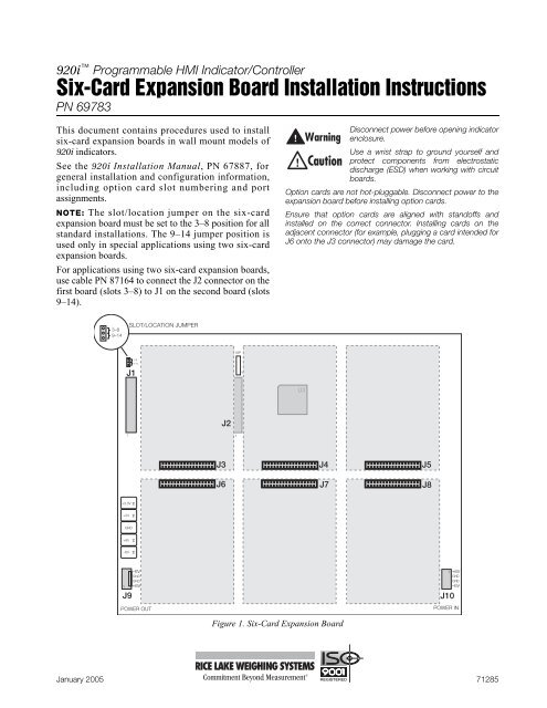
NOTE: The slot/location jumper on the six-card<br />
expansion board must be set to the 3–8 position for all<br />
standard installations. The 9–14 jumper position is<br />
used only in special applications using two six-card<br />
expansion boards.<br />
For applications using two six-card expansion boards,<br />
use cable PN 87164 to connect the J2 connector on the<br />
first board (slots 3–8) to J1 on the second board (slots<br />
9–14).<br />
Disconnect power before opening indicator<br />
enclosure.<br />
Use a wrist strap to ground yourself and<br />
protect components from electrostatic<br />
discharge (ESD) when working with circuit<br />
boards.<br />
Option cards are not hot-pluggable. Disconnect power to the<br />
expansion board before installing option cards.<br />
Ensure that option cards are aligned with standoffs and<br />
installed on the correct connector. Installing cards on the<br />
adjacent connector (for example, plugging a card intended for<br />
J6 onto the J3 connector) may damage the card.<br />
3–8<br />
9–14<br />
SLOT/LOCATION JUMPER<br />
ISP<br />
3–8<br />
J1<br />
9–14<br />
1<br />
U3<br />
J2<br />
1<br />
1<br />
J3 J4 J5<br />
J6<br />
J7<br />
J8<br />
+3.3V<br />
+5V<br />
GND<br />
+6V<br />
–6V<br />
–6V<br />
GND<br />
GND<br />
1 +6V<br />
J9<br />
POWER OUT<br />
Figure 1. <strong>Six</strong>-<strong>Card</strong> <strong>Expansion</strong> <strong>Board</strong><br />
1 +6V<br />
GND<br />
GND<br />
–6V<br />
J10<br />
POWER IN<br />
January 2005 71285
Wall Mount <strong>Installation</strong><br />
Use the following procedure to install the six-card<br />
expansion board in the wall mount enclosure. See<br />
Figure 2 below and Figure 3 on page 3 for locations of<br />
option kit components.<br />
1. Disconnect indicator from power source.<br />
2. Open enclosure.<br />
3. Clip the six cable ties that secure the cable<br />
assembly from the power supply to the CPU<br />
board. Remove power supply cable.<br />
4. Remove adhesive covering from two ribbon<br />
cable clamps and install on door and side wall<br />
of enclosure (see Figure 2 on page 2).<br />
5. Mount six-card expansion board on studs at<br />
back of enclosure. Use ten 1/4" screws (PN<br />
14839) to secure board to studs (see Figure 3<br />
on page 3 for screw locations).<br />
6. Attach ribbon cable to connector J7 on the<br />
CPU board, with the striped edge of the cable<br />
on the pin 1 side of the connector. (See<br />
Figure 3 on page 3 for connector and pin<br />
locations.)<br />
7. Slide the ribbon cable into the cable clamps<br />
and attach to connector J1 on the expansion<br />
board, with the striped edge of the cable on the<br />
pin 1 side of connector J1. Note that the ribbon<br />
cable must be folded (see Figure 2) for correct<br />
orientation at the connector.<br />
8. Attach long power cable assembly from<br />
connector J9 on the expansion board to the<br />
power input on the CPU board.<br />
9. Attach short power cable assembly from power<br />
supply to connector J10 on the expansion<br />
board.<br />
10. Set the slot/location jumper to the 3–8 position<br />
(see Figure 1 on page 1).<br />
11. Install option cards onto expansion board (see<br />
page 3). Use the supplied cable ties to secure<br />
all loose cables inside the enclosure.<br />
RIBBON CABLE<br />
CLAMPS<br />
INSTALLED<br />
OPTION CARDS<br />
ON SIX-CARD<br />
EXPANSION BOARD<br />
Figure 2. <strong>Six</strong>-<strong>Card</strong> <strong>Expansion</strong> <strong>Board</strong> Installed in Wall Mount Enclosure, Isometric View<br />
2 <strong>920i</strong> <strong>Six</strong>-<strong>Card</strong> <strong>Expansion</strong> <strong>Board</strong> <strong>Installation</strong> <strong>Instructions</strong>
SIX-CARD<br />
EXPANSION BOARD<br />
RIBBON CABLE<br />
J7<br />
PIN 1<br />
J1<br />
PIN 1<br />
1/4"<br />
SCREWS<br />
(10)<br />
J9<br />
J10<br />
POWER OUTPUT<br />
TO CPU BOARD<br />
POWER SUPPLY CABLE<br />
TO EXPANSION BOARD<br />
POWER SUPPLY<br />
CABLE TO CPU BOARD<br />
POWER SUPPLY<br />
Figure 3. <strong>Six</strong>-<strong>Card</strong> <strong>Expansion</strong> <strong>Board</strong> Installed in Wall Mount Enclosure<br />
Installing Option <strong>Card</strong>s<br />
Each option card is shipped with installation<br />
instructions specific to that card. The general procedure<br />
for all option cards is as follows:<br />
Option cards are not hot-pluggable.<br />
Disconnect power to the <strong>920i</strong> before<br />
installing option cards.<br />
Ensure that option cards are aligned with standoffs and<br />
installed on the correct connector. Installing cards on the<br />
adjacent connector (for example, plugging a card intended for<br />
J6 onto the J3 connector) may damage the card.<br />
1. Carefully align the large option card connector<br />
with connector J3–J8 on the expansion board.<br />
Press down to seat the option card in the<br />
expansion board connector.<br />
2. Use the screws provided in the option kit to<br />
secure the other end of the option card to the<br />
threaded standoffs on the expansion board.<br />
3. Make connections to the option card as<br />
required. Use cable ties to secure loose cables<br />
inside the enclosure.<br />
4. When installation is complete, secure the<br />
enclosure door and reconnect power to the<br />
indicator.<br />
The <strong>920i</strong> automatically recognizes all installed<br />
option cards when the unit is powered on. No<br />
hardware-specific configuration is required to<br />
identify the newly-installed card to the system.<br />
3


