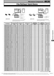
Ceramic Trimmer Capacitors - Murata
Ceramic Trimmer Capacitors - Murata
Ceramic Trimmer Capacitors - Murata

Create successful ePaper yourself
Turn your PDF publications into a flip-book with our unique Google optimized e-Paper software.
!Note • Please read rating and !CAUTION (for storage, operating, rating, soldering, mounting and handling) in this catalog to prevent smoking and/or burning, etc.<br />
• This catalog has only typical specifications. Therefore, please approve our product specifi cations or transact the approval sheet for product specifi cations before ordering.<br />
T13E.pdf<br />
Nov.22,2013<br />
c Notice (Soldering and Mounting)<br />
1. Soldering<br />
(1) Can be soldered by refl ow soldering method, fl ow<br />
soldering method, and soldering iron.<br />
(2) Soldering conditions<br />
Refer to the temperature profi le.<br />
If the soldering conditions are not suitable, e.g.,<br />
excessive time and/or excessive temperature, the<br />
trimmer capacitor may deviate from the specifi ed<br />
characteristics.<br />
(3) The amount of solder is critical.<br />
(4) The thickness of solder paste should be printed<br />
from 150 micro m to 200 micro m and the dimension<br />
of land pattern should be <strong>Murata</strong>'s standard land<br />
pattern used at refl ow soldering. Insuffi cient<br />
amounts of solder can lead to insuffi cient<br />
soldering strength on PCB. Excessive amounts of<br />
solder may cause bridging between the terminals<br />
or contact failure due to fl ux wicking up.<br />
(5) When using soldering iron, the string solder<br />
shall be applied to the lower part of the<br />
terminal only. Do not apply fl ux except to the<br />
terminals. Excessive amounts of solder and/or<br />
applying solder to the upper part of the<br />
terminal may cause fi xed rotor or contact failure<br />
due to fl ux invasion into the movable part and/or<br />
the contact point. The soldering iron should not<br />
come in contact with the plastic case of the<br />
trimmer capacitor. If such contact does occur,<br />
the trimmer capacitor may be damaged.<br />
(6) Our recommended chlorine content of solder is<br />
as follows.<br />
(a) Solder paste: 0.2wt% max.<br />
(b) String solder: 0.5wt% max.<br />
(7) Do not use water-soluble fl ux (for water<br />
cleaning). To prevent the deterioration of<br />
trimmer capacitor characteristics, apply fl ux<br />
only to terminals.<br />
2. Mounting<br />
(1) Do not apply excessive force (preferably 5.0N<br />
[Ref: 500gf] max.), when the trimmer capacitor<br />
is mounted on the PCB.<br />
(2) Do not warp and/or bend PCB to protect trimmer<br />
capacitor from breakage.<br />
(3) When bending the terminals, do not apply<br />
excessive force to the body of the product to<br />
protect the terminal fi xing part from damage.<br />
(4) Use a pick-up nozzle of a suitable dimension.<br />
> Without cover fi lm type<br />
- External dimensions of 4.5x4.0mm and<br />
2.5mm bore diameter.<br />
> With cover fi lm type<br />
- 4.0mm external diameter and 2.0mm bore<br />
diameter.<br />
3. Cleaning [with cover fi lm type]<br />
Isopropyl alcohol and ethyl alcohol are available<br />
material for cleaning. If you use any other type of<br />
solvent, please evaluate performance in your<br />
application. Moreover, please confi rm that no<br />
damage has occurred to the trimmer capacitor<br />
after cleaning in your conditions.<br />
4. Other<br />
Note the polarity of the trimmer capacitor to<br />
minimize infl uence by stray capacitance.<br />
(Refer to the dimensions concerning the polarity.)<br />
c Notice (Handling)<br />
1. Use suitable screwdrivers that fi t comfortably in<br />
driver slot.<br />
(1) Recommended screwdriver for manual adjustment<br />
MURATA: KMDR010<br />
(2) Recommended screwdriver bit for automatic<br />
adjustment<br />
MURATA: KMBT010<br />
2. When adjusting with a screwdriver, do not apply<br />
excessive force (preferably 1.0 N [Ref: 100gf] max.)<br />
to minimize capacitance drift. Excessive force applied<br />
to the screwdriver slot may cause deformation of the<br />
products.<br />
3. Do not apply adhesive, lock paints, or any other<br />
substances to the trimmer capacitor to secure the<br />
rotor position. They may cause corrosion or<br />
electrical contact problems.<br />
4. Do not break the cover fi lm before the completion<br />
of PCB mounting, soldering, and cleaning.<br />
5. Do not clean the trimmer capacitor after the cover<br />
fi lm has been broken.<br />
6. To break the cover fi lm, fi rst turn the screwdriver<br />
more than 360°, and set the capacitance value.<br />
(Inserting the screwdriver only will not break the<br />
cover fi lm.)<br />
7<br />
c Notice (Other)<br />
Before using trimmer capacitors, please test after<br />
assembly in your particular mass production system.<br />
31