


You also want an ePaper? Increase the reach of your titles
YUMPU automatically turns print PDFs into web optimized ePapers that Google loves.
GlassWare Audio Design<br />
Power Transformer(s)<br />
The <strong>12B4</strong> <strong>CCDA</strong> PCB requires a power transformer(s) to energize its two power<br />
supplies. The heater power supply power transformer must offer at least 1.8 times<br />
more current than the heaters will draw. For example, four <strong>12B4</strong>s will draw 1.2A<br />
@12.6v, so the heater power transformer must be able to sustain an AC 2.16A current<br />
draw (2.5A is good choice). In addition, with sine waves, the AC voltage equals the<br />
peak voltage divided by the square root of 2, i.e. 1.414. Thus, a 10Vac sine wave peaks<br />
at 14.14V; a 6.3Vac, 8.9V. In other words, a sine wave that peaks at 14.14V will<br />
produce the same amount of heat in a resistance as a 10Vdc voltage source would<br />
produce in the same resistance; thus, we label the 14.14Vpk sine wave as being 10Vac.<br />
Thus, in order to get the 16Vdc raw DC voltage that a 12.6V heater voltage regulator<br />
requires an input voltage equal to remainder of 16V minus the rectifier loss (about<br />
2V) divided by 1.414, which is roughly 12.6Vac.<br />
The high voltage power transformer must also follow the same rules. Thus, to achieve<br />
300V of raw DC voltage, the transformer primary must deliver (300V + 2V) / 1.414,<br />
or about 214Vac. And if 50mA is required, the power transformer must be rated for<br />
50mA x 1.8 (in a full-wave bridge rectifier circuit), or 90mA. Thus, such a transformer<br />
VA rating would be rated about 20VA, as 0.9 x 214 = 19.71.<br />
I out<br />
=<br />
V dc<br />
=<br />
I ac<br />
/ 1.8<br />
(V ac<br />
x 1.4) - 2V diode<br />
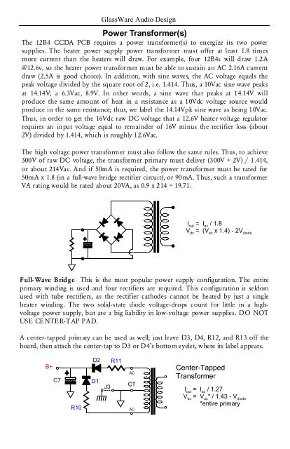
Full- Wave Bridge This is the most popular power supply configuration. The entire<br />
primary winding is used and four rectifiers are required. This configuration is seldom<br />
used with tube rectifiers, as the rectifier cathodes cannot be heated by just a single<br />
heater winding. The two solid-state diode voltage-drops count for little in a highvoltage<br />
power supply, but are a big liability in low-voltage power supplies. DO NOT<br />
USE CE NTER-T AP PAD.<br />
A center-tapped primary can be used as well; just leave D3, D4, R12, and R13 off the<br />
board, then attach the center-tap to D3 or D4’s bottom eyelet, where its label appears.<br />
B+<br />
C7<br />
R10<br />
D2<br />
R11<br />
D1<br />
J3<br />
AC<br />
Transformer<br />
Center-Tapped<br />
CT<br />
AC<br />
I out<br />
=<br />
V dc<br />
=<br />
I ac<br />
/ 1.27<br />
V ac<br />
* / 1.43 - V diode<br />
*entire primary


