


You also want an ePaper? Increase the reach of your titles
YUMPU automatically turns print PDFs into web optimized ePapers that Google loves.
GlassWare Audio Design<br />
Unlike the Aikido circuit, which delivers a perfect platform for tube rolling, as vastly<br />
different tubes can be swapped in and out of the board (6AQ8 or 6H30) without<br />
having to change the resistor values, the <strong>12B4</strong> <strong>CCDA</strong> requires more care in selecting<br />
resistor values. The problem is the daunting array of different possible B+ voltages<br />
and idle currents. For example, a <strong>12B4</strong> <strong>CCDA</strong> might run a B+ voltage of only 100Vdc<br />
or as much as 300Vdc. Moreover, the plate resistor cannot be the little 1/2W devices<br />
that the Aikido freely uses, but big 2W (or 3W) power resistors, which are hard to<br />
find and expensive. The solution the problem of too many resistor combinations is to<br />
let the idle current move, but lock the plate and cathode resistor values. A triode with<br />
a cathode and plate resistors acts like a resistor, not a perfect resistor, but a fairly<br />
good one.<br />
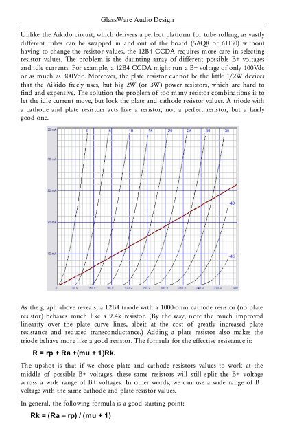
As the graph above reveals, a <strong>12B4</strong> triode with a 1000-ohm cathode resistor (no plate<br />
resistor) behaves much like a 9.4k resistor. (By the way, note the much improved<br />
linearity over the plate curve lines, albeit at the cost of greatly increased plate<br />
resistance and reduced transconductance.) Adding a plate resistor also makes the<br />
triode behave more like a good resistor. The formula for the effective resistance is:<br />
R = rp + Ra +(mu + 1)Rk.<br />
The upshot is that if we chose plate and cathode resistors values to work at the<br />
middle of possible B+ voltages, these same resistors will still split the B+ voltage<br />
across a wide range of B+ voltages. In other words, we can use a wide range of B+<br />
voltage with the same cathode and plate resistor values.<br />
In general, the following formula is a good starting point:<br />
Rk = (Ra – rp) / (mu + 1)


