


You also want an ePaper? Increase the reach of your titles
YUMPU automatically turns print PDFs into web optimized ePapers that Google loves.
GlassWare Audio Design<br />
Introduction to the <strong>CCDA</strong> Circuit<br />
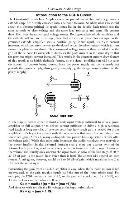
The Constant-Current-Draw Amplifier is a compound circuit that holds a groundedcathode<br />
amplifier directly cascaded into a cathode follower. So what; what’s so special<br />
about this obvious pairing Its special status lies in the details. Each triode sees the<br />
same cathode to plate voltage and the same load resistance and same idle current<br />
draw. Each sees the same signal voltage swings. Both grounded-cathode amplifier and<br />
the cathode follower are in voltage phase, but not current phase. For example, as the<br />
grounded-cathode amplifier sees a positive going input signal, its plate current<br />
increases, which increases the voltage developed across the plate resistor, which in turn<br />
swings the plate voltage down. This downward voltage swing is then cascaded into the<br />
grid of the cathode follower, which decreases the plate current to the same degree that<br />
the previous stage's current increased. This results in the constant current draw feature<br />
of this topology (a highly desirable feature, as the signal amplification will not alter<br />
the amount of current being sourced from the power supply and consequently not<br />
perturb the power supply, thus greatly simplifying the design consideration of the<br />
power supply).<br />
R load<br />
B+<br />
B+<br />
2<br />
in<br />
1µF<br />
out<br />
1M<br />
Rk<br />
R load<br />
1M<br />
<strong>CCDA</strong> Topology<br />
A line stage is needed either to boast a weak signal voltage sufficient to drive a power<br />
amplifier to full output, or to deliver current sufficient to drive a high capacitance<br />
load (such as long stretches of interconnect). Just how much gain is needed for a line<br />
amplifier Let's begin the answer with the observation that most line amplifiers have<br />
too much gain. (After all, many audiophile run passive line-stage setups, which offer<br />
no voltage gain.) While this extra gain impresses the audio neophyte who marvels at<br />
the power implicit in the distorted thunder that a mere one quarter twist of the<br />
volume knob provokes, it ultimately only subtracts from the useful range of turn on<br />
the volume and usually only worsens the signal-to-noise ratio of the line stage. If 20 to<br />
30 dB of gain is too much, how much then is best The answer will depend on each<br />
system. A safe guess, however, would be 6 to 20 dB of gain, which translates into 2 to<br />
10 times the input signal.<br />
Calculating the gain from a <strong>CCDA</strong> amplifier is easy, when the cathode resistor is left<br />
un-bypassed, as the gain roughly equals half the mu of the input triode used. For<br />
example, the <strong>12B4</strong> presents a mu of 6.5, so the gain will equal about 3 (+9.5dB), not<br />
3.5 due to losses in the cathode follower.<br />
Gain = muRa / (rp + Ra + [mu +1]Rk)<br />
And since we wish to split the B+ voltage at the input tube's plate,<br />
Ra = rp + (mu + 1)Rk


