


You also want an ePaper? Increase the reach of your titles
YUMPU automatically turns print PDFs into web optimized ePapers that Google loves.
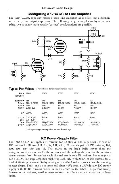
GlassWare Audio Design<br />
Configuring a <strong>12B4</strong> <strong>CCDA</strong> Line Amplifier<br />
The <strong>12B4</strong> <strong>CCDA</strong> topology makes a good line amplifier, as it offers low distortion<br />
and a fairly low output impedance. The following design examples are by no means<br />
exhaustive, as many more equally “correct” configurations are possible.<br />
R8b<br />
R6a<br />
R6b<br />
V2<br />
C4<br />
R8a<br />
C3<br />
B+<br />
R4<br />
C1<br />
Output<br />
Input<br />
R2<br />
V1<br />
D11<br />
R5<br />
C2<br />
R10<br />
C1<br />
G<br />
C2<br />
+<br />
G<br />
R1<br />
R3<br />
R7a R7b R9<br />
Typical Part Values<br />
B+ =<br />
(at tubes)<br />
R1,9,10 =<br />
R2,4 =<br />
R3,5 =<br />
R6,7 =<br />
() Parentheses denote recommended values<br />
100V 150V 200V 250V 300V<br />
1M 1M 1M 1M 1M<br />
100-1k (300) 100-1k (300) 100-1k (300) 100-1k (300) 100-1k (300)<br />
100 270 470 820 1150<br />
2.15k 2W 3.4k 2W 5k 3W 7.5k 3W 10k 3W<br />
Iq =<br />
23mA 22mA 20mA 17mA 15mA<br />
C1,2 =<br />
C3 =<br />
C4 =<br />
C7,8 =<br />
0.1 - 10µF* Same Same Same Same<br />
0.1 - 1µF* " " " "<br />
270µF/200V 270µF/200V 150µF/400V 150µF/400V 150µF/400V<br />
220µF/200V 220µF/200V 47µF/450V 47µF/450V 47µF/450V<br />
*Voltage rating must equal or exceed B+ voltage<br />
RC Power-Supply Filter<br />
The <strong>12B4</strong> <strong>CCDA</strong> kit supplies 24 resistors for R8 (R8a & R8b in parallel): six pairs of<br />
3W resistors for R8 use: 1.6k, 2k, 3k, 3.9k, 6.8k, 10k, and six pairs of 1W resistors, 100,<br />
200, 300, 470, 680, and 1k. The charts on the back inside cover show the<br />
voltage/current maximums for the resistors and the voltage drop across the resistors<br />
versus current flow. Remember each channel gets it own R8 resistor. For example, a<br />
<strong>12B4</strong> <strong>CCDA</strong> line- stage amplifier might run each tube with 20mA of idle current, for a<br />
total of 40mA per channel. So by looking up the 40mA column, we can see the resulting<br />
voltage drops. Thus, one 1k resistor will drop 40V; thus, a 290Vdc raw DC power<br />
supply with 1k R8 resistors would deliver 250Vdc to the tubes. To prevent risking<br />
damage to the resistors, avoid running resistors near the excessive current and voltage<br />
limits.


