


Create successful ePaper yourself
Turn your PDF publications into a flip-book with our unique Google optimized e-Paper software.
GlassWare Audio Design<br />
Grounding<br />
The <strong>12B4</strong> <strong>CCDA</strong> PCB holds a star ground at its center. Ideally, this will be the only<br />
central ground in the line-stage amplifier. Ground loops, however, are extremely easy<br />
to introduce. For example, if the RCA jacks are not isolated from the chassis, then the<br />
twisted pair of wires that connect the PCB to the jacks will each define a ground loop<br />
(as will jumper J3, which bridges the PCB’s ground to the chassis). The solution is<br />
either to isolate the jacks or use only a single hot wire from jack to PCB (the wire can<br />
be shielded, as long as the shield only attaches at one end). Thus, the best plan is to<br />
plan. Before assembling the line-stage amplifier, stop and decide how the grounding is<br />
going to be laid out, then solder.<br />
Three different schools of thought hold for grounding a piece of audio gear. The Old-<br />
School approach is to treat the chassis as the ground; period. E very ground connection<br />
is made at the closest screw and nut. This method is the easiest to follow and it<br />
produces the worst sonic results. Steel and aluminum are poor conductors.<br />
The Semi-Star ground method uses several ground “stars” that are often called spurs,<br />
which then terminate in a single star ground point, often a screw on the chassis. This<br />
system can work beautifully, if carefully executed. Unfortunately, often too much is<br />
included in each spur connection. For example, all the input and output RCA jacks<br />
share ground connection to a long run of bare wire, which more closely resembles a<br />
snake than a spur ground. In other words, the spurs should not be defined just physical<br />
proximity, but signal transference. Great care must be exercised not to double ground<br />
any spur point. For example, the volume control potentiometer can create a ground<br />
loop problem, if both of its ground tabs are soldered together at the potentiometer and<br />
twisted pairs, of hot and cold wires, arrive at and leave the potentiometer, as the two<br />
cold wires attaching to the PCB will define a ground loop.<br />
The Absolute-Star grounding scheme uses a lot of wire and is the most time consuming<br />
to execute, but it does yield the best sonic rewards. Here each input signal source and<br />
each output lead gets its own ground wire that attaches, ultimately, at one star ground<br />
point; each RCA jack is isolated from the chassis. The <strong>12B4</strong> <strong>CCDA</strong> PCB was designed<br />
to work with this approach, although it can be used with any approach.<br />
House Ground T he third prong on the wall outlet attaches to the house’s ground,<br />
usually the cold water pipe. T he line-stage amplifier can also attach to this ground<br />
connection, which is certainly the safest approach, as it provides a discharge path<br />
should the B+ short to the chassis. Unfortunately, this setup often produces a hum<br />
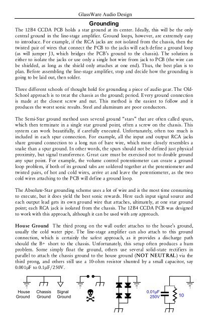
problem. Some simply float the ground, others use several solid-state rectifiers in<br />
parallel to attach the chassis ground to the house ground (NOT NEUT RAL) via the<br />
third prong, and others still use a 10-ohm resistor shunted by a small capacitor, say<br />
0.001µF to 0.1µF/250V.<br />
House<br />
Ground<br />
<br />
Chassis Signal<br />
0.01µF<br />
Ground Ground<br />
250V 10


