Lab 5: Ohm's Law
Lab 5: Ohm's Law
Lab 5: Ohm's Law

Create successful ePaper yourself
Turn your PDF publications into a flip-book with our unique Google optimized e-Paper software.
5 Ohm’s <strong>Law</strong><br />
In addition to reading this assignment, you may need to refer to Appendix A on<br />
uncertainties and Appendix B on linear regressions.<br />
Introduction<br />
Ohm’s <strong>Law</strong><br />
The current flowing through an Ohmic device is directly proportional to the potential<br />
difference ∆V between its terminals,<br />
∆V = iR (1)<br />
The constant of proportionality R is called the resistance of the device. This relationship is<br />
knownasOhm’s <strong>Law</strong>. Youwillinvestigatethedependence ofcurrent onpotentialdifference<br />
in resistors and light bulbs. Your job will be to determine whether or not these devices are<br />
Ohmic and if so to determine their resistances.<br />
R<br />
1<br />
R<br />
2<br />
R eq<br />
R 1 R 2<br />
R eq<br />
Series<br />
Parallel<br />
(a)<br />
(b)<br />
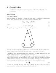
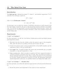
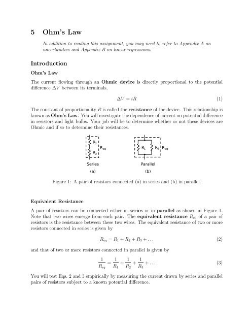
Figure 1: A pair of resistors connected (a) in series and (b) in parallel.<br />
Equivalent Resistance<br />
A pair of resistors can be connected either in series or in parallel as shown in Figure 1.<br />
Note that two wires emerge from each pair. The equivalent resistance R eq of a pair of<br />
resistors is the resistance between these two wires. The equivalent resistance of two or more<br />
resistors connected in series is given by<br />
R eq = R 1 +R 2 +R 3 +... (2)<br />
and that of two or more resistors connected in parallel is given by<br />
1<br />
R eq<br />
= 1 R 1<br />
+ 1 R 2<br />
+ 1 R 3<br />
+... (3)<br />
You will test Eqs. 2 and 3 empirically by measuring the current drawn by series and parallel<br />
pairs of resistors subject to a known potential difference.
Resistor Color Codes<br />
Most resistors you will encounter are marked with a set of bands, according to a standard<br />
color code, which you can use to determine their resistances. There are ten colors corresponding<br />
to numerical digits 0-9 (See the table below.), and gold and silver bands indicating<br />
5% and 10% accuracy in the coded resistance, respectively. Starting at the far end of the resistor<br />
from the gold/silver band, the first two bands are the first two digits in the resistance.<br />
The third band gives the power of ten by which you multiply the first two digits to obtain<br />
the resistance.<br />
color black brown red orange yellow green blue violet gray white<br />
digit 0 1 2 3 4 5 6 7 8 9<br />
multiplier 1 10 100 1k 10k 100k 1M 10M 100M 1000M<br />
R = [band1][band2]×10 [band3] ± 5%(gold) (4)<br />
± 10%(silver)<br />
For example, Blue Yellow Red Gold gives R = 64 ×10 2 Ω = 64×100 Ω = 6400 Ω with a<br />
tolerance of 5%, or ±320 Ω.<br />
Experiment<br />
You have been supplied with three resistors, a light bulb, a power supply, several wires<br />
for connecting them, and a digital multimeter (DMM) for measuring potential differences<br />
(voltages), currents, and resistances.<br />
Warnings<br />
1. Before turning on the power supply or connecting it to a circuit, make sure that the<br />
switch for the voltage range is in the 0-8 V position, and that the Voltage Increase dial<br />
is turned all the way down (the counter-clockwise direction). Then slowly increase the<br />
voltage as needed. Do not put more than 3 V across a light bulb!<br />
2. When using the DMM as an ammeter (i.e. to measure current) ...<br />
(a) make sure the red lead is plugged into the port on the DMM labeled for measuring<br />
current. Start with the one for large currents (10 A or 20 A), and move to the<br />
more sensitive port(s) if you find that you need better precision.<br />
(b) always be certain to connect it in series with the device through which you are trying<br />
to measure the current. Never connect an ammeter in parallel with anything,<br />
or you will blow its fuse!<br />
3. When using the DMM as a voltmeter or ohmmeter, make sure the red lead is plugged<br />
into the voltage port, and make sure to connect it in parallel with the device(s) of<br />
interest. (Connecting a voltmeter or Ohmmeter in series with something doesn’t make<br />
any sense, but it also doesn’t blow any fuses.)
A<br />
E R V<br />
E<br />
R<br />
(b)<br />
(c)<br />
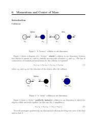
Figure 2: (a) A simple circuit consisting of a voltage source connected in series with a<br />
resistor. (b) The same circuit with a voltmeter to measure the potential difference between<br />
its terminals. (c) The same circuit with an ammeter to measure the current.<br />
Resistance<br />
1. Set up the circuit shown in Figure 2a with one of your resistors.<br />
2. Record the resistance and uncertainty indicated by the color code on the resistor.<br />
3. Set the emf of the power supply to a value in the range 0 < E < 3 V.<br />
4. Plug the red lead of the DMM into the voltage port, and connect the DMM in parallel<br />
with the resistor as shown in Figure 2b. Turn the knob on the DMM to a suitable<br />
voltage scale, and record the voltage across the resistor.<br />
5. Plug the red lead of the DMM into the current port, and connect the DMM in series<br />
with the resistor as shown in Figure 2c. Remember never to connect an ammeter in<br />
parallel with anything! Turn the knob on the DMM to a suitable current scale, and<br />
record the current through the resistor.<br />
6. Repeat steps 3-5 for four other source emfs in the range 0 < E < 3 V.<br />
7. Repeat the whole process (steps 3-6) with the light bulb instead of a resistor. In<br />
choosing your source emfs be sure that all of your source emfs are below 3 V and<br />
that you cover, with at least three measurements, the low-voltage range in which the<br />
filament does not glow.<br />
8. Use the DMM to measure the resistances of the resistor and light bulb you used. Ask<br />
for help if you need it.<br />
Equivalent Resistance<br />
1. Set up the circuit shown in Figure 3a.<br />
2. Set the source emf to about 1 V.<br />
3. Use the DMM to measure the voltages V 1 and V 2 across each of the resistors and the<br />
voltage V across the pair.<br />
4. UsetheDMMtomeasurethecurrentthroughtheresistors. Remember never to connect<br />
an ammeter in parallel with anything!
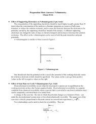
Figure 3: A voltage source connected in series with (a) two resistors connected in series and<br />
(b) two resistors connected in parallel.<br />
5. Set up the circuit shown in Figure 3b.<br />
6. Keep the source emf at about 1 V.<br />
7. Use the DMM to measure the voltage across the resistors.<br />
8. Use the DMM to measure the currents i 1 and i 2 flowing through each of the resistors<br />
and the current i flowing into the pair. Remember never to connect an ammeter in<br />
parallel with anything!<br />
9. Use the DMM to measure the resistances of the resistors.<br />
Analysis<br />
Resistance<br />
1. Put your voltage and current data into a spreadsheet, and plot V vs i for the resistor<br />
and the light bulb.<br />
2. Are your data compatible with a linear model If so, use the LINEST function to find<br />
the slope of a linear fit to the data and its uncertainty (see Appendix A).<br />
Equivalent Resistance<br />
1. Use your voltage and current measurements (i and V) and Ohm’s law (Eq. 1) to<br />
determine the equivalent resistances of the series and parallel pairs of resistors.<br />
2. Use the resistances you measured with the DMM and Eqs. 2 and 3 to calculate the<br />
predicted equivalent resistances of your series and parallel pairs of resistors.<br />
3. Is there an obvious relationship between your measured V 1 , V 2 , and V in the series<br />
circuit How about between i 1 , i 2 , and i in the parallel circuit<br />
Questions<br />
1. For the resistor you studied in detail, give the resistance indicated by the color codes,<br />
the resistance you measured with the DMM, and the resistance you extracted from
your V vs. i graph with uncertainties. Are they consistent with each other within<br />
uncertainty<br />
2. Is the light bulb you studied an Ohmic device Give reasoning based on your data.<br />
3. Compare your measurement of the resistance of the light bulb with your graph of V<br />
vs. i. What might be going on here<br />
4. What relationships, if any, did you find between V 1 , V 2 , and V in the series circuit and<br />
between i 1 , i 2 , and i in the parallel circuit<br />
5. Do the equivalent resistances you determined from your voltage and current measurements<br />
agree with the predictions of Eqs. 2 and 3 within uncertainty Include your<br />
results in your response.