Reznor
Reznor
Reznor

Create successful ePaper yourself
Turn your PDF publications into a flip-book with our unique Google optimized e-Paper software.
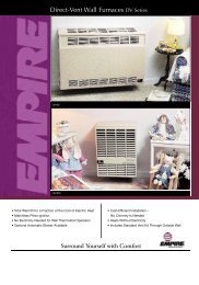
®<br />
UNIT HEATER<br />
CATALOG<br />
COMMERCIAL/INDUSTRIAL HEATERS<br />
RESIDENTIAL GARAGE HEATERS<br />
FUEL<br />
Natural Gas<br />
Propane<br />
Fuel Oil<br />
CAPACITIES<br />
25 - 1,200 MBH<br />
80% - 93% Thermal Efficiency<br />
380 - 16,750 CFM<br />
AIR DELIVERY<br />
Propeller Fan<br />
Centrifugal Blower (Ductable)<br />
Visit www.RezSpec.com for more<br />
information.<br />
Form C-UH (Version H)
BACKGROUND<br />
<strong>Reznor</strong> was founded in 1888 to manufacture the “<strong>Reznor</strong>” reflector<br />
heater, which used a luminous flame gas burner developed by George<br />
<strong>Reznor</strong>. This technological breakthrough was an immediate success<br />
and hastened the expansion of gas heating in residential and commercial<br />
applications. Technological development and innovation have<br />
been the hallmark of <strong>Reznor</strong> products through the years. The development<br />
of the forced air gas unit heater, the modular Thermocore ® heat<br />
exchanger, and the high-efficiency, V3 ® Series unit heaters have kept<br />
<strong>Reznor</strong> products at the forefront of technological advances in commercial<br />
and industrial gas heating. As a result of this pioneering role in<br />
the heating, makeup air, and ventilating equipment field, the products<br />
offered today are the most advanced in engineering design to satisfy a<br />
wide variety of applications.<br />
FACILITIES<br />
<strong>Reznor</strong> heaters were first manufactured and sold in Mercer, Pennsylvania<br />
(70 miles north of Pittsburgh) in 1888. Over the years, the company<br />
has grown and expanded. Today, with sales worldwide, <strong>Reznor</strong><br />
products are being manufactured at facilities throughout North America<br />
and Europe.<br />
PRODUCT SCOPE<br />
Well-equipped engineering laboratories for both product development<br />
and testing can be found at many of the manufacturing sites. All domestic<br />
lab sites are agency approved.<br />
<strong>Reznor</strong> Products include a complete line of heating, makeup air and<br />
ventilating systems, using gas, oil, hot water/steam, or electric heat<br />
sources. <strong>Reznor</strong> heater catalogs are designed to aid the engineer, architect<br />
or contractor in specifying the correct equipment for all standard<br />
and special applications. Complete data is presented on unit heaters,<br />
duct furnaces, infrared heaters, makeup air systems, pre-engineered<br />
custom-designed systems, and evaporative cooling modules. Consult<br />
your local <strong>Reznor</strong> Sales Representative for further assistance in specifying<br />
<strong>Reznor</strong> Equipment for your specific application.<br />
SERVICES<br />
Product service requirements are handled through contractors and/or<br />
distributors, with backup from local representatives and factory-based<br />
service team. Replacement parts inventories for both warranty and<br />
non-warranty requirements are maintained at service centers throughout<br />
the country and at the manufacturing facilities.<br />
For the <strong>Reznor</strong> Representative in your area call 800-695-1901.
Unit Heater Catalog<br />
Page Number _______ of ______<br />
Model UEAS<br />
Model UDAP<br />
Model F<br />
Contents<br />
Model UEAS....................................................................................................... 2<br />
DESCRIPTION........................................................................................ 2<br />
TECHNICAL DATA.................................................................................. 3<br />
DIMENSIONS......................................................................................... 4<br />
Model UDAS....................................................................................................... 5<br />
DESCRIPTION........................................................................................ 5<br />
TECHNICAL DATA.................................................................................. 6<br />
DIMENSIONS......................................................................................... 7<br />
Model UDAP....................................................................................................... 8<br />
DESCRIPTION........................................................................................ 8<br />
TECHNICAL DATA.................................................................................. 9<br />
DIMENSIONS....................................................................................... 10<br />
Model UDBS..................................................................................................... 11<br />
DESCRIPTION...................................................................................... 11<br />
TECHNICAL DATA................................................................................ 12<br />
DIMENSIONS....................................................................................... 13<br />
Model UDBP..................................................................................................... 14<br />
DESCRIPTION...................................................................................... 14<br />
TECHNICAL DATA................................................................................ 15<br />
DIMENSIONS....................................................................................... 16<br />
MODEL F............................................................................................................. 17<br />
DESCRIPTION...................................................................................... 17<br />
TECHNICAL DATA................................................................................ 18<br />
DIMENSIONS....................................................................................... 19<br />
MODEL B............................................................................................................. 20<br />
DESCRIPTION...................................................................................... 20<br />
TECHNICAL DATA................................................................................ 21<br />
DIMENSIONS....................................................................................... 22<br />
MODEL OH.......................................................................................................... 23<br />
DESCRIPTION...................................................................................... 23<br />
TECHNICAL DATA................................................................................ 24<br />
DIMENSIONS....................................................................................... 24<br />
Model LDAP...................................................................................................... 25<br />
DESCRIPTION...................................................................................... 25<br />
TECHNICAL DATA................................................................................ 26<br />
DIMENSIONS....................................................................................... 26<br />
Throw/Floor Coverage............................................................................. 28<br />
Sound Data...................................................................................................... 33<br />
BLOWER CHARTS............................................................................................. 34<br />
MOTOR FULL LOAD AMP TABLE..................................................................... 36<br />
Installation Procedures......................................................................... 37<br />
Options and Accessories......................................................................... 39<br />
<strong>Reznor</strong> Separated Combustion Systems............................................ 43<br />
<strong>Reznor</strong> RezPro ® Toolbox Software.................................................... 44<br />
Sample Specifications............................................................................... 46<br />
Model UEAS.............................................................................................. 46<br />
Model UDAS.............................................................................................. 47<br />
Model UDBS.............................................................................................. 48<br />
Model UDAP.............................................................................................. 49<br />
Model UDBP.............................................................................................. 50<br />
Model F...................................................................................................... 51<br />
Model B...................................................................................................... 52<br />
Model OH................................................................................................... 52<br />
Model LDAP............................................................................................... 52<br />
REZNOR ® PRODUCT LIMITED WARRANTY..................................................... 53<br />
Model LDAP<br />
For installations where dirt, dust, and other air borne contamination is present in the indoor<br />
environment, it is recommended to use separated combustion units (UDAS, UDBS).<br />
These models use air from outside the space for combustion. This will help reduce the<br />
build up of contaminates on the burner which would affect the combustion process. Refer<br />
to the installation manuals for recommended frequency of maintenance and cleaning.<br />
IMPORTANT: Specifications are subject to change without notice. This guide is intended to provide specifications and technical information only.<br />
This guide is not intended to be an instruction manual. When installing heating and ventilating equipment, you must check and conform to all local and national building codes.<br />
Improper installation of heating and ventilating equipment could be dangerous. Consult manufacturer's installation manual for instructions and important warnings.<br />
Form RZ-C-UH (Version H) Page 1
Model UEAS<br />
Page Number _______ of ______<br />
Super High Efficiency<br />
Separated Combustion, Low Static Unit Heaters for Commercial/<br />
Industrial Use<br />
L<br />
I S T E D<br />
®<br />
CUSTOMER<br />
CQS<br />
AGENCY<br />
CONVERGENT<br />
QUALITY SYSTEM<br />
PRODUCT<br />
PROCESS<br />
START-UP<br />
WARRANTY<br />
DESCRIPTION<br />
STANDARD FEATURES<br />
OPTIONAL FEATURES -<br />
FACTORY INSTALLED<br />
<strong>Reznor</strong> ® V3 Series Model UEAS gas-fired, high efficiency, separated combustion unit heaters are available in 4<br />
sizes ranging from 131,000 to 305,000 BTUH gas input. Heaters are designed for up to 93% thermal efficiency<br />
and are approved for installation in the United States and Canada by ETL.<br />
<strong>Reznor</strong>® V3 Series unit heaters have a refreshing appearance with a glossy white cabinet finish and less visible<br />
hardware. Each size cabinet is easily suspended from 4 suspension points. The low voltage terminal strip<br />
on the outside of the cabinet makes connecting control wiring easy with no panels to remove. The addition of a<br />
“G” terminal to the low voltage strip, along with the new design of the circuit board, allows for fan only operation<br />
(without adding relays). All units have a factory installed gas line nipple to the exterior of the cabinet for easy<br />
gas service connection. The MacroChannel SM secondary heat exchanger has a 1/2” PVC pipe for attaching a<br />
coupling for ease of installation and cleaning of the required condensate drain. A 4” PVC cleanout cap that is<br />
drilled and tapped for a 1/2” NPT fitting is furnished with the heater for attaching the vent condensate drain.<br />
The preeminent new internal feature is the Tcore 3 high efficiency heat exchanger and single burner combustion<br />
system. Other standard features include a single-stage gas valve, multi-try direct spark ignition with<br />
100% lockout, pressure switch to verify vent flow, venter motor, aluminum venter wheel with housing, resiliently<br />
isolated axial fan and motor assembly, a high temperature limit control, interlock door switch, and a built-in<br />
disconnect switch. Operation is controlled through an integrated circuit board. The circuit board monitors heater<br />
operation and has LED diagnostic indicator lights to identify abnormalities in control functions.<br />
The 1 ST ever separated combustion system in the commercial/industrial heating industry was introduced<br />
on a <strong>Reznor</strong> heater in the 1960s, and that proven technology is continued in this new separated combustion<br />
product. Model UEAS separated combustion units require installation of a specially designed combustion air/<br />
vent system including the unique concentric adapter box that allows for only one building penetration for both<br />
the vent and combustion air.<br />
The V3 Series unit heaters are designed to provide all the features you expect in a <strong>Reznor</strong> heater plus improved<br />
efficiency, easier installation, and a new look ~ both inside and out. Look for the unique white unit with<br />
no visible front and bottom hardware, deep red louvers, black side handle, and angled corner to know you have<br />
a genuine <strong>Reznor</strong> unit by Thomas & Betts.<br />
●●<br />
Up to 93% Thermal efficient ~ Most efficient unit heater in the world!<br />
●●<br />
50-60°F temperature rise range<br />
●●<br />
Arranged for use with natural gas (propane conversion kit included with unit)<br />
●●<br />
NEW Tcore 3 titanium stabilized aluminized steel primary heat exchanger with extruded aluminum Macro-<br />
Channel SM secondary heat exchanger (patent pending)<br />
●●<br />
NEW patented A Tcore 3 single burner combustion system including a one-piece burner assembly<br />
●●<br />
115/1/60 Supply voltage<br />
●●<br />
115 Volt open fan motor with internal overload protection<br />
●●<br />
Transformer for 24-volt controls<br />
●●<br />
Integrated circuit board with diagnostic indicator lights<br />
●●<br />
Multi-try direct ignition with 100% lockout<br />
●●<br />
Fan relay (included on the circuit board)<br />
●●<br />
Single-stage natural gas valve (field adjustable for operation to 10,000 ft. [3,000 meters] elevation)<br />
●●<br />
Vibration/noise isolated fan motor<br />
●●<br />
Sealed control compartment houses all electrical components<br />
●●<br />
48 frame, ball bearing, PSC venter motor<br />
●●<br />
4-point Suspension<br />
●●<br />
Built-in disconnect switch (20A @ 115V Rating)<br />
●●<br />
External terminal strip for 24-volt wiring<br />
●●<br />
Sealed junction box for supply wiring<br />
●●<br />
External gas connection<br />
●●<br />
Fully gasketed door panel with safety door switch<br />
●●<br />
Full fan guard ~ engineered for safety<br />
●●<br />
Improved cabinet design with less visible hardware and a NEW <strong>Reznor</strong> appearance<br />
●●<br />
409 stainless steel primary heat exchanger<br />
●●<br />
Totally enclosed fan motor (115 V only)<br />
NOTE: Model UEAS should not be<br />
used in applications where space<br />
temperature is set below 45°F.<br />
Form RZ-C-UH (Version H) Page 2
ACCESSORIES - FIELD<br />
INSTALLED<br />
Page Number _______ of ______<br />
● ● *Horizontal or vertical combustion air/vent kit including concentric adapter<br />
●●<br />
Thermostat<br />
●●<br />
Thermostat guard with locking cover<br />
●●<br />
Vertical louvers<br />
●●<br />
Downturn nozzle kits<br />
●●<br />
Manual shutoff valves<br />
* Selection of either a horizontal or vertical combustion air/vent kit is required.<br />
** U.S. Patent No. 6,889,686<br />
TECHNICAL DATA<br />
Model UEAS<br />
INPUT HEATING CAPACTITY<br />
MODEL NUMBER 130 180 260 310<br />
BTUH 131,000 175,000 260,000 305,000<br />
KW/H 38.4 51.2 76.1 89.3<br />
THERMAL EFFICIENCY 93% 91% 92% 91%<br />
OUTPUT HEATING CAPACITY A BTUH 121,830 159,250 239,200 277,550<br />
KW/H 35.7 46.6 70.0 81.3<br />
GAS CONNECTION (INCHES) B NATURAL 1/2 1/2 3/4 3/4<br />
PROPANE 1/2 1/2 3/4 3/4<br />
VENT CONNECTION DIAMETER (INCHES) 4 4 4 4<br />
COMBUSTION AIR INLET DIAMETER (INCHES) 6 6 6 6<br />
CONTROL AMPS (24 - VOLT) 1.0 1.0 1.0 1.0<br />
FULL-LOAD AMPS (115V) 6.3 6.3 10 10<br />
MAXIMUM OVER CURRENT PROTECTION (115V) C 15 15 20 20<br />
NORMAL POWER CONSUMPTION (WATTS) 657 657 1020 1020<br />
DISCHARGE AIR TEMPERATURE RISE ( O F.) 50 60 50 60<br />
AIR VOLUME<br />
CFM 2256 2458 4430 4283<br />
M 3 /MINUTE 63.9 69.6 125.4 121.3<br />
DISCHARGE AIR OPENING AREA (FT. 2 ) 2.56 2.56 4.79 4.79<br />
OUTLET VELOCITY (FPM)<br />
FPM 883 962 924 894<br />
M/MINUTE 269 293 282 272<br />
FAN MOTOR HP D STANDARD 1/4 1/4 1/2 1/2<br />
OPTIONAL ENCLOSED 1/4 1/4 1/2 1/2<br />
FAN MOTOR RPM 1050 1050 1050 1050<br />
FAN DIAMETER (IN.) 18 18 24 24<br />
APPROXIMATE CONDENSATE PER Gallons 1 1 2 2<br />
HOUR<br />
Liters 3.8 3.8 7.6 7.6<br />
APPROXIMATE NET WEIGHT<br />
LBS 230 245 360 395<br />
KG 104 111 163 179<br />
APPROXIMATE SHIP WEIGHT<br />
LBS 255 270 385 420<br />
KG 116 122 175 190<br />
A<br />
FOR ALTITUDES TO 2000 FEET.<br />
B<br />
SIZES SHOWN ARE FOR GAS CONNECTION TO A SINGLE-STAGE GAS VALVE, NOT GAS SUPPLY LINE SIZE.<br />
C<br />
MODP = 2.25 X (LARGEST MOTOR FLA) + SMALLEST MOTOR FLA. ANSWER IS ROUNDED TO THE NEAREST COMMERCIALLY AVAIL-<br />
ABLE CIRCUIT BREAKER.<br />
D<br />
ALL OTHER INFORMATION IN THIS TABLE IS BASED ON A HEATER EQUIPPED WITH A STANDARD 115 VOLT OPEN FAN MOTOR.<br />
HOW IT WORKS<br />
Following is a diagram showing the air flow<br />
patterns for Model UEAS. Thin arrows show<br />
air flow from combustion air intake, across the<br />
burner, through primary and secondary heat<br />
exchangers and out exhaust vent. Larger arrows<br />
show air flow across the heat exchanger<br />
to provide heat to the space.<br />
Form RZ-C-UH (Version H) Page 3
DIMENSIONS<br />
Page Number _______ of ______<br />
Model UEAS<br />
±1/16" (2mm)<br />
Disconnect Switch<br />
F<br />
G<br />
5-5/8” (143mm)<br />
R<br />
Line Voltage Entrance<br />
(connects in sealed electrical box)<br />
1-9/16” (40mm)<br />
External Gas Connection<br />
E<br />
Top View<br />
Rear View<br />
P<br />
25”<br />
(635mm)<br />
Four<br />
Suspension<br />
Points<br />
(3/8-16 Female<br />
Thread)<br />
6” Combustion<br />
Air Connection<br />
8-1/4” (210mm)<br />
S<br />
3-1/4” (83mm)<br />
Thermostat<br />
Connection<br />
N<br />
M<br />
K<br />
Condensate Drain<br />
4” Vent Connection<br />
B<br />
23” (584)<br />
1-1/4” (32mm)<br />
H<br />
J<br />
A<br />
C<br />
LED Viewport<br />
Front View<br />
Right Side View<br />
Size A B C E F G H J K M N P R S<br />
Dimensions - inches (±1/8 inch)<br />
130, 180 20 1/8 39 3/16 16 1/16 11 15/16 2 3/8 25 11/16 50 1/2 42 13 7/16 8 5/16 4 5/16 5 1/16 6 5/16 1 3/4<br />
260, 310 34 1/8 40 15/16 30 1/16 13 15/16 1 3/8 27 11/16 53 5/16 44 14 7/32 9 3/32 5 1/16 18 15/16 7 3/4 1 3/8<br />
Dimensions - mm (±3 mm)<br />
130, 180 (511) (995) (408) (303) (60) (652) (1,283) (1,067) (341) (211) (110) (129) (160) (44)<br />
260, 310 (867) (1,040) (764) (354) (35) (703) (1,354) (1,118) (361) (231) (129) (481) (197) (35)<br />
Form RZ-C-UH (Version H) Page 4
Model UDAS<br />
Page Number _______ of ______<br />
Separated Combustion, Low Static Unit Heaters for<br />
Residential and Commercial/Industrial Use<br />
Sizes 30-125 approved for utility applications such as residential<br />
garages under CSA International Requirement<br />
10.96 - U.S. and CR96-0005 - Canada<br />
CUSTOMER<br />
CQS<br />
AGENCY<br />
CONVERGENT<br />
QUALITY SYSTEM<br />
PRODUCT<br />
PROCESS<br />
START-UP<br />
WARRANTY<br />
CSA 2.6b<br />
ANSI Z83.8b<br />
DESCRIPTION<br />
STANDARD FEATURES<br />
<strong>Reznor</strong> ® V3 Series Model UDAS gas-fired separated combustion unit heaters are available in 14 sizes ranging<br />
from 30,000 to 400,000 BTUH gas input. Sizes 30-125 are approved for residential application. All sizes<br />
are approved for commercial/industrial installations. Model UDAS heaters are designed for 82-83% thermal<br />
efficiency and are approved for installation in the United States and Canada by the Canadian Standards Association<br />
(CSA).<br />
<strong>Reznor</strong> ® V3 Series unit heaters have a refreshing new appearance with a glossy white cabinet finish and less<br />
visible hardware. Each size cabinet is easily suspended from either 2 or 4 suspension points. Or, an optional<br />
hanger kit for Sizes 30-125 allows for ceiling mounting. The low voltage terminal strip on the outside of the<br />
cabinet makes connecting control wiring easy with no panels to remove. The addition of a “G” terminal to the<br />
low voltage strip, along with the new design of the circuit board, allows for fan only operation (without adding<br />
relays). All units have a factory installed gas line nipple to the exterior of the cabinet for easy gas service connection.<br />
The preeminent new internal feature is the Tcore 2 ® heat exchanger and single burner combustion system.<br />
Other standard features include a single-stage gas valve, multi-try direct spark ignition with 100% lockout, pressure<br />
switch to verify vent flow, resiliently isolated venter motor, venter wheel with improved housing, resiliently<br />
isolated axial fan and motor assembly, a high temperature limit control, interlock door switch, and a built-in<br />
disconnect switch. Sizes 30-125 also include a flame rollout safety switch. Operation is controlled through an<br />
integrated circuit board. The circuit board monitors heater operation and has LED diagnostic indicator lights to<br />
identify abnormalities in control functions.<br />
The 1 ST ever separated combustion system in the commercial/industrial heating industry was introduced<br />
on a <strong>Reznor</strong> heater in the 1960s, and that proven technology is continued in this new separated combustion<br />
product. Model UDAS separated combustion units require installation of a specially designed combustion air/<br />
vent system including the unique concentric adapter box that allows for only one building penetration for both<br />
the vent and combustion air.<br />
The new V3 Series unit heaters are designed to provide all the features you expect in a <strong>Reznor</strong> heater plus<br />
improved efficiency, easier installation, and a new look ~ both inside and out. Look for the unique white unit<br />
with no visible front and bottom hardware, deep red louvers, black side handle, and angled corner to know you<br />
have a genuine <strong>Reznor</strong> unit by Thomas & Betts.<br />
●●<br />
Sizes 30-125 certified for residential heating application<br />
●●<br />
Sizes 30-400 certified for commercial/industrial heating application<br />
●●<br />
82-83% Thermal efficient ~ TOP in its class!<br />
●●<br />
50-60°F Rise range<br />
●●<br />
Tcore 2 ® titanium stabilized aluminized steel heat exchanger<br />
●●<br />
Patented** Tcore 2 ® single burner combustion system including a one-piece burner assembly<br />
●●<br />
115/1/60 Supply voltage<br />
●●<br />
115 Volt open fan motor with internal overload protection<br />
●●<br />
Transformer for 24-volt controls<br />
●●<br />
Integrated circuit board with diagnostic indicator lights<br />
●●<br />
Multi-try direct ignition with 100% lockout<br />
●●<br />
Fan relay (included on the circuit board)<br />
●●<br />
Single-stage natural gas valve (field adjustable for operation to 9,000 ft. elevation***)<br />
●●<br />
Vibration/noise isolated fan and venter motors<br />
●●<br />
Sealed control compartment houses all electrical components<br />
●●<br />
2-pt and 4-pt Suspension ~ standard on all sizes<br />
●●<br />
Built-in disconnect switch (20A @ 115V Rating)<br />
●●<br />
External terminal strip for 24-volt wiring<br />
●●<br />
Sealed junction box for supply wiring<br />
●●<br />
External gas connection<br />
●●<br />
Fully gasketed door panel with safety door switch<br />
●●<br />
Full fan guard ~ engineered for safety<br />
●●<br />
Improved cabinet design with less visible hardware and a NEW <strong>Reznor</strong> appearance<br />
Form RZ-C-UH (Version H) Page 5
OPTIONAL FEATURES -<br />
FACTORY INSTALLED<br />
ACCESSORIES - FIELD<br />
INSTALLED<br />
Page Number _______ of ______<br />
●●<br />
Single-stage, propane gas valve (field adjustable for operation to 9,000 ft. elevation***)<br />
●●<br />
Two-stage natural gas or propane gas valve - Sizes 60-400<br />
●●<br />
409 or 316 Stainless steel heat exchangers<br />
●●<br />
208 or 230 Single phase voltage<br />
●●<br />
Totally enclosed fan motor (Sizes 30-250, 115V only)<br />
● ● *Horizontal or Vertical Combustion Air/Vent Kit including concentric adapter<br />
●●<br />
Thermostat<br />
●●<br />
Thermostat guard with locking cover<br />
●●<br />
Vertical louvers ~ new design<br />
●●<br />
Downturn nozzle kits ~ new design<br />
●●<br />
Gas conversion kits (natural and propane)<br />
●●<br />
Master/Slave controls for zoning up to six units<br />
●●<br />
Ceiling suspension kit - Sizes 30-125<br />
●●<br />
Hanger kits for 1” pipe<br />
●●<br />
Stepdown transformer (for 230/3 & 460/3 voltage)<br />
●●<br />
Manual shutoff valves<br />
* Selection of either a horizontal or vertical combustion air/vent kit is required.<br />
** U.S. Patent No. 6,889,686<br />
*** Gas pressure change required for installations above 6,000 ft.<br />
TECHNICAL DATA<br />
Model UDAS<br />
Size 30 45 60 75 100 125 150 175 200 225 250 300 350 400<br />
Input Heating Capacity<br />
BTUH 30,000 45,000 60,000 75,000 105,000 120,000 150,000 175,000 200,000 225,000 250,000 300,000 350,000 400,000<br />
(kW/h) (8.8) (13.2) (17.6) (22.0) (30.8) (35.2) (44.0) (51.3) (58.6) (65.9) (73.3) (87.9) (102.6) (117.2)<br />
Thermal Efficiency (%) 82 83 83 83 83 83 83 83 83 83 83 83 83 83<br />
Output Heating<br />
BTUH 24,600 37,350 49,800 62,250 87,150 99,600 124,500 145,250 166,000 186,750 207,500 249,000 290,500 332,000<br />
Capacity A (kW/h) (7.2) (10.9) (14.6) (18.2) (25.5) (29.2) (36.5) (42.6) (48.7) (54.7) (60.8) (73.0) (85.1) (97.3)<br />
Gas Connection Natural 1/2 1/2 1/2 1/2 1/2 1/2 1/2 1/2 1/2 3/4 3/4 3/4 3/4 3/4<br />
(inches) B Propane 1/2 1/2 1/2 1/2 1/2 1/2 1/2 1/2 1/2 3/4 3/4 3/4 3/4 3/4<br />
Vent Connection C (inches<br />
diameter)<br />
4 4 4 4 4 4 5 5 5 5 5 6 6 6<br />
Combustion Air Inlet C (inches<br />
4 4 4 4 4 4 6 6 6 6 6 6<br />
diameter)<br />
6 6<br />
Control Amps (24 volt) 1.0 1.0 1.0 1.0 1.0 1.0 1.0 1.0 1.0 1.0 1.0 1.0 1.0 1.0<br />
Full Load Amps (115 volt) 1.9 2.4 2.4 3.3 3.9 5.1 3.8 3.8 4.6 7.5 7.5 11.0 11.0 11.0<br />
Maximum Over Current Protection<br />
15 15 15 15 15 15 15 15 15 15 15 20<br />
(115V) D 20 20<br />
Normal Power Consumption (watts) 109 155 155 217 276 354 392 392 491 747 747 1086 1086 1086<br />
Discharge Air Temperature Rise<br />
(°F)<br />
50 55 60 60 60 60 60 60 60 60 60 60 60 60<br />
Air Volume<br />
CFM 456 629 769 961 1345 1537 1921 2242 2562 2882 3202 3843 4483 5123<br />
(M 3 /min) (12.9) (17.8) (21.8) (27.2) (38.1) (43.5) (54.4) (63.5) (72.5) (81.6) (90.7) (108.8) (126.9) (145.1)<br />
Discharge Air Opening ft 2 0.96 0.96 1.25 1.25 2.01 2.01 2.56 2.56 2.56 3.51 3.51 4.79 4.79 4.79<br />
Area<br />
(M 2 ) (0.09) (0.09) (0.12) (0.12) (0.19) (0.19) (0.24) (0.24) (0.24) (0.33) (0.33) (0.45) (0.45) (0.45)<br />
Output Velocity<br />
FPM 475 656 616 770 668 763 752 877 1003 820 911 802 936 1069<br />
(M/min) (145) (200) (188) (235) (204) (233) (229) (267) (306) (250) (278) (244) (285) (326)<br />
Open 0.02 0.03 0.03 0.06 1/30 1/20 1/6 1/6 1/6 1/4 1/4 1/2 1/2 1/2<br />
Fan Motor HP E Enclosed 0.06 0.06 0.06 0.06 1/4 1/4 1/4 1/4 1/4 1/4 1/4 1/2 1/2 1/2<br />
Fan Motor RPM 1550 1550 1550 1550 1050 1050 1050 1050 1050 1050 1050 1050 1050 1050<br />
Fan Diameter inches 10 10 12 12 16 16 18 18 18 20 20 24 24 24<br />
Sound Level<br />
dBA @<br />
15 ft<br />
40 40 40 49 54 55 51 52 53 56 56 59 61 62<br />
Approximate Net<br />
lbs 55 60 68 73 97 102 173 188 188 204 216 270 295 307<br />
Weight<br />
(kg) (25) (27) (31) (33) (44) (46) (78) (85) (85) (93) (98) (122) (134) (139)<br />
Approximate Ship lbs 63 68 76 81 120 125 206 221 221 247 259 323 348 360<br />
Weight<br />
(kg) (29) (31) (34) (37) (54) (57) (93) (100) (100) (112) (117) (147) (158) (163)<br />
A<br />
CSA rating for altitudes to 2000 ft.<br />
B<br />
Size shown is for gas connection to a single stage gas valve, not supply line size.<br />
C<br />
Smaller and/or larger vent and combustion air pipe diameters may be allowed; refer to the Venting Installation Manual for Separated Combustion<br />
Units, Form I-V-SC. If vent diameter is different from vent connection, reducer/enlargers will be field-required.<br />
D<br />
MODP = 2.25 x (largest motor FLA) + smallest motor FLA. Answer is rounded to the nearest commercially available circuit breaker.<br />
E<br />
All other information in this table is based on a heater equipped with a standard 115 volt open fan motor.<br />
For installations where dirt, dust, and other air borne contamination is present in the indoor environment, it is<br />
recommended to use separated combustion units (Model UDAS). These models use air from outside the space<br />
for combustion. This will help reduce the build up of contaminates on the burner which would affect the combustion<br />
process. Refer to the installation manuals for recommended frequency of maintenance and cleaning.<br />
Form RZ-C-UH (Version H) Page 6
DIMENSIONS<br />
Model UDAS ±1/16" (2mm)<br />
Page Number _______ of ______<br />
Size A B C D E F G H J K M N P Q R S T<br />
30, 45 12 1/8 26 5/8 10 13 13/16 26 21 9/16 5 3/16 6 1/2 2 11/16 3 7/8 17 3/8 11/16 4 5/16 13 9 9/16 2 15/16 2 15/16<br />
60 15 1/8 26 5/8 13 13 13/16 27 21 9/16 7 7/8 6 1/2 5 1/2 3 7/8 17 3/8 11/16 4 5/16 13 10 1/2 3 1/4 2 15/16<br />
75 15 1/8 26 5/8 13 13 13/16 27 5/8 21 9/16 7 7/8 6 1/2 5 1/2 3 7/8 17 3/8 11/16 4 5/16 13 10 1/2 3 1/4 2 15/16<br />
100 23 1/8 26 5/8 21 13 13/16 28 5/8 21 9/16 14 1/2 6 1/2 8 3/4 3 7/8 17 3/8 11/16 4 5/16 13 10 1/2 4 5/8 2 15/16<br />
125 23 1/8 26 5/8 21 13 13/16 29 3/8 21 9/16 14 1/2 6 1/2 8 3/4 3 7/8 17 3/8 11/16 4 5/16 13 10 1/2 4 5/8 2 15/16<br />
150, 175,<br />
200<br />
20 1/8 38 3/16 16 23 42 35 3/8 8 1/2 8 1/4 5 7/16 6 1/2 25 11/16 1 3/8 8 3/16 22 3/16 16 3/8 4 1/8 8 5/16<br />
225, 250 26 1/8 38 3/16 22 23 42 35 3/8 13 1/16 8 13/16 9 6 1/2 25 11/16 1 3/8 8 3/16 22 3/16 15 5/8 5 9/16 8 5/16<br />
300, 350,<br />
400<br />
34 1/8 4 1 30 2 3 42 35 3/8 17 1/16 9 11 13/16 7 5/16 27 11/16 1 3/8 8 3/16 22 3/16 16 3/16 9 1/16 8 9/16<br />
Size A B C D E F G H J K M N P Q R S T<br />
30, 45 (308) (676) (254) (351) (660) (548) (132) (165) (68) (98) (441) (17) (110) (330) (243) (75) (75)<br />
60 (384) (676) (330) (351) (686) (548) (200) (165) (140) (98) (441) (17) (110) (330) (267) (83) (75)<br />
75 (384) (676) (330) (351) (702) (548) (200) (165) (140) (98) (441) (17) (110) (330) (267) (83) (75)<br />
100 (587) (676) (533) (351) (727) (548) (368) (165) (222) (98) (441) (17) (110) (330) (267) (117) (75)<br />
125 (587) (676) (533) (351) (746) (548) (368) (165) (222) (98) (441) (17) (110) (330) (267) (117) (75)<br />
150, 175,<br />
200<br />
(511) (970) (406) (584) (1,067) (899) (216) (210) (138) (165) (652) (35) (208) (564) (416) (105) (211)<br />
225, 250 (664) (970) (559) (584) (1,067) (899) (332) (224) (229) (165) (652) (35) (208) (564) (397) (141) (211)<br />
300, 350,<br />
400<br />
(867) (1,041) (762) (584) (1,067) (899) (433) (229) (300) (186) (703) (35) (208) (564) (411) (230) (217)<br />
M and N - Hanger Dimensions<br />
for both 2-pt and 4-pt Suspension<br />
N<br />
M<br />
R - Hanger<br />
Dimension for<br />
2-pt Suspension<br />
Combustion Air Connection<br />
(see Technical Data for size)<br />
P<br />
T<br />
P and Q -<br />
Hanger<br />
Dimensions<br />
for 4-pt<br />
Suspension<br />
Q<br />
TOP VIEW<br />
3/8”-16 Female Thread<br />
- all suspension points<br />
R<br />
Thermostat<br />
Connection<br />
(30-45, 150-400<br />
Horizontal;<br />
60-125 Vertical)<br />
S<br />
REAR<br />
VIEW<br />
G J<br />
Line Voltage<br />
Inlet (connects in<br />
sealed electrical box)<br />
K<br />
H<br />
External<br />
Gas<br />
Connection<br />
Vent Connection<br />
(see Technical<br />
Data for size)<br />
D<br />
B<br />
F<br />
E<br />
®<br />
A<br />
C<br />
SCV<br />
FRONT<br />
VIEW<br />
RIGHT SIDE<br />
VIEW<br />
(Access Panel)<br />
CLEARANCE FROM<br />
COMBUSTIBLES<br />
Top<br />
Flue<br />
Connector Access Panel<br />
Non-Access<br />
Side Bottom* Rear<br />
Size inches mm inches mm inches mm inches mm inches mm inches mm<br />
30-125 1 25 6 152 18 457 1 25 1 25 18 457<br />
150-400 4 102 6 152 18 457 2 51 1 25 18 457<br />
*Suspend the heater so that the bottom is a minimum of 5’ (1.5M) above the floor.<br />
Refer to <strong>Reznor</strong> web site www.RezSpec.com for venting/inlet air requirements for <strong>Reznor</strong> Separated Combustion Units<br />
Form RZ-C-UH (Version H) Page 7
Model UDAP<br />
Page Number _______ of ______<br />
Power Vented, Low Static Axial Fan Unit Heaters<br />
for Residential and Commercial/Industrial Use<br />
Sizes 30-125<br />
approved for utility applications<br />
such as residential garages<br />
under CSA International Requirement<br />
10.96 - U.S. and CR96-0005 - Canada<br />
CUSTOMER<br />
CQS<br />
AGENCY<br />
CONVERGENT<br />
QUALITY SYSTEM<br />
PRODUCT<br />
PROCESS<br />
START-UP<br />
WARRANTY<br />
CSA 2.6b<br />
ANSI Z83.8b<br />
DESCRIPTION<br />
STANDARD FEATURES<br />
OPTIONAL FEATURES -<br />
FACTORY INSTALLED<br />
<strong>Reznor</strong> ® V3 Series Model UDAP gas-fired unit heaters are available in 14 sizes ranging from 30,000 to 400,000<br />
BTUH gas input. Sizes 30-125 are approved for residential application. All sizes are approved for commercial/<br />
industrial installations. Model UDAP heaters are designed for 82-83% thermal efficiency and are approved for<br />
installation in the United States and Canada by the Canadian Standards Association (CSA).<br />
<strong>Reznor</strong> V3 Series unit heaters have a refreshing new appearance with a glossy white cabinet finish and less<br />
visible hardware. Each size cabinet is easily suspended from either 2 or 4 suspension points. Or, an optional<br />
hanger kit for Sizes 30-125 allows for ceiling mounting. The low voltage terminal strip on the outside of the<br />
cabinet makes connecting control wiring easy with no panels to remove. The addition of a “G” terminal to the<br />
strip, along with the new design of the circuit board, allows for fan only operation (without adding relays). All<br />
units have a factory installed gas line nipple to the exterior of the cabinet for easy gas service connection.<br />
The preeminent new internal feature is the Tcore2 ® heat exchanger and single burner combustion system.<br />
Other standard features include a single-stage gas valve, multi-try direct spark ignition with 100% lockout, pressure<br />
switch to verify vent flow, resiliently isolated venter motor, venter wheel with improved housing, resiliently<br />
isolated axial fan and motor assembly, and a high temperature limit control. Sizes 30-125 also include a flame<br />
rollout safety switch. Operation is controlled through an integrated circuit board. The circuit board monitors<br />
heater operation and has LED diagnostic indicator lights to identify abnormalities in control functions.<br />
The V3 Series unit heaters are designed to provide all the features you expect in a <strong>Reznor</strong> heater plus improved<br />
efficiency, easier installation, and a new look ~ both inside and out. Look for the unique white unit with<br />
no visible front and bottom hardware, deep red louvers, black side handle, and angled corner to know you have<br />
a genuine <strong>Reznor</strong> unit by Thomas & Betts.<br />
●●<br />
Sizes 30-125 certified for residential heating application<br />
●●<br />
Sizes 30-400 certified for commercial/industrial heating application<br />
●●<br />
82-83% Thermal efficient ~ TOP in its class!<br />
●●<br />
50-60°F Rise range<br />
●●<br />
Tcore 2 ® titanium stabilized aluminized steel heat exchanger<br />
●●<br />
Patented** Tcore 2 ® single burner combustion system including a one-piece burner assembly<br />
●●<br />
115/1/60 Supply voltage<br />
●●<br />
115 Volt open fan motor with internal overload protection<br />
●●<br />
Transformer for 24-volt controls<br />
●●<br />
Integrated circuit board with diagnostic indicator lights<br />
●●<br />
Multi-try direct spark ignition with 100% lockout<br />
●●<br />
Fan relay (included on the circuit board)<br />
●●<br />
Single-stage natural gas valve (field adjustable for operation to 9,000 ft. elevation***)<br />
●●<br />
Vibration/noise isolated fan and venter motors ~ designed for low noise operation<br />
●●<br />
2-pt and 4-pt Suspension ~ standard on all sizes<br />
●●<br />
External terminal strip for 24-volt wiring<br />
●●<br />
External gas connection<br />
●●<br />
Full fan guard ~ engineered for safety<br />
●●<br />
Improved cabinet design with less visible hardware and a NEW <strong>Reznor</strong> appearance<br />
●●<br />
Single-stage, propane gas valve (field adjustable for operation to 9,000 ft. elevation***)<br />
●●<br />
Two-stage natural gas or propane gas valve - Sizes 60-400<br />
●●<br />
409 or 316 Stainless steel heat exchangers<br />
●●<br />
208 or 230 Single phase voltage<br />
●●<br />
Totally enclosed fan motor (Sizes 30-250, 115V only)<br />
●●<br />
Common venting with other gravity vented Category I appliance(s) (Sizes 30-100)<br />
** U.S. Patent No. 6,889,686<br />
Form RZ-C-UH (Version H) Page 8
OPTIONAL FEATURES -<br />
FIELD INSTALLED<br />
●●<br />
Vent cap<br />
●●<br />
Thermostat<br />
●●<br />
Thermostat guard with locking cover<br />
●●<br />
Vertical louvers ~ new design<br />
●●<br />
Downturn nozzle kits ~ new design<br />
●●<br />
Gas conversion kits (natural and propane)<br />
●●<br />
Master/Slave controls for zoning up to six units<br />
●●<br />
Ceiling suspension kit - Sizes 30-125<br />
●●<br />
Hanger kits for 1” pipe<br />
●●<br />
Stepdown transformer (for 230/3 and 460/3 supply voltage)<br />
●●<br />
Manual shutoff valves<br />
*** Gas pressure change required for installations above 6,000 ft.<br />
Page Number _______ of ______<br />
TECHNICAL DATA<br />
Model UDAP<br />
Size 30 45 60 75 100 125 150 175 200 225 250 300 350 400<br />
Input Heating Capacity<br />
BTUH 30,000 45,000 60,000 75,000 105,000 120,000 150,000 175,000 200,000 225,000 250,000 300,000 350,000 400,000<br />
kW/h 8.8 13.2 17.6 22.0 30.8 35.2 43.9 51.2 58.6 65.9 73.2 87.8 102.5 117.1<br />
Thermal Efficiency (%) 82 83 83 83 83 83 83 83 83 83 83 83 83 83<br />
Output Heating<br />
BTUH 24,600 37,350 49,800 62,250 87,150 99,600 124,500 145,250 166,000 186,750 207,500 249,000 290,500 332,000<br />
Capacity A kW/h 7.2 11.0 14.6 18.3 25.6 29.2 36.4 42.5 48.6 54.7 60.8 72.9 85.1 97.2<br />
Gas Connection Natural 1/2 1/2 1/2 1/2 1/2 1/2 1/2 1/2 1/2 3/4 3/4 3/4 3/4 3/4<br />
(inches) B Propane 1/2 1/2 1/2 1/2 1/2 1/2 1/2 1/2 1/2 3/4 3/4 3/4 3/4 3/4<br />
Vent Connection Size C (inches<br />
diameter)<br />
4 4 4 4 4 4 5 5 5 5 5 6 6 6<br />
Control Amps (24 volt) 1.0 1.0 1.0 1.0 1.0 1.0 1.0 1.0 1.0 1.0 1.0 1.0 1.0 1.0<br />
Full Load Amps (115 volt) 1.9 2.4 2.4 3.3 3.9 5.1 3.8 3.8 4.6 7.5 7.5 11.0 11.0 11.0<br />
Maximum Over Current Protection<br />
15 15 15 15 15 15 15 15 15 15 15 20<br />
(115V) D 20 20<br />
Normal Power Consumption<br />
(watts)<br />
109 155 155 217 276 354 392 392 491 747 747 1086 1086 1086<br />
Discharge Air Temperature Rise<br />
(°F)<br />
50 55 60 60 60 60 60 60 60 60 60 60 60 60<br />
Air Volume<br />
CFM 456 629 769 961 1345 1537 1921 2242 2562 2882 3202 3843 4483 5123<br />
M 3 /minute 12.9 17.8 21.8 27.5 36.7 45.9 54.4 63.5 72.5 81.6 90.7 108.8 126.9 145.1<br />
Discharge Air Opening ft 2 0.96 0.96 1.25 1.25 2.01 2.01 2.56 2.56 2.56 3.51 3.51 4.79 4.79 4.79<br />
Area<br />
M 2 0.09 0.09 0.12 0.12 0.19 0.19 0.24 0.24 0.24 0.33 0.33 0.45 0.45 0.45<br />
Output Velocity<br />
FPM 475 656 616 770 668 763 752 877 1003 820 911 802 936 1069<br />
M/minute 145 200 188 238 196 245 229 267 306 250 278 244 285 326<br />
Open 0.02 0.03 0.03 0.06 1/30 1/20 1/6 1/6 1/6 1/4 1/4 1/2 1/2 1/2<br />
Fan Motor HP E Enclosed 0.06 0.06 0.06 0.06 1/4 1/4 1/4 1/4 1/4 1/4 1/4 1/2 1/2 1/2<br />
Fan Motor RPM 1550 1550 1550 1550 1050 1050 1050 1050 1050 1050 1050 1050 1050 1050<br />
Fan Diameter (inches) 10 10 12 12 16 16 18 18 18 20 20 24 24 24<br />
Sound Level<br />
dBA @<br />
15 ft<br />
40 40 40 49 54 55 51 52 53 56 56 59 61 62<br />
Approximate Net<br />
lbs 54 59 67 72 96 101 172 187 187 203 215 269 294 306<br />
Weight<br />
kg 24 27 30 33 44 46 78 85 85 92 98 122 133 139<br />
Approximate Ship lbs 61 66 74 79 118 123 204 219 219 245 257 321 346 358<br />
Weight<br />
kg 27 30 33 36 54 56 93 100 100 111 117 146 157 163<br />
A<br />
CSA rating for altitudes to 2000 ft.<br />
B<br />
Size shown is for gas connection to a single stage gas valve, not supply line size.<br />
C<br />
Smaller or larger vent pipe diameters may be allowed; refer to the Venting Installation Manual, Form I-V-PV. If vent diameter is different from vent<br />
connection, reducer/enlargers will be field-required.<br />
D<br />
MODP = 2.25 x (largest motor FLA) + smallest motor FLA. Answer is rounded to the nearest commercially available circuit breaker.<br />
E<br />
All other information in this table is based on a heater equipped with a standard 115 volt open fan motor.<br />
For installations where dirt, dust, and other air borne contamination is present in the indoor environment, it is<br />
recommended to use separated combustion units (Model UDAS). These models use air from outside the space<br />
for combustion. This will help reduce the build up of contaminates on the burner which would affect the combustion<br />
process. Refer to the installation manuals for recommended frequency of maintenance and cleaning.<br />
Form RZ-C-UH (Version H) Page 9
®<br />
DIMENSIONS<br />
Model UDAP<br />
±1/16" (2mm)<br />
Page Number _______ of ______<br />
Size A B C D E F G H J K M N P Q R<br />
30, 45 12 1/8 25 5/8 10 13 13/16 26 21 9/16 5 3/16 6 1/2 2 11/16 3 7/8 17 3/8 11/16 4 5/16 13 9 9/16<br />
60 15 1/8 25 5/8 13 13 13/16 27 21 9/16 7 7/8 6 1/2 5 1/2 3 7/8 17 3/8 11/16 4 5/16 13 10 1/2<br />
75 15 1/8 25 5/8 13 13 13/16 27 5/8 21 9/16 7 7/8 6 1/2 5 1/2 3 7/8 17 3/8 11/16 4 5/16 13 10 1/2<br />
100 23 1/8 25 5/8 21 13 13/16 28 5/8 21 9/16 14 1/2 6 1/2 8 3/4 3 7/8 17 3/8 11/16 4 5/16 13 10 1/2<br />
125 23 1/8 25 5/8 21 13 13/16 29 3/8 21 9/16 14 1/2 6 1/2 8 3/4 3 7/8 17 3/8 11/16 4 5/16 13 10 1/2<br />
150, 175,<br />
200<br />
20 1/8 38 3/16 16 2 3 42 35 3/8 8 1/2 8 1/4 5 7/16 6 1/2 25 11/16 1 3/8 8 3/16 22 3/16 16 3/8<br />
225, 250 26 1/8 38 3/16 22 23 42 35 3/8 13 1/16 8 13/16 9 6 1/2 25 11/16 1 3/8 8 3/16 22 3/16 15 5/8<br />
300, 350,<br />
400<br />
34 1/8 4 1 30 23 42 35 3/8 17 1/16 9 11 13/16 7 5/16 27 11/16 1 3/8 8 3/16 22 3/16 16 3/16<br />
Size A B C D E F G H J K M N P Q R<br />
30, 45 (308) (651) (254) (351) (660) (548) (132) (165) (68) (98) (441) (17) (110) (330) (243)<br />
60 (384) (651) (330) (351) (686) (548) (200) (165) (140) (98) (441) (17) (110) (330) (267)<br />
75 (384) (651) (330) (351) (702) (548) (200) (165) (140) (98) (441) (17) (110) (330) (267)<br />
100 (587) (651) (533) (351) (727) (548) (368) (165) (222) (98) (441) (17) (110) (330) (267)<br />
125 (587) (651) (533) (351) (746) (548) (368) (165) (222) (98) (441) (17) (110) (330) (267)<br />
150, 175,<br />
200<br />
(511) (970) (406) (584) (1,067) (899) (216) (210) (138) (165) (652) (35) (208) (564) (416)<br />
225, 250 (664) (970) (559) (584) (1,067) (899) (332) (224) (229) (165) (652) (35) (208) (564) (397)<br />
300, 350,<br />
400<br />
(867) (1,041)<br />
M and<br />
(762)<br />
N - Hanger<br />
(584)<br />
Dimensions<br />
(1,067) (899)<br />
for both 2-pt and 4-pt Suspension<br />
(433) (229) (300) (186) (703) (35) (208) (564) (411)<br />
N<br />
M<br />
R - Hanger<br />
Dimension for<br />
2-pt Suspension<br />
P<br />
Combustion<br />
Air Inlet<br />
P and Q -<br />
Hanger<br />
Dimensions<br />
for 4-pt<br />
Suspension<br />
Q<br />
TOP VIEW<br />
3/8”-16 Female Thread<br />
- all suspension points<br />
R<br />
Thermostat<br />
Connection<br />
(30-125 Vertical;<br />
150-400 Horizontal)<br />
REAR<br />
VIEW<br />
G<br />
J<br />
Line Voltage<br />
Inlet (connects<br />
at circuit board)<br />
K<br />
H<br />
External<br />
Gas<br />
Connection<br />
Vent Connection<br />
(see Technical<br />
Data for size)<br />
D<br />
B<br />
F<br />
E<br />
A<br />
C<br />
FRONT<br />
VIEW<br />
REZNOR<br />
RIGHT SIDE<br />
VIEW<br />
(Access Panel)<br />
CLEARANCES FROM COMBUSTIBLES<br />
Form RZ-C-UH (Version H) Page 10<br />
Top<br />
Flue<br />
Connector Access Panel<br />
Non-Access<br />
Side Bottom* Rear<br />
Size inches mm inches mm inches mm inches mm inches mm inches mm<br />
30-125 1 25 6 152 18 457 1 25 1 25 18 457<br />
150-400 4 102 6 152 18 457 2 51 1 25 18 457<br />
*Suspend the heater so that the bottom is a minimum of 5’ (1.5M) above the floor.
Model UDBS<br />
Page Number _______ of ______<br />
Separated Combustion, High Static Blower Type Unit Heaters for<br />
Commercial/Industrial Use<br />
CUSTOMER<br />
CQS<br />
AGENCY<br />
CONVERGENT<br />
QUALITY SYSTEM<br />
PRODUCT<br />
PROCESS<br />
START-UP<br />
WARRANTY<br />
CSA 2.6b<br />
ANSI Z83.8b<br />
DESCRIPTION<br />
STANDARD FEATURES<br />
<strong>Reznor</strong> ® V3 Series Model UDBS gas-fired separated combustion unit heaters are available in 14 sizes ranging<br />
from 30,000 to 400,000 BTUH gas input. Model UDBS heaters are designed for 82-83% thermal efficiency<br />
and are approved for commercial/industrial installations in the United States and Canada by the Canadian<br />
Standards Association (CSA).<br />
<strong>Reznor</strong> V3 Series unit heaters have a refreshing new appearance with a glossy white cabinet finish and less<br />
visible hardware. Each size cabinet is easily suspended from four suspension points. The low voltage terminal<br />
strip on the outside of the cabinet makes connecting control wiring easy with no panels to remove. The addition<br />
of a “G” terminal to the low voltage strip, along with the new design of the circuit board, allows for blower only<br />
operation (without adding relays). All units have a factory installed gas line nipple to the exterior of the cabinet<br />
for easy gas service connection.<br />
The preeminent new internal feature is the Tcore 2 ® heat exchanger and single burner combustion system.<br />
Other standard features include a single-stage gas valve, multi-try direct spark ignition with 100% lockout, pressure<br />
switch to verify vent flow, resiliently isolated venter motor, venter wheel with improved housing, a high temperature<br />
limit control, interlock door switch, and a built-in disconnect switch. Sizes 30-125 are equipped with a<br />
centrifugal blower and direct drive motor with multispeed taps. Sizes 30 and 45 are capable of handling up to<br />
.5” w.c. of external static pressure; Sizes 60-125 will handle up to .75” w.c. of external static pressure. Sizes<br />
150-400 are equipped with a centrifugal blower with an adjustable belt drive and motor. All units are designed<br />
for use with optional 30° and 60° downturn nozzles with horizontal and vertical louvers. Operation is controlled<br />
through an integrated circuit board. The circuit board monitors heater operation and has LED diagnostic indicator<br />
lights to identify abnormalities in control functions.<br />
The 1 ST ever separated combustion system in the commercial/industrial heating industry was introduced<br />
on a <strong>Reznor</strong> heater in the 1960s, and that proven technology is continued in this new separated combustion<br />
product. Model UDBS separated combustion units require installation of a specially designed combustion air/<br />
vent system including the unique concentric adapter box that allows for only one building penetration for both<br />
the vent and combustion air.<br />
The V3 Series unit heaters are designed to provide all the features you expect in a <strong>Reznor</strong> heater plus improved<br />
efficiency, easier installation, and a new look ~ both inside and out. Look for the unique white unit with<br />
no visible front and bottom hardware, deep red louvers, black side handle, and angled corner to know you have<br />
a genuine <strong>Reznor</strong> unit by Thomas & Betts.<br />
●●<br />
Certified for commercial/industrial heating applications<br />
●●<br />
82-83% Thermal efficient ~ TOP in its class!<br />
●●<br />
45-75°F Rise range - Sizes 30-350 50-80°F Rise range - Size 400<br />
●●<br />
Tcore 2 ® titanium stabilized aluminized steel heat exchanger<br />
●●<br />
Patented** Tcore 2 ® single burner combustion system including a one-piece burner assembly<br />
●●<br />
115/1/60 Supply voltage<br />
●●<br />
115 Volt open dripproof blower motor with internal overload protection - Sizes 30-125<br />
●●<br />
115 Volt open dripproof blower motor with internal overloads and definite purpose motor contactor - Sizes<br />
150-400<br />
●●<br />
Direct drive blower with multispeed taps - Sizes 30-125<br />
●●<br />
Adjustable belt drive blower - Sizes 150-400<br />
●●<br />
Transformer for 24-volt controls<br />
●●<br />
Integrated circuit board with diagnostic indicator lights<br />
●●<br />
Blower relay (included on the circuit board)<br />
●●<br />
Multi-try direct spark ignition with 100% lockout<br />
●●<br />
Single-stage natural gas valve (field adjustable for operation to 6,000 ft. elevation***)<br />
●●<br />
Vibration/noise isolated venter motors<br />
●●<br />
Sealed compartment houses all electrical components<br />
●●<br />
4-pt Suspension<br />
●●<br />
Built-in disconnect switch - Sizes 30-125, 20A@115V rating; Sizes 150-400 30A@115V rating<br />
●●<br />
External terminal strip for 24-volt wiring<br />
●●<br />
Sealed junction box for supply wiring<br />
●●<br />
External gas connection<br />
●●<br />
Fully gasketed door panel with safety door switch<br />
●●<br />
Improved cabinet design with less visible hardware and a NEW <strong>Reznor</strong> appearance<br />
Form RZ-C-UH (Version H) Page 11
OPTIONAL FEATURES -<br />
FACTORY INSTALLED<br />
OPTIONAL FEATURES -<br />
FIELD INSTALLED<br />
Page Number _______ of ______<br />
●●<br />
Equipped for propane gas<br />
●●<br />
Single stage propane gas valve (field adjustable for operation to 6,000 ft. elevation***)<br />
●●<br />
Two-stage (70% low fire) natural or propane gas valve - Sizes 60-400<br />
●●<br />
409 or 316 Stainless steel heat exchanger<br />
●●<br />
208 and 230 Single phase voltage; 208, 230, 480, and 575 Three phase voltage - Sizes 150-400 (step down<br />
transformer shipped separate for field installation for 480 and 575 units)<br />
●●<br />
Adjustable belt drive and motor for up to .5” w.c. external static pressure - Sizes 150-400<br />
●●<br />
Totally enclosed blower motor - Sizes 150-250<br />
●●<br />
Belt and blower guards<br />
● ● *Horizontal or Vertical Combustion Air/Vent Kit including concentric adapter<br />
●●<br />
Thermostat<br />
●●<br />
Thermostat guard with locking cover<br />
●●<br />
Vertical louvers ~ new design<br />
●●<br />
Downturn nozzle (30° or 60° deflection, with and without vertical louvers) ~ new design<br />
●●<br />
Gas conversion kits<br />
●●<br />
Manual shutoff valves<br />
●●<br />
High altitude kits (above 6,000 ft. to 9,000 ft.)<br />
●●<br />
Master/Slave controls for zoning up to six units<br />
●●<br />
Duct flange<br />
●●<br />
Polytube adapters<br />
●●<br />
Blower and belt guards<br />
●●<br />
Hanger kits for 1” pipe<br />
●●<br />
Stepdown transformer for 230 or 460 voltage - Sizes 30-125<br />
* Selection of either a horizontal or vertical combustion air/vent kit is required.<br />
** U.S. Patent No. 6,889,686<br />
*** Gas pressure change required for installations above 6,000 ft.<br />
TECHNICAL DATA<br />
Model UDBS<br />
For installations where dirt, dust, and other air borne contamination is present in the indoor environment, it is<br />
recommended to use separated combustion units (Model UDBS). These models use air from outside the space<br />
for combustion. This will help reduce the build up of contaminates on the burner which would affect the combustion<br />
process. Refer to the installation manuals for recommended frequency of maintenance and cleaning.<br />
Size 30 45 60 75 100 125 150 175 200 225 250 300 350 400<br />
Input Heating BTUH 30,000 45,000 60,000 75,000 105,000 120,000 150,000 175,000 200,000 225,000 250,000 300,000 350,000 400,000<br />
Capacity<br />
kW/h 8.8 13.2 17.6 22.0 30.8 35.2 43.9 51.2 58.6 65.9 73.2 87.8 102.5 117.1<br />
Thermal Efficiency (%) 82 82 82 82 83 83 83 83 83 83 83 83 83 82<br />
Output Heating BTUH 24,600 36,900 49,200 61,500 87,150 99,600 124,500 145,250 166,000 186,750 207,500 249,000 290,500 328,000<br />
Capacity A kW/h 7.2 10.8 14.4 18.0 25.6 29.2 36.4 42.5 48.6 54.7 60.8 72.9 85.1 96.0<br />
Gas Connection Natural 1/2 1/2 1/2 1/2 1/2 1/2 1/2 1/2 1/2 3/4 3/4 3/4 3/4 3/4<br />
(in.) B Propane 1/2 1/2 1/2 1/2 1/2 1/2 1/2 1/2 1/2 3/4 3/4 3/4 3/4 3/4<br />
Vent Connection C (in.<br />
diameter)<br />
4 4 4 4 4 4 5 5 5 5 5 6 6 6<br />
Combustion Air Inlet C (in.<br />
4 4 4 4 4 4 6 6 6 6 6 6<br />
diameter)<br />
6 6<br />
Control Amps (24 volt) 1.0 1.0 1.0 1.0 1.0 1.0 1.0 1.0 1.0 1.0 1.0 1.0 1.0 1.0<br />
FLA (with standard HP 115V<br />
motor) 3.7 3.7 7.1 7.1 13.0 13.0<br />
5.9 6.3 10.5 12.7 12.7 17.7 27.3 27.3<br />
Maximum OCP (115V) D 15 15 15 15 30 30 15 15 25 30 30 40 60 60<br />
Normal Power Consumption<br />
(watts @ full load, medium 215 215 447 447 537 537 230 415 485 675 675 1260 1635 1635<br />
speed)<br />
Minimum Discharge<br />
Air Temperature Rise<br />
°F 45 45 45 45 45 45 45 45 45 45 45 45 45 50<br />
Maximum Discharge<br />
Air Temperature Rise<br />
°F 75 75 75 75 75 75 75 75 75 75 75 75 75 80<br />
Maximum Air Volume<br />
CFM 506 759 1012 1265 1793 2049 2562 2989 3416 3843 4270 5123 5977 6185<br />
M 3 /min 14.3 21.5 28.7 35.8 50.8 58.0 72.5 84.6 96.7 108.8 120.9 145.1 169.2 175.1<br />
Minimum Air Volume<br />
CFM 304 456 607 759 1076 1230 1537 1793 2049 2306 2562 3074 3586 4100<br />
M 3 /min 8.6 12.9 17.2 21.5 30.5 34.8 43.5 50.8 58.0 65.3 72.5 87.0 101.5 116.1<br />
Discharge Air<br />
Ft 2 0.96 0.96 1.25 1.25 2.01 2.01 2.56 2.56 2.56 3.51 3.51 4.79 4.79 4.79<br />
Opening Area<br />
M 2 0.09 0.09 0.12 0.12 0.19 0.19 0.24 0.24 0.24 0.33 0.33 0.45 0.45 0.45<br />
Maximum Output<br />
Velocity<br />
Minimum Output<br />
Velocity<br />
FPM 527 791 810 1012 892 1020 1001 1168 1334 1095 1217 1070 1248 1291<br />
M 3 /min 159 239 239 299 267 305 305 356 407 334 371 326 380 393<br />
FPM 316 475 486 607 535 612 600 700 800 657 730 642 749 856<br />
M 3 /min 96 143 143 179 160 183 183 213 244 200 223 196 228 261<br />
Standard Blower Motor HP 1/6 1/6 1/3 1/3 3/4 3/4 1/4 1/2 1/2 3/4 3/4 1-1/2 2 2<br />
Blower Size inches 9 X 6 9 X 6 9 X 6 9 X 6 10 X 10 10 X 10 12 x 12 12 x 12 12 x 12 15 x 11 15 x 11 15 x 15 15 x 15 15 x 15<br />
Approximate Net lbs 72 77 89 94 131 136 255 275 275 320 335 375 410 425<br />
Weight<br />
kg 33 35 40 43 59 62 116 125 125 145 152 170 186 193<br />
Approximate Ship lbs 90 95 110 115 176 181 315 335 335 400 415 475 510 525<br />
Weight<br />
kg 41 43 50 52 80 82 143 152 152 181 188 215 231 238<br />
A<br />
CSA rating for altitudes to 2000 ft.<br />
B<br />
Size shown is for gas connection to a single stage gas valve, not supply line size.<br />
C<br />
Smaller and/or larger vent and combustion air pipe diameters may be allowed; refer to the Venting Installation Manual for Separated Combustion Units, Form I-UD-V-SC. If vent diameter is different from<br />
vent connection, reducer/enlargers will be field-required. D MODP = 2.25 x (largest motor FLA) + smallest motor FLA. Answer is rounded to the nearest commercially available circuit breaker.<br />
Form RZ-C-UH (Version H) Page 12
DIMENSIONS<br />
Model UDBS<br />
±1/16" (2mm)<br />
L<br />
Combustion Air Collar (see<br />
Technical Data for size)<br />
Thermostat Connection<br />
(30-45 horizontal:<br />
60-400 vertical)<br />
M<br />
Page Number _______ of ______<br />
REAR<br />
VIEW<br />
K**<br />
TOP VIEW<br />
3/8” - 16 Female<br />
Thread - four<br />
suspension points<br />
in Hanger Bars<br />
G<br />
N P<br />
Q<br />
R<br />
S<br />
Vent Connection (see<br />
Technical Data for size)<br />
1/2” NPT External<br />
Gas Connection<br />
E*<br />
J<br />
2-1/2”<br />
B D<br />
C<br />
H**<br />
Hanger<br />
Bar<br />
FRONT<br />
VIEW<br />
Direct Drive<br />
Blower attached to<br />
the Cabinet<br />
- Sizes 30-75<br />
T (Hanger Bar Length)<br />
RIGHT SIDE VIEW<br />
(Access Panel)<br />
Direct Drive<br />
Blower with<br />
Blower Back<br />
on the Cabinet<br />
-Sizes 100-125<br />
Belt Drive Blower<br />
with Blower Back<br />
on the Cabinet<br />
- Sizes 150-400<br />
1-1/4” F<br />
A<br />
Size A B C D E* F G H** J K** L M N P Q R S T<br />
30, 45 26 5/8 12 1/8 13 13/16 10 16 3/8 36 1/8 21 9/16 17 3/8 11/16 22 1/2 6 1/2 9 3/16 5 3/16 2 11/16 2 7/8 3 7/8 6 1/2 31<br />
60 26 5/8 15 1/8 13 13/16 13 17 7/8 36 1/8 21 9/16 17 3/8 11/16 22 1/2 6 1/2 11 7/8 7 7/8 5 1/2 2 7/8 3 7/8 6 1/2 31<br />
75 26 5/8 15 1/8 13 13/16 13 17 7/8 36 1/8 21 9/16 17 3/8 11/16 22 1/2 5 1/2 11 7/8 7 7/8 5 1/2 2 7/8 3 7/8 6 1/2 31<br />
100 26 5/8 23 1/8 13 13/16 21 23 1/4 43 5/8 21 9/16 17 3/8 11/16 22 1/2 8 1/2 18 1/2 14 1/2 8 3/4 2 7/8 3 7/8 6 7/16 31<br />
125 26 5/8 23 1/8 13 13/16 21 23 1/4 43 5/8 21 9/16 17 3/8 11/16 22 1/2 7 1/2 18 1/2 14 1/2 8 3/4 2 7/8 3 7/8 6 7/16 31<br />
150, 175 38 1/8 20 1/8 23 16 30 9/16 60 1/8 35 3/8 25 5/8 1 5/16 24 1/2 3 7/8 13 1/2 8 1/2 5 7/16 4 1/4 6 1/2 8 1/4 42<br />
200 38 1/8 20 1/8 23 16 30 9/16 60 1/8 35 3/8 25 5/8 1 5/16 24 1/2 3 7/8 14 9/16 9 9/16 5 7/16 4 5/16 6 1/2 8 5/16 42<br />
225, 250 38 1/8 26 1/8 23 22 39 5/8 63 7/16 35 3/8 25 5/8 1 5/16 24 1/2 5 7/8 18 1/16 13 1/16 9 4 5/16 6 1/2 8 5/16 42<br />
300, 350,<br />
400<br />
40 7/8 34 1/8 23 30 42 5/8 63 7/16 35 3/8 27 5/8 1 5/16 23 1/2 3 7/8 22 1/16 17 1/16<br />
11<br />
13/16<br />
4 1/2 7 1/4 8 1/2 42<br />
Size A B C D E* F G H** J K** L M N P Q R S T<br />
30, 45 (676) 511 351 254 416 918 548 441 17 572 165 233 132 68 73 98 165 787<br />
60 676 384 351 330 454 918 548 441 17 572 165 302 200 140 73 98 165 787<br />
75 676 384 351 330 454 918 548 441 17 572 140 302 200 140 73 98 165 787<br />
100 676 587 351 533 591 1108 548 441 17 572 216 470 368 222 73 98 164 787<br />
125 676 587 351 533 594 1108 548 441 17 572 191 470 368 222 73 98 164 787<br />
150, 175 968 511 584 406 776 1527 899 651 33 622 98 343 216 138 108 165 210 1067<br />
200 968 511 584 406 776 1527 899 651 33 622 98 370 243 138 110 165 211 1067<br />
225, 250 968 664 584 559 1006 1611 899 651 33 622 149 459 332 229 110 165 211 1067<br />
300, 350,<br />
400<br />
1038 867 584 762 1083 1611 899 702 33 597 98 560 433 300 114 184 216 1067<br />
NOTES:<br />
* Sizes 150-400 - Dimension E varies with motor selection and belt adjustment.<br />
** Dimensions H and K are the heater suspension points.<br />
CLEARANCES FROM COMBUSTIBLES<br />
Size<br />
Top<br />
Flue<br />
Connector Access Panel<br />
Non-Access<br />
Side Bottom* Rear<br />
inches mm inches mm inches mm inches mm inches mm inches mm<br />
30-125 6 152 6 152 18 457 24 610 1 25 18 457<br />
150-400 14 356 6 152 18 457 24 610 1 25 18 457<br />
*Suspend the heater so that the bottom is a minimum of 5’ (1.5M) above the floor.<br />
Top clearance is from top<br />
of the heater cabinet.<br />
Refer to <strong>Reznor</strong> web site www.RezSpec.com for venting/inlet<br />
air requirements for <strong>Reznor</strong> Separated Combustion Units<br />
Non access side<br />
clearance is<br />
from side of the<br />
heater cabinet.<br />
REZNOR<br />
Form RZ-C-UH (Version H) Page 13
Model UDBP<br />
Page Number _______ of ______<br />
Power Vented, High Static Blower Type Unit Heaters for<br />
Commercial/Industrial Use<br />
CUSTOMER<br />
CQS<br />
AGENCY<br />
CONVERGENT<br />
QUALITY SYSTEM<br />
PRODUCT<br />
PROCESS<br />
START-UP<br />
WARRANTY<br />
CSA 2.6b<br />
ANSI Z83.8b<br />
DESCRIPTION<br />
STANDARD FEATURES<br />
OPTIONAL FEATURES -<br />
FACTORY INSTALLED<br />
Form RZ-C-UH (Version H) Page 14<br />
<strong>Reznor</strong> ® V3 Series Model UDBP gas-fired unit heaters are available in 14 sizes ranging from 30,000 to 400,000<br />
BTUH gas input. Model UDBP heaters are designed for 82-83% thermal efficiency and are approved for<br />
commercial/industrial installations in the United States and Canada by the Canadian Standards Association<br />
(CSA).<br />
<strong>Reznor</strong> V3 Series unit heaters have a refreshing new appearance with a glossy white cabinet finish and less<br />
visible hardware. Each size cabinet is easily suspended from four suspension points. The low voltage terminal<br />
strip on the outside of the cabinet makes connecting control wiring easy with no panels to remove. The addition<br />
of a “G” terminal to the strip, along with the new design of the circuit board, allows for blower only operation<br />
(without adding relays). All units have a factory installed gas line nipple to the exterior of the cabinet for easy<br />
gas service connection.<br />
The preeminent new internal feature is the Tcore 2 ® heat exchanger and single burner combustion system.<br />
Other standard features include a single-stage gas valve, multi-try direct spark ignition with 100% lockout,<br />
pressure switch to verify vent flow, resiliently isolated venter motor, venter wheel with improved housing, and<br />
a high temperature limit control. Sizes 30-125 are equipped with a centrifugal blower and direct drive motor<br />
with multispeed taps. Sizes 30 and 45 are capable of handling up to .5” w.c. of external static pressure; Sizes<br />
60-125 will handle up to .75” w.c. of external static pressure. Sizes 150-400 are equipped with a centrifugal<br />
blower with an adjustable belt drive and motor. All units are designed for use with optional 30° and 60° downturn<br />
nozzles with horizontal and vertical louvers. Operation is controlled through an integrated circuit board.<br />
The circuit board monitors heater operation and has LED diagnostic indicator lights to identify abnormalities in<br />
control functions.<br />
The V3 Series unit heaters are designed to provide all the features you expect in a <strong>Reznor</strong> heater plus improved<br />
efficiency, easier installation, and a new look ~ both inside and out. Look for the unique white unit with<br />
no visible front and bottom hardware, deep red louvers, black side handle, and angled corner to know you have<br />
a genuine <strong>Reznor</strong> unit by Thomas & Betts.<br />
●●<br />
Certified for commercial/industrial heating applications<br />
●●<br />
82-83% Thermal efficient ~ TOP in its class!<br />
●●<br />
45-75°F Rise range - Sizes 30-350 50-80°F Rise range - Size 400<br />
●●<br />
Tcore 2 ® titanium stabilized aluminized steel heat exchanger<br />
●●<br />
Patented** Tcore 2 ® single burner combustion system including a one-piece burner assembly<br />
●●<br />
115/1/60 Supply voltage<br />
●●<br />
115 Volt open dripproof blower motor with internal overload protection - Sizes 30-125<br />
●●<br />
115 Volt open dripproof blower motor with internal overloads and definite purpose motor contactor - Sizes<br />
150-400<br />
●●<br />
Direct drive blower with multispeed taps - Sizes 30-125<br />
●●<br />
Adjustable belt drive blower - Sizes 150-400<br />
●●<br />
Transformer for 24-volt controls<br />
●●<br />
Integrated circuit board with diagnostic indicator lights<br />
●●<br />
Blower relay (included on the circuit board)<br />
●●<br />
Multi-try direct spark ignition with 100% lockout<br />
●●<br />
Single-stage natural gas valve (field adjustable for operation to 6,000 ft. elevation***)<br />
●●<br />
Vibration/noise isolated venter motors ~ designed for low noise operation<br />
●●<br />
4-pt Suspension<br />
●●<br />
External terminal strip for 24-volt wiring<br />
●●<br />
External gas connection<br />
●●<br />
Improved cabinet design with less visible hardware and a NEW <strong>Reznor</strong> appearance<br />
●●<br />
Equipped for propane gas<br />
●●<br />
Single-stage propane gas valve (field adjustable for operation to 6,000 ft. elevation***)<br />
●●<br />
Two-stage (70% low fire) natural or propane gas valve - Sizes 60-400<br />
●●<br />
409 or 316 Stainless steel heat exchangers<br />
●●<br />
208 and 230 Single phase voltage; 208, 230, 480, and 575 Three phase voltage - Sizes 150-400 (step down<br />
transformer shipped separate for field installation for 480 and 575 units)<br />
●●<br />
Adjustable belt drive and motor for up to .5” w.c. external static pressure - Sizes 150-400<br />
●●<br />
Totally enclosed blower motor - Sizes 150-400<br />
●●<br />
Belt and blower guards
OPTIONAL FEATURES -<br />
FIELD INSTALLED<br />
Page Number _______ of ______<br />
●●<br />
Vent cap<br />
●●<br />
Thermostat<br />
●●<br />
Thermostat guard with locking cover<br />
●●<br />
Vertical louvers ~ new design<br />
●●<br />
Downturn nozzle (30° or 60° deflection, with and without vertical louvers) ~ new design<br />
●●<br />
Gas conversion kits (natural and propane)<br />
●●<br />
High altitude kits (above 6,000 ft. to 9,000 ft.)<br />
●●<br />
Master/Slave controls for zoning up to six units<br />
●●<br />
Duct flange<br />
●●<br />
Polytube adapters<br />
●●<br />
Blower and belt guards<br />
●●<br />
Hanger kits for 1” pipe<br />
●●<br />
Stepdown transformer for 230 or 460 voltage - Sizes 30-125<br />
●●<br />
Manual shutoff valves<br />
** U.S. Patent No. 6,889,686<br />
*** Gas pressure change required for installations above 6,000 ft.<br />
TECHNICAL DATA<br />
Model UDBP<br />
Size 30 45 60 75 100 125 150 175 200 225 250 300 350 400<br />
Input Heating Capacity<br />
BTUH 30,000 45,000 60,000 75,000 105,000 120,000 150,000 175,000 200,000 225,000 250,000 300,000 350,000 400,000<br />
kW/h 8.8 13.2 17.6 22.0 30.8 35.2 43.9 51.2 58.6 65.9 73.2 87.8 102.5 117.1<br />
Thermal Efficiency (%) 82 82 82 82 83 83 83 83 83 83 83 83 83 82<br />
BTUH 24,600 36,900 49,200 61,500 87,150 99,600 124,500 145,250 166,000 186,750 207,500 249,000 290,500 328,000<br />
Output Heating Capacity A kW/h 7.2 10.8 14.4 18.0 25.6 29.2 36.4 42.5 48.6 54.7 60.8 72.9 85.1 96.0<br />
Gas Connection (inches) Natural 1/2 1/2 1/2 1/2 1/2 1/2 1/2 1/2 1/2 3/4 3/4 3/4 3/4 3/4<br />
B<br />
Propane 1/2 1/2 1/2 1/2 1/2 1/2 1/2 1/2 1/2 3/4 3/4 3/4 3/4 3/4<br />
Vent Connection Size C (inches<br />
diameter)<br />
4 4 4 4 4 4 5 5 5 5 5 6 6 6<br />
Control Amps (24 volt) 1.0 1.0 1.0 1.0 1.0 1.0 1.0 1.0 1.0 1.0 1.0 1.0 1.0 1.0<br />
Full Load Amps (with standard HP<br />
115V motor)<br />
3.7 3.7 7.1 7.1 13.0 13.0 5.9 9.6 10.5 12.7 12.7 17.7 27.3 27.3<br />
Maximum Over Current Protection<br />
15 15 15 15 30 30 15 20 25 30 30 40<br />
(115V) D 60 60<br />
Normal Power Consumption (watts<br />
@ full load, medium speed)<br />
215 215 447 447 537 537 230 415 485 675 675 1260 1635 1635<br />
Minimum Discharge Air<br />
Temp. Rise<br />
°F 45 45 45 45 45 45 45 45 45 45 45 45 45 50<br />
Maximum Discharge Air<br />
Temp. Rise<br />
°F 75 75 75 75 75 75 75 75 75 75 75 75 75 80<br />
Maximum Air Volume<br />
CFM 506 759 1012 1265 1793 2049 2562 2989 3416 3843 4270 5123 5977 6185<br />
M 3 /min 14.3 21.5 28.7 35.8 50.8 58.0 72.5 84.6 96.7 108.8 120.9 145.1 169.2 175.1<br />
Minimum Air Volume<br />
CFM 304 456 607 759 1076 1230 1537 1793 2049 2306 2562 3074 3586 4100<br />
M 3 /min 8.6 12.9 17.2 21.5 30.5 34.8 43.5 50.8 58.0 65.3 72.5 87.0 101.5 116.1<br />
Discharge Air Opening FT 2 0.96 0.96 1.25 1.25 2.01 2.01 2.56 2.56 2.56 3.51 3.51 4.79 4.79 4.79<br />
Area<br />
M 2 0.09 0.09 0.12 0.12 0.19 0.19 0.24 0.24 0.24 0.33 0.33 0.45 0.45 0.45<br />
Maximum Output Velocity<br />
FPM 527 791 810 1012 892 1020 1001 1168 1334 1095 1217 1070 1248 1291<br />
M/min 159 239 239 299 267 305 305 356 407 334 371 326 380 393<br />
Minimum Output Velocity<br />
FPM 316 475 486 607 535 612 600 700 800 657 730 642 749 856<br />
M/min 96 143 143 179 160 183 183 213 244 200 223 196 228 261<br />
Standard Blower Motor HP 1/6 1/6 1/3 1/3 3/4 3/4 1/4 1/2 1/2 3/4 3/4 1-1/2 2 2<br />
Blower Size inches 9 X 6 9 X 6 9 X 6 9 X 6 10 X 10 10 X 10 12 x 12 12 x 12 12 x 12 15 x 11 15 x 11 15 x 15 15 x 15 15 x 15<br />
Approximate Net Weight<br />
lbs 72 77 89 94 131 136 255 275 275 320 335 375 410 425<br />
kg 33 35 40 43 59 62 116 125 125 145 152 170 186 193<br />
Approximate Ship Weight<br />
lbs 90 95 110 115 176 181 315 335 335 400 415 475 510 525<br />
kg 41 43 50 52 80 82 143 152 152 181 188 215 231 238<br />
A<br />
CSA rating for altitudes to 2000 ft.<br />
B<br />
Size shown is for gas connection to a single stage gas valve, not supply line size.<br />
C<br />
Smaller or larger vent pipe diameters may be allowed; refer to the Venting Installation Manual, Form I-UD-V-PV. If vent diameter is different from<br />
vent connection, reducer/enlargers will be field-required.<br />
D<br />
MODP = 2.25 x (largest motor FLA) + smallest motor FLA. Answer is rounded to the nearest commercially available circuit breaker.<br />
For installations where dirt, dust, and other air borne contamination is present in the indoor environment, it is<br />
recommended to use separated combustion units (Model UDBS). These models use air from outside the space<br />
for combustion. This will help reduce the build up of contaminates on the burner which would affect the combustion<br />
process. Refer to the installation manuals for recommended frequency of maintenance and cleaning.<br />
Form RZ-C-UH (Version H) Page 15
®<br />
®<br />
DIMENSIONS<br />
Model UDBP<br />
±1/16" (2mm)<br />
L<br />
Combustion Air Inlet<br />
Thermostat<br />
Connection<br />
(30-125 vertical;<br />
150-400 horizontal)<br />
M<br />
N<br />
P<br />
Page Number _______ of ______<br />
REAR<br />
VIEW<br />
K**<br />
TOP VIEW<br />
3/8”-16 Female<br />
Thread - four<br />
suspension points<br />
in Hanger Bars<br />
G<br />
Q<br />
R<br />
S<br />
Vent Connection (see<br />
Technical Data for size)<br />
1/2” NPT External<br />
Gas Connection<br />
J<br />
H**<br />
Direct Drive<br />
Blower attached to<br />
the Cabinet<br />
- Sizes 30-75<br />
Direct Drive<br />
Blower with<br />
Blower Back<br />
on the Cabinet<br />
- Sizes 100-125<br />
E*<br />
2-1/2<br />
B<br />
D<br />
Hanger<br />
Bar<br />
FRONT<br />
VIEW<br />
T (Hanger Bar Length)<br />
RIGHT SIDE VIEW<br />
(Access Panel)<br />
Belt Drive Blower<br />
with Blower Back<br />
on the Cabinet<br />
- Sizes 150-400<br />
C<br />
A<br />
Size A B C D E F G H J K L M N P Q R S T<br />
30, 45 26 5/8 12 1/8 13 13/16 10 16 3/8 36 1/8 21 9/16 17 3/8 11/16 22 1/2 6 1/2 9 3/16 5 3/16 2 11/16 2 7/8 3 7/8 6 1/2 31<br />
60 26 5/8 15 1/8 13 13/16 13 17 7/8 36 1/8 21 9/16 17 3/8 11/16 22 1/2 6 1/2 11 7/8 7 7/8 5 1/2 2 7/8 3 7/8 6 1/2 31<br />
75 26 5/8 15 1/8 13 13/16 13 17 7/8 36 1/8 21 9/16 17 3/8 11/16 22 1/2 5 1/2 11 7/8 7 7/8 5 1/2 2 7/8 3 7/8 6 1/2 31<br />
100 26 5/8 23 1/8 13 13/16 21 23 1/4 43 5/8 21 9/16 17 3/8 11/16 22 1/2 8 1/2 18 1/2 14 1/2 8 3/4 2 7/8 3 7/8 6 7/16 31<br />
125 26 5/8 23 1/8 13 13/16 21 23 1/4 43 5/8 21 9/16 17 3/8 11/16 22 1/2 7 1/2 18 1/2 14 1/2 8 3/4 2 7/8 3 7/8 6 7/16 31<br />
150, 175 38 1/8 20 1/8 23 16 30 9/16 60 1/8 35 3/8 25 5/8 1 5/16 24 1/2 3 7/8 13 1/2 8 1/2 5 7/16 4 1/4 6 1/2 8 1/4 42<br />
200 38 1/8 20 1/8 23 16 30 9/16 60 1/8 35 3/8 25 5/8 1 5/16 24 1/2 3 7/8 14 9/16 6 3/8 5 7/16 4 5/16 6 1/2 8 5/16 42<br />
225, 250 38 1/8 26 1/8 23 22 39 5/8 63 7/16 35 3/8 25 5/8 1 5/16 24 1/2 5 7/8 18 1/16 13 1/16 9 4 5/16 6 1/2 8 5/16 42<br />
300, 350,<br />
400<br />
40 7/8 34 1/8 23 30 42 5/8 63 7/16 35 3/8 27 5/8 1 5/16 23 1/2 3 7/8 22 1/16 17 1/16 11 13/16 4 1/2 7 1/4 8 1/2 42<br />
Size A B C D E* F G H** J K** L M N P Q R S T<br />
30, 45 (676) (308) (351) (254) (416) (918) (548) (441) (17) (572) (165) (233) (132) (68) (73) (98) (165) (787)<br />
60 (676) (384) (351) (330) (454) (918) (548) (441) (17) (572) (165) (302) (200) (140) (73) (98) (165) (787)<br />
75 (676) (384) (351) (330) (454) (918) (548) (441) (17) (572) (140) (302) (200) (140) (73) (98) (165) (787)<br />
100 (676) (587) (351) (533) (591) (1,108) (548) (441) (17) (572) (216) (470) (368) (222) (73) (98) (164) (787)<br />
125 (676) (587) (351) (533) (591) (1,108) (548) (441) (17) (572) (191) (470) (368) (222) (73) (98) (164) (787)<br />
150, 175 (968) (511) (584) (406) (776) (1,527) (899) (651) (33) (622) (98) (343) (216) (138) (108) (165) (210) (1,067)<br />
200 (968) (511) (584) (406) (776) (1,527) (899) (651) (33) (622) (98) (370) (162) (138) (110) (165) (211) (1,067)<br />
225, 250 (968) (664) (584) (559) (1,006) (1,611) (899) (651) (33) (622) (149) (459) (332) (229) (110) (165) (211) (1,067)<br />
300, 350,<br />
400<br />
(1,038) (867) (584) (762) (1,083) (1,611) (899) (702) (33) (597) (98) (560) (433) (300) (114) (184) (216) (1,067)<br />
CLEARANCES FROM COMBUSTIBLES<br />
1-1/4<br />
NOTES:<br />
* Sizes 150-400 - Dimension E varies with motor selection and belt adjustment.<br />
** Dimensions H and K are the heater suspension points.<br />
F<br />
Top<br />
Flue<br />
Connector Access Panel<br />
Non-Access<br />
Side Bottom* Rear<br />
Size inches mm inches mm inches mm inches mm inches mm inches mm<br />
30-125 6 152 6 152 18 457 24 610 1 25 18 457<br />
150-400 14 356 6 152 18 457 24 610 1 25 18 457<br />
*<br />
Clearances are measured from the heater cabinet.<br />
Top clearance is from top<br />
of the heater cabinet.<br />
Non access side<br />
clearance is<br />
from side of the<br />
heater cabinet.<br />
REZNOR<br />
Form RZ-C-UH (Version H) Page 16
MODEL F<br />
CUSTOMER<br />
CQS<br />
AGENCY<br />
CONVERGENT<br />
QUALITY SYSTEM<br />
PRODUCT<br />
PROCESS<br />
START-UP<br />
WARRANTY<br />
Page Number _______ of ______<br />
GAS-FIRED, GRAVITY-VENTED,<br />
FAN-TYPE UNIT HEATER FOR<br />
COMMERCIAL/INDUSTRIAL USE<br />
WARNING: Gas-fired appliances are not designed for use in hazardous<br />
atmospheres containing flammable vapors or combustible dust, or<br />
atmospheres containing chlorinated or halogenated hydrocarbons.<br />
Installations in public garages or airplane hangars are permitted when in<br />
accordance with ANSI Z223.1 and NFPA 54 Codes or CAN1-B149 Codes<br />
and enforcing authorities.<br />
DESCRIPTION<br />
STANDARD FEATURES<br />
OPTIONAL FEATURES -<br />
FACTORY INSTALLED<br />
OPTIONAL FEATURES -<br />
FIELD INSTALLED<br />
ANSI Z83.8 CAN/CGA 2.6<br />
<strong>Reznor</strong> ® Series 100, Model F gas-fired, gravity-vented unit heaters are designed for 80% thermal efficiency<br />
and are designed for use with natural or propane gas, as specified, in sizes from 25,000 to 400,000 BTUH gas<br />
input. .<br />
Model F unit heaters are designed for ceiling suspension with a propeller fan for air delivery.<br />
Standard features include a manual match-lit pilot with 100% shutoff and a single-stage, 24-volt gas valve. A<br />
terminal strip connector facilitates field connection to a remote 24-volt thermostat for automatic operation. Each<br />
unit is provided with a fan control and all required limit safety controls, including an energy cutoff (ECO) device<br />
and a blocked vent switch.<br />
These units are approved for installation in The United States and Canada by the Canadian Standards Association<br />
(CSA).<br />
NOTE: When installing gravity vented appliances check local and state codes for requirements. Some states require the addition of spark<br />
pilot Option AH2 or AH3.<br />
●●<br />
Orifices for natural gas<br />
●●<br />
Aluminized steel heat exchanger<br />
●●<br />
Aluminized steel burner rack with stainless steel insert<br />
●●<br />
Manual match-lit pilot with 100% shutoff<br />
●●<br />
Single-stage combination gas valve (field adjustable for high altitude operation)<br />
●●<br />
115/1/60 supply voltage<br />
●●<br />
115 volt fan motor with internal overload protection<br />
The Energy Policy Act of 2005<br />
●●<br />
Fan and limit safety controls<br />
mandated that beginning August<br />
●●<br />
Energy cutoff (ECO) device<br />
of 2008, no Gravity Vented Unit<br />
●●<br />
Blocked vent shutoff system<br />
Heaters may be sold without an<br />
●●<br />
24-volt control voltage transformer<br />
Intermittent Ignition Device (No<br />
●●<br />
Individually adjustable horizontal louvers<br />
Standing Pilot- Spark Ignition<br />
●●<br />
Full safety fan guard<br />
Only) AND, (either an automatic<br />
●●<br />
Terminal strip connector for 24-volt field wiring<br />
shutoff vent damper or a power<br />
●●<br />
Convenient bottom burner access<br />
vent exhaust). Your state may<br />
●●<br />
2-point 3/8"-16 threaded hanger connections<br />
have already enacted this restriction<br />
in their local codes. Please<br />
●●<br />
Horizontal/vertical vent outlet<br />
●●<br />
Equipped for propane gas<br />
take note of this when placing<br />
●●<br />
E-3 (409) stainless steel heat exchanger and burner<br />
orders for gravity vented units.<br />
●●<br />
Two-stage gas control (50% low fire) - Sizes 75-400<br />
●●<br />
Spark ignited, intermittent safety pilot with electronic flame supervision with or without timed lockout (timed<br />
lockout is required for propane gas)<br />
●●<br />
Manual summer/winter switch<br />
●●<br />
Burner air shutters<br />
●●<br />
208/230 single phase supply voltage<br />
●●<br />
220/240 volt/50 Hertz electrical operation<br />
●●<br />
Totally enclosed 115V motor<br />
●●<br />
Low ambient fan control relay<br />
●●<br />
Power venter<br />
●●<br />
Vertical louvers<br />
●●<br />
Downturn air nozzle, 25-65° or 50-90° variable air deflector range (includes 4-point suspension kit)<br />
●●<br />
Thermostat and relay kits<br />
●●<br />
Air recirculation kits<br />
●●<br />
Manual summer/winter switch<br />
●●<br />
Multiple heater control<br />
●●<br />
4-point suspension kit<br />
●●<br />
Unit-mounted thermostat bracket<br />
●●<br />
Step down transformer 230/115 or 460/115<br />
●●<br />
Burner air shutters<br />
●●<br />
Low ambient fan control relay kit<br />
●●<br />
Hanger kit to suspend from 1" pipe (2 or 4 point suspension)<br />
●●<br />
Single-stage and two-stage thermostats<br />
●●<br />
Thermostat guard with locking cover<br />
●●<br />
Manual shutoff valve and union<br />
●●<br />
Gas conversion kit<br />
NOTE: Not certified for residential use.<br />
NOTE: Regulated combination redundant gas valve consists of combination pilot solenoid valve, electric gas valve, pilot filter, pressure regulator, pilot shutoff, and manual shutoff, all in<br />
one body. Gas supply pressure must not exceed 0.5 psi (8 oz. or 14" w.c.). Minimum inlet pressure for natural gas is 5" w.c.; minimum inlet pressure for propane gas is 11" w.c.<br />
Form RZ-C-UH (Version H) Page 17
TECHNICAL DATA<br />
Model F<br />
Page Number _______ of ______<br />
Size 25 50 75 100 125<br />
Heating Input - BTUH (kW) 25,000 (7.3) 50,000 (14.7) 75,000 (22.0) 100,000 (29.3) 125,000 (36.6)<br />
Thermal Output - BTUH (kw) (80%)* 20,000 (5.9) 40,000 (11.7) 60,000 (17.6) 80,000 (23.4) 100,000 (29.3)<br />
Vent Outlet Diameter 4” Rd 4” Rd 5” Oval 6”Oval 7” Oval<br />
Gas Connection - Natural Gas** 1/2” 1/2” 1/2” 1/2” 1/2”<br />
Control Amps (24-volt) 0.33 0.33 0.33 0.33 0.33<br />
Full-Load Amps (115 volt) 0.8 1.3 1.9 2.8 2.9<br />
Normal Consumption (watts) 60 95 135 195 205<br />
Throw at 8’ (2.4M) Mntg Ht - ft (M)*** 35 (11) 39 (12) 48 (15) 60 (18) 73 (22)<br />
Motor HP****<br />
Standard 1/50 1/35 1/15 1/30 1/30<br />
Optional Enclosed -- 1/15 1/15 1/8 1/8<br />
Motor RPM 1550 1550 1550 1050 1050<br />
Fan Diameter - in. (mm) 10 (254) 10 (254) 12 (305) 14 (356) 16 (406)<br />
Air Volume - CFM (M 3 /hr) 380 (646) 650 (1,104) 980 (1,665) 1,250 (2,124) 1,600 (2,718)<br />
Outlet Velocity - FPM (M/s) 423 (2.1) 853 (4.3) 1,166 (5.9) 1,358 (6.9) 1,330 (6.8)<br />
Approximate Net Wt - lbs (kg) 72 (33) 79 (36) 88 (40) 97 (44) 127 (58)<br />
Approximate Shipping Wt - lbs (kg) 89 (40) 96 (44) 107 (49) 118 (54) 150 (68)<br />
Size 165 200 250 300 400<br />
Heating Input - BTUH (kW) 165,000 (48.4) 200,000 (58.6) 250,000 (73.3) 300,000 (87.9) 400,000 (117.2)<br />
Thermal Output - BTUH (kw) (80%)* 132,000 (38.7) 160,000 (46.9) 200,000 (58.6) 240,000 (70.3) 320,000 (93.8)<br />
Vent Outlet Diameter 8” Oval 8” Oval 10” Oval 10” Oval 12” Oval<br />
Gas Connection - Natural Gas** 1/2” 1/2” 1/2” 3/4” 3/4”<br />
Control Amps (24-volt) 0.23 0.23 0.23 0.2 0.2<br />
Full-Load Amps (115 volt) 4 4 2.5 4 7<br />
Normal Consumption (watts) 275 300 280 375 565<br />
Throw at 8’ (2.4M) Mntg Ht - ft (M)*** 78 (24) 85 (26) 96 (29) 108 (33) 120 (37)<br />
Motor HP****<br />
Standard 1/20 1/20 1/6 1/4 1/2<br />
Optional Enclosed 1/8 1/6 1/6 1/2 1/2<br />
Motor RPM 1050 1050 850 850 850<br />
Fan Diameter - in. (mm) 16 (406) 20 (508) 22 (559) 22 (559) 24 (610)<br />
Air Volume - CFM (M 3 /hr) 2,200 (3,738) 2,800 (4,757) 3,360 (5,708) 3,800 (6,456) 4,940 (8,393)<br />
Outlet Velocity - FPM (M/s) 1,100 (5.6) 1,217 (6.2) 1,182 (6.0) 1,426 (7.2) 1,420 (7.2)<br />
Approximate Net Wt - lbs (kg) 149 (68) 170 (77) 204 (93) 221 (100) 276 (125)<br />
*For U.S. installations, ratings for altitudes to 2000 ft.. Above 2000 ft., derate by 4% for each 1000 ft. above sea level.<br />
*For Canadian installations, ratings for altitudes to 2000 ft. High altitude units (2001-4500 ft.) are derated by 10% of maximum input.<br />
**Gas connection for propane is 1/2" for all sizes. Sizes shown are for gas connection to a single-stage gas valve; NOT gas supply line size.<br />
***Additional mounting heights shown later in this catalog.<br />
****All other information in this table is based on a heater equipped with a standard 115v motor. (The standard motor for a Model 25 is an enclosed<br />
motor; all other standard motors are open motors. Optional enclosed motors are available in 115v only.)<br />
Form RZ-C-UH (Version H) Page 18
DIMENSIONS<br />
H<br />
Page Number _______ of ______<br />
Model F<br />
±1/16" (2mm)<br />
13/16”<br />
21mm<br />
B<br />
SUSPENSION POINTS (2 OR 4)<br />
3/8” - 16 FEMALE THREAD<br />
SEE SUSPENSION NOTE 1<br />
13/16”<br />
21mm<br />
RIGHT SIDE<br />
OPTIONAL VERTICAL POSITION<br />
2-1/4”<br />
57mm<br />
C<br />
E<br />
G<br />
N<br />
F<br />
3/4”<br />
19mm<br />
ELECTRIC<br />
SUPPLY<br />
CONNECTION<br />
B÷2<br />
J = VENT<br />
SIZE<br />
A<br />
L<br />
P<br />
FRONT VIEW<br />
OPTIONAL<br />
VERTICAL<br />
LOUVERS<br />
D<br />
RIGHT SIDE VIEW<br />
1/8”<br />
3mm<br />
1-11/16”<br />
43mm<br />
4-1/4”<br />
108mm<br />
K<br />
M = GAS CONN.<br />
(NOT SUPPLY LINE)<br />
REAR VIEW<br />
M - in.<br />
Size A B C D E F G H J K L Nat Pro N P<br />
25,50<br />
in. 30 1/8 13 1/2 27 31 1/2 5 7/8 14 1/2 14 19 4 Rnd 10 1/4 16 1/2 1/2 21 1/2 27 5/8<br />
(mm) (765) (343) (686) (800) (149) (368) (356) (483) -- (260) (406) -- -- (546) (702)<br />
75<br />
In. 30 1/8 15 1/2 27 31 1/2 5 7/8 14 1/2 1 4 19 5 Oval 10 1/2 16 1/2 1/2 21 1/2 27 5/8<br />
(mm) (765) (394) (686) (800) (149) (368) (356) (483) -- (267) (406) -- -- (546) (702)<br />
100<br />
In 30 1/8 17 1/2 30 1/2 31 1/2 5 7/8 14 1/2 14 1 9 6 Oval 12 7/8 16 1/2 1/2 21 1/2 27 5/8<br />
(mm) (765) (445) (775) (800) (149) (368) (356) (483) -- (327) (406) -- -- (546) (702)<br />
125<br />
In 32 23 1/4 30 1/2 31 1/2 5 7/8 14 1/2 14 19 7 Oval 14 1/2 16 1/2 1/2 21 1/2 28 1/2<br />
(mm) (813) (591) (775) (800) (149) (368) (356) (483) -- (368) (406) -- -- (546) (724)<br />
165<br />
In 40 1/8 20 1/4 35 1/2 36 4 7/8 19 1/2 15 3/4 23 3/8 8 Oval 14 1/4 24 1/2 1/2 27 36 3/4<br />
(mm) (1,019) (514) (902) (914) (124) (495) (400) (594) -- (362) (610) -- -- (686) (933)<br />
200<br />
In 40 1/8 23 1/4 36 1/4 36 4 7/8 19 1/2 15 3/4 23 3/8 8 Oval 14 3/8 24 1/2 1/2 27 36 3/4<br />
(mm) (1,019) (591) (921) (914) (124) (495) (400) (594) -- (365) (610) -- -- (686) (933)<br />
250<br />
In 43 1/2 28 3/4 36 1/4 36 4 7/8 19 1/2 15 3/4 21 3/4 10 Oval 12 3/8 24 1/2 1/2 27 38 3/8<br />
(mm) (1,105) (730) (921) (914) (124) (495) (400) (552) -- (314) (610) -- -- (686) (975)<br />
300<br />
In 43 1/2 28 3/4 36 3/4 36 4 7/8 19 1/2 15 3/4 21 3/4 10 Oval 12 3/8 24 3/4 1/2 27 38 3/8<br />
(mm) (1,105) (730) (933) (914) (124) (495) (400) (552) -- (314) (610) -- -- (686) (975)<br />
400<br />
In 43 1/2 3 7 37 1/4 36 4 7/8 19 1/2 15 3/4 21 3/4 12 Oval 13 24 3/4 1/2 27 38 3/8<br />
(mm) (1,105) (940) (946) (914) (124) (495) (400) (552) -- (330) (610) -- -- (686) (975)<br />
Units, bottom clearance exceeding 12" minimum is not required but may be desirable.<br />
***For service purposes only, rear must have 24" clearance.<br />
CLEARANCES FROM COMBUSTIBLES<br />
Required Clearances (inches)<br />
Sizes Top Flue Sides Bottom Rear<br />
* Connector ** ***<br />
25-125 2 6 18 12 24<br />
165-400 6 6 18 12 24<br />
*<br />
Measure top clearance as illustrated<br />
→<br />
*<br />
*When supplied with optional<br />
downturn nozzle, bottom<br />
clearance is 42". For service<br />
purposes on standard<br />
units, bottom clearance<br />
exceeding 12" minimum<br />
is not required but may be<br />
desirable.<br />
*<br />
**For service purposes only,<br />
rear must have 24" clearance.<br />
Combustible Surface<br />
Top Clearance<br />
SUSPENSION NOTES:<br />
1) Use dimension "G" for 2-point suspension and "E" and "F" for 4-point suspension.<br />
2) Factory equipped with 2-point suspension; 4-point is optional.<br />
Form RZ-C-UH (Version H) Page 19
MODEL B<br />
ANSI Z83.8 CAN/CGA 2.6<br />
CUSTOMER<br />
CQS<br />
AGENCY<br />
CONVERGENT<br />
QUALITY SYSTEM<br />
PRODUCT<br />
PROCESS<br />
START-UP<br />
WARRANTY<br />
Page Number _______ of ______<br />
GAS-FIRED, GRAVITY-VENTED,<br />
BLOWER-TYPE UNIT HEATER FOR<br />
COMMERCIAL/INDUSTRIAL USE<br />
WARNING: Gas-fired appliances are not designed for use<br />
in hazardous atmospheres containing flammable vapors or<br />
combustible dust, or atmospheres containing chlorinated or<br />
halogenated hydrocarbons.<br />
Installations in public garages or airplane hangars are permitted<br />
when in accordance with ANSI Z223.1 and NFPA 54 Codes<br />
or CAN1-B149 Codes and enforcing authorities.<br />
DESCRIPTION<br />
STANDARD FEATURES<br />
OPTIONAL FEATURES -<br />
FACTORY INSTALLED<br />
<strong>Reznor</strong> ® Series 100, Model B gas-fired gravity-vented unit heaters are designed for 80% thermal efficiency<br />
and are designed for use with natural or propane gas, as specified, in sizes from 25,000 to 400,000 BTUH gas<br />
Input.<br />
Model B unit heaters are designed for ceiling suspension with a centrifugal blower for air delivery. Sizes 25-<br />
100 are equipped with a direct drive blower motor with multi-speed taps capable of handling up to .50" w.c. of<br />
external static pressure. Sizes 125-400 are standardly equipped with a blower using an adjustable belt drive<br />
and motor capable of handling external static pressure up to .25" w.c. Optional motors and drives are available<br />
to increase the blower capability to handle up to .50" w.c. of external static pressure.<br />
Standard features on the Model B Series units include a manual match-lit pilot with 100% shutoff and a singlestage,<br />
24-volt gas valve. A terminal strip connector facilitates field connection to a remote 24-volt thermostat for<br />
automatic operation. Each unit is provided with a fan control and all required limit safety controls, including an<br />
energy cutoff (ECO) device and a blocked vent switch.<br />
These units are approved for installation in The United States and Canada by the Canadian Standards Association<br />
(CSA). Canadian units require the selection of a totally enclosed motor. (An open motor may be selected<br />
for a heater to be installed in Canada only when the heater will be equipped with a <strong>Reznor</strong> ® field-installed<br />
blower cabinet.)<br />
NOTE: When installing gravity vented appliances check local and state codes for requirements. Some states require the addition of spark<br />
pilot Option AH2 or AH3.<br />
●●<br />
Orifices for natural gas<br />
●●<br />
Aluminized steel heat exchanger<br />
●●<br />
Aluminized steel burner rack with stainless steel insert<br />
●●<br />
Manual match-lit pilot with 100% shutoff<br />
●●<br />
Single-stage combination gas valve (field adjustable for high altitude operation)<br />
●●<br />
115/1/60 supply voltage - Sizes 25-300<br />
●●<br />
230/1/60 supply voltage - Size 400<br />
●●<br />
ODP motor with internal overload (U.S. installations)<br />
●●<br />
Totally enclosed blower motor (Canadian installations)<br />
The Energy Policy Act of 2005<br />
●●<br />
Motor contactor - Sizes 300 and 400<br />
mandated that beginning August<br />
●●<br />
Direct drive blower with multi-speed taps - Sizes 25-100<br />
of 2008, no Gravity Vented Unit<br />
●●<br />
Adjustable belt drive blower - Sizes 125 - 400<br />
Heaters may be sold without an<br />
●●<br />
Fan and limit safety controls<br />
Intermittent Ignition Device (No<br />
●●<br />
Blocked vent shutoff system<br />
Standing Pilot- Spark Ignition<br />
●●<br />
Energy cutoff (ECO) device<br />
Only) AND, (either an automatic<br />
●●<br />
24-volt control voltage transformer<br />
shutoff vent damper or a power<br />
●●<br />
Horizontal/Vertical vent outlet<br />
vent exhaust). Your state may<br />
●●<br />
Horizontal louvers or Duct adapter<br />
have already enacted this restriction<br />
in their local codes. Please<br />
●●<br />
Terminal strip connector for 24-volt field wiring<br />
●●<br />
Convenient bottom burner access<br />
take note of this when placing<br />
●●<br />
4-point 3/8"-16 threaded hanger connections<br />
orders for gravity vented units.<br />
●●<br />
Equipped for propane gas<br />
●●<br />
E-3 (409) stainless steel heat exchanger and burner<br />
●●<br />
Two-stage gas control (50% low fire) - Sizes 75-400<br />
●●<br />
Spark ignited, intermittent safety pilot with electronic flame supervision and with or without timed lockout<br />
(timed lockout is required for propane gas)<br />
●●<br />
Burner air shutters<br />
●●<br />
208/230 single phase supply voltage - Sizes 125-400<br />
●●<br />
208/230 three phase supply voltage - Sizes 125-400<br />
●●<br />
460 three phase supply voltage - Sizes 125-400<br />
●●<br />
575 three phase supply voltage - Sizes 125-400<br />
●●<br />
Alternate motor HP and drive - Sizes 125-400<br />
●●<br />
Totally enclosed blower motor - Sizes 125-400<br />
NOTE: Regulated combination redundant gas valve consists of combination pilot solenoid valve, electric gas valve, pilot filter, pressure regulator, pilot shutoff, and manual shutoff, all<br />
in one body. Gas supply pressure must not exceed 0.5 psi (8 oz. or 14" w.c.). Minimum inlet pressure for natural gas is 5" w.c.; minimum inlet pressure for propane gas is 11" w.c.<br />
Form RZ-C-UH (Version H) Page 20
OPTIONAL FEATURES -<br />
FIELD INSTALLED<br />
TECHNICAL DATA<br />
Model B<br />
Page Number _______ of ______<br />
●●<br />
Power venter<br />
●●<br />
Vertical louvers<br />
●●<br />
Downturn air nozzle, 25-65° or 50-90° variable air deflector range<br />
●●<br />
Thermostat and relay kits<br />
●●<br />
Air recirculation kits<br />
●●<br />
Manual summer/winter switch<br />
●●<br />
Filter cabinet with 1" or 2" filters<br />
●●<br />
Polytube adapter - Models 75-400<br />
●●<br />
Multiple heater control<br />
●●<br />
Hanger kits to suspend from 1" pipe or to use with vibration isolation suspension<br />
●●<br />
Unit-mounted thermostat bracket<br />
●●<br />
Step down transformer 230/115 or 460/115 - Sizes 25-100<br />
●●<br />
Burner air shutters<br />
●●<br />
Low ambient fan control relay kit<br />
●●<br />
Belt guard and/or blower inlet guard<br />
●●<br />
Single-stage and two-stage thermostats<br />
●●<br />
Thermostat guard with locking cover<br />
●●<br />
Manual shutoff valve and union<br />
●●<br />
Gas conversion kit<br />
NOTE: Not certified for residential use.<br />
Size 25 50 75 100 125<br />
Heating Input - BTUH (kW) 25,000 (7.3) 50,000 (14.7) 75,000 (22.0) 100,000 (29.3) 125,000 (36.6)<br />
BTUH Thermal Output (80%)* 20,000 (5.9) 40,000 (11.7) 60,000 (17.6) 80,000 (23.4) 100,000 (29.3)<br />
Vent Outlet Diameter 4” Rd 4” Rd 5” Oval 6" Oval 7” Oval<br />
Gas Connection - Natural Gas** 1/2” 1/2” 1/2” 1/2” 1/2”<br />
Control Amps (24-volt) 0.33 0.33 0.33 0.33 0.33<br />
Full-Load Amps (115 volt) 2.9 2.9 5.3 5.3 6<br />
Normal Consumption (watts) -<br />
(60°F rise and .25” w.c. ESP)<br />
140 175 340 430 500<br />
Maximum Air Volume - CFM<br />
(M 3 /hr)***<br />
410 (697) 820 (1,393) 1,230 (2,090) 1,645 (2,795) 2,055 (3,491)<br />
Minimum Air Volume - CFM<br />
(M 3 /hr) ***<br />
245 (416) 490 (832) 740 (1,257) 985 (1,673) 1,235 (2,098)<br />
Standard Motor Horsepower 1/6 1/6 1/3 1/3 1/3<br />
Blower Size (inches) 9x6 9x6 9x6 9x9 10x10<br />
Approximate Net Wt - lbs (kg) 93 (42) 100 (45) 114 (52) 126 (57) 176 (80)<br />
Approximate Shipping Wt - lbs<br />
193 (88) 206 (93) 229 (104) 241 (109) 318 (144)<br />
(kg)<br />
Size 165 200 250 300 400<br />
Heating Input - BTUH (kW) 165,000 (48.4) 200,000 (58.6) 250,000 (73.3) 300,000 (87.9) 400,000 (117.2)<br />
BTUH Thermal Output (80%)* 132,000 (38.7) 160,000 (46.9) 200,000 (58.6) 240,000 (70.3) 320,000 (93.8)<br />
Vent Outlet Diameter 8” Oval 8” Oval 10” Oval 10” Oval 12” Oval<br />
Gas Connection - Natural Gas** 1/2” 1/2” 1/2” 3/4” 3/4”<br />
Control Amps (24-volt) 0.23 0.23 0.23 0.2 0.2<br />
Full-Load Amps (115 volt) 9 9 11 13 230V-9.1<br />
Normal Consumption (watts) -<br />
(60°F rise and .25” w.c. ESP)<br />
710 750 1000 1320 1650<br />
Maximum Air Volume - CFM<br />
(M 3 /hr)***<br />
2,715 (4,613) 3,290 (5,590) 4,115 (6,991) 4,935 (8,384) 6,500 (11,043)<br />
Minimum Air Volume - CFM<br />
(M 3 /hr) ***<br />
1,625 (2,761) 1,975 (3,355) 2,465 (4,188) 2,960 (5,029) 3,900 (6,626)<br />
Standard Motor Horsepower 1/2 1/2 3/4 1 1<br />
Blower Size (inches) 12x9 15x11 15x11 15x11 15x15<br />
Approximate Net Wt - lbs (kg) 201 (91) 235 (107) 273 (124) 296 (134) 390 (177)<br />
Approximate Shipping Wt - lbs<br />
(kg)<br />
343 (156) 385 (175) 431 (196) 454 (206) 561 (254)<br />
Form RZ-C-UH (Version H) Page 21
DIMENSIONS<br />
Model B<br />
±1/16" (2mm)<br />
H<br />
Page Number _______ of ______<br />
N<br />
13/16”<br />
21mm*<br />
P<br />
B<br />
(4) SUSPENSION POINTS<br />
3/8 - 16 FEMALE THREADS<br />
13/16”<br />
21mm*<br />
N<br />
RIGHT SIDE<br />
OPTIONAL VERTICAL POSITION<br />
Y<br />
E* F*<br />
X<br />
C<br />
G<br />
ELECTRIC SUPPLY<br />
CONNECTION<br />
3/4”<br />
19 mm**<br />
B÷2<br />
V<br />
J = VENT<br />
SIZE<br />
S<br />
3/4”<br />
19mm U<br />
2 1/4”<br />
57 mm**<br />
A<br />
R<br />
L<br />
Z<br />
OPTIONAL<br />
BLOWER<br />
CABINET<br />
T<br />
FRONT<br />
OPTIONAL<br />
VERTICAL<br />
LOUVERS<br />
1/8”<br />
3mm<br />
D<br />
4-1/4”<br />
108mm<br />
RIGHT SIDE<br />
OPTIONAL<br />
BLOWER<br />
CABINET<br />
*Suspension Point Centerline<br />
** Electrical Supply Centerline<br />
1-11/16”<br />
43 mm<br />
K<br />
REAR<br />
M = GAS CONNECTION<br />
(NOT SUPPLY LINE)<br />
Size A B C 8 D E F 4 G 1 3 H J K L 1 2 Nat Pro N 1 P 1 R 1 S 1 T 2 U 2 V 1 W 1 X 5 Y Z<br />
M<br />
25<br />
In 30 1/8 13 1/2 43 1/2 31 1/2 5 7/8 14 1/2 61 1/2 19 4 Rnd 10 1/4 15 7/8 1/2 1/2 3 3/4 21 17 3/4 5 1/4 10 3/4 8 1/2 14 3/4 6 1/4 31 1/4 21 1/2 27 5/8<br />
mm (765) (343) (1,105) (800) (149) (368) (1,562) (483) -- (260) (403) -- -- (95) (533) (451) (133) (273) (216) (375) (159) (794) (546) (702)<br />
50<br />
In 30 1/8 13 1/2 50 31 1/2 5 7/8 14 1/2 61 1/2 19 4 Rnd 10 1/4 15 7/8 1/2 1/2 3 3/4 21 17 3/4 5 1/4 10 3/4 8 1/2 14 3/4 6 1/4 31 1/4 21 1/2 27 5/8<br />
mm (765) (343) (1,270) (800) (149) (368) (1,562) (483) -- (260) (403) -- -- (95) (533) (451) (133) (273) (216) (375) (159) (794) (546) (702)<br />
75<br />
In 30 1/8 15 1/2 5 0 31 1/2 5 7/8 14 1/2 61 1/2 19 5 Oval 10 1/2 15 7/8 1/2 1/2 2 3/4 21 17 3/4 5 1/4 12 3/4 8 1/2 14 3/4 6 1/4 31 1/4 21 1/2 27 5/8<br />
mm (765) (394) (1,270) (800) (149) (368) (1,562) (483) -- (267) (403) -- -- (70) (533) (451) (133) (324) (216) (375) (159) (794) (546) (702)<br />
100<br />
In 30 1/8 17 1/2 5 0 31 1/2 5 7/8 14 1/2 61 1/2 19 6 Oval 12 7/8 15 7/8 1/2 1/2 1 3/4 21 17 3/4 5 1/4 14 3/4 8 1/2 14 3/4 6 1/4 31 1/4 21 1/2 27 5/8<br />
mm (765) (445) (1,270) (800) (149) (368) (1,562) (483) -- (327) (403) -- -- (44) (533) (451) (133) (375) (216) (375) (159) (794) (546) (702)<br />
125<br />
In 32 23 1/4 47 1/2 31 1/2 5 7/8 14 7/8 6 6 18 7 Oval 14 1/2 15 7/8 1/2 1/2 1 3/8 216 17 3/4 5 1/4 20 1/2 8 1/2 20 1/2 6 1/4 35 3/4 21 1/2 28 1/2<br />
mm (813) (591) (1,207) (800) (149) (378) (1,676) (457) -- (368) (403) -- -- (35) (660) (451) (133) (521) (216) (521) (159) (908) (546) (724)<br />
165<br />
In 40 1/8 20 1/4 61 36 4 7/8 19 1/2 76 1/8 23 3/8 8 Oval 14 1/4 23 7/8 1/2 1/2 2 7/8 26 25 1/4 7 1/4 17 1/2 11 1/2 20 1/2 8 36 3/4 27 36 3/4<br />
mm (1,019) (514) (1,549) (914) (124) (495) (1,934) (594) -- (362) (606) -- -- (73) (660) (641) (184) (445) (292) (521) (203) (933) (686) (933)<br />
200<br />
In 40 1/8 23 1/4 66 1/2 3 6 4 7/8 19 1/2 76 1/8 23 3/8 8 Oval 14 3/8 23 7/8 1/2 1/2 1 3/8 26 25 1/4 7 1/4 20 1/2 11 1/2 20 1/2 8 36 3/4 27 36 3/4<br />
mm (1,019) (591) (1,689) (914) (124) (495) (1,934) (594) -- (365) (606) -- -- (35) (660) (641) (184) (521) (292) (521) (203) (933) (686) (933)<br />
250<br />
In 43 1/2 28 3/4 66 1/2 3 6 4 7/8 19 1/2 76 1/8 21 7/8 10 Oval 12 3/8 23 7/8 1/2 1/2 5 7/8 40 1/2 25 1/4 7 1/4 26 11 1/2 26 8 36 3/4 27 38 3/8<br />
mm (1,105) (730) (1,689) (914) (124) (495) (1,934) (556) -- (314) (606) -- -- (149) (1,029) (641) (184) (660) (292) (660) (203) (933) (686) (975)<br />
300<br />
In 43 1/2 28 3/4 66 1/2 3 6 4 7/8 19 1/2 76 1/8 21 7/8 10 Oval 12 3/8 23 7/8 3/4 1/2 5 7/8 40 1/2 25 1/4 7 1/4 26 11 1/2 26 8 36 3/4 27 38 3/8<br />
mm (1,105) (730) (1,689) (914) (124) (495) (1,934) (556) -- (314) (606) -- -- (149) (1,029) (641) (184) (660) (292) (660) (203) (933) (686) (975)<br />
400<br />
In 43 1/2 37 66 1/2 36 4 7/8 19 1/2 76 1/8 21 7/8 12 Oval 13 23 7/8 3/4 1/2 6 3/4 50 1/2 25 1/4 7 1/4 34 1/4 11 1/2 34 1/4 8 36 3/4 27 38 3/8<br />
mm (1,105) (940) (1,689) (914) (124) (495) (1,934) (556) -- (330) (606) -- -- (171) (1,283) (641) (184) (870) (292) (870) (203) (933) (686) (975)<br />
* For U.S. installations, ratings for altitudes to 2000 ft. Above 2000 ft, derate by 4% for each 1000 ft above sea level.<br />
* For Canadian installations, ratings for altitudes to 2000 ft. High altitude units (2001-4500 ft) are derated by 10% of maximum input.<br />
** Gas connection for propane is 1/2" for all sizes. Sizes shown are for gas connection to a single-stage gas valve; NOT gas supply line size.<br />
*** See Blower Chart and Blower Curve Section.<br />
CLEARANCES FROM COMBUSTIBLES<br />
Required Clearances<br />
Top & Flue Connector 6”<br />
Sides 18”<br />
Bottom 12”<br />
(when supplied with optional downturn<br />
nozzle, bottom clearance is 42”). For<br />
service purposes, in standard units,<br />
bottom clearance exceeding 12” minimum<br />
is not required, but may be desirable.<br />
Rear 24”<br />
For service purposes the back of the unit<br />
must have 24” clearance.<br />
NOTES: 1) When equipped with optional blower cabinet.<br />
2) When equipped with optional duct flange. 3) Dimension<br />
includes a 3/4" flange on rear of blower cabinet.<br />
4) Use with 4-point suspension without blower cabinet.<br />
5) Use with 4-point suspension with blower cabinet. 6)<br />
Contactor is standard on Models 300 & 400. 7) Contactor<br />
location with optional 3 phase motors on Models 50, 75,<br />
100 & 125. 8) Deduct 6-5/8" on Models 50, 75 & 100 when<br />
equipped with direct drive motor.<br />
Filters for Optional Blower Cabinet<br />
Size Qty. *Filter Size<br />
25-125 1 20x20<br />
1 16x25<br />
165-200<br />
1 20x25<br />
2 16x20<br />
250-300<br />
2 20x20<br />
2 16x25<br />
400<br />
2 20x25<br />
“ 1” or 2” permanent filters<br />
Form RZ-C-UH (Version H) Page 22
Page Number _______ of ______<br />
OIL-FIRED, FAN-TYPE UNIT HEATERS<br />
MODEL OH<br />
®<br />
®<br />
CUSTOMER<br />
CQS<br />
AGENCY<br />
CONVERGENT<br />
QUALITY SYSTEM<br />
PRODUCT<br />
PROCESS<br />
START-UP<br />
WARRANTY<br />
DESCRIPTION<br />
STANDARD FEATURES<br />
OPTIONAL FEATURES -<br />
FIELD INSTALLED<br />
The Model OH Series oil-fired unit heaters is available in inputs of 118,000, 173,000, and 229,000 BTUH with<br />
82% efficiency output. These completely packaged unit heaters burn No. 2 fuel oil.<br />
Model OH heaters are equipped with a propeller fan. The fan is enclosed in an OSHA-type full safety fan<br />
guard.<br />
All units feature a low-stress, 18 gauge steel exchanger and a heavy, 13 gauge combustion chamber with<br />
large, easily accessible, service panels. The oil burner assembly has a pressure-atomizing gun type burner that<br />
provides excellent flame retention and an integral fuel pump. The burner has an electric spark ignition system<br />
with an electronic cad-cell flame safety system with manual reset. All models have a flame observation port.<br />
Standard features include fan and limit controls. The fan control prevents circulation of cold air at start-up and<br />
provides heat dissipation while the unit is hot after the burner shuts off. The safety limit control provides unit<br />
protection from high temperature caused by an airflow restriction or motor failure. All units are wired for 115 volt,<br />
60 Hz power supply and can be controlled with a 24V thermostat.<br />
Model OH oil-fired unit heaters are UL Listed for the United States, and are approved for installation in Canada<br />
by the Canadian Standards Association (CSA).<br />
NOTE: Not certified for residential use.<br />
●●<br />
Full automatic, thermostatically controlled operation<br />
●●<br />
Low stress, 18 gauge steel heat exchanger<br />
●●<br />
Heavy, 13 gauge steel combustion chamber<br />
●●<br />
115/1/60 supply voltage<br />
●●<br />
24-volt control voltage<br />
●●<br />
Atomizing power burner with single-stage fuel pump<br />
●●<br />
Electric spark ignition with cad-cell flame safety system<br />
●●<br />
Fan and limit safety controls<br />
●●<br />
Toggle disconnect switch<br />
●●<br />
Propeller fan<br />
●●<br />
Full safety fan guard<br />
●●<br />
Totally enclosed, permanently lubricated PSC motor with internal overload protection<br />
●●<br />
Built-in burner service tray<br />
●●<br />
Large easily accessible service panels for combustion chamber and heat exchanger maintenance<br />
●●<br />
Observation port<br />
●●<br />
Individually adjustable horizontal louvers<br />
●●<br />
4-point suspension (1/2" threaded connectors)<br />
●●<br />
Vertical louvers<br />
●●<br />
Atomizing burner with two-stage fuel pump<br />
●●<br />
30 GPH booster pump assembly with motor and two-stage fuel pump<br />
●●<br />
70 GPH booster pump assembly with motor and two-stage fuel pump<br />
●●<br />
Booster pump pressure switch - used for intermittent pump operation in pressurized system<br />
●●<br />
Oil safety valve - recommended for all systems -- prevents siphoning and over pressure<br />
●●<br />
Draft Regulator - optional on UL listed Model<br />
●●<br />
Draft inducer relay<br />
●●<br />
Hanger kit to suspend from 1" pipe<br />
●●<br />
Outside combustion air adapter (not available with CSA models)<br />
●●<br />
Thermostat, single stage, 24-volt (40-90°F)<br />
●●<br />
Thermostat guard with locking cover<br />
●●<br />
Draft regulator - required on CSA Units<br />
A UL Listed (or equivalent) oil supply tank must be used with <strong>Reznor</strong> ® oil-fired heaters.<br />
Model OT-250 fuel tank is available from <strong>Reznor</strong>.<br />
● UL Listed<br />
● 250 gallon capacity<br />
● Bench top<br />
For additional information, refer to Options and Accessories Section.<br />
Form RZ-C-UH (Version H) Page 23
Page Number _______ of ______<br />
TECHNICAL DATA<br />
Model OH Size OH95 OH140 OH190<br />
Thermal Input - BTUH (kW) 118,000 (34.6) 173,000 (50.7) 229,000 (67.1)<br />
Thermal Output - BTUH (kW) 97,000 (28.4) 142,000 (41.6) 188,000 (55.1)<br />
Nozzle Input - GPH (l/hr) 0.85 (3.22) 1.25 (4.73) 1.65 (6.25)<br />
Full-Load Amps (115 volt) 6 7 7<br />
Fan Motor RPM 1,050 850 850<br />
Blower Motor RPM -- -- --<br />
Motor HP 1/8 1/4 1/4<br />
Air Volume (Free Air) - CFM (M 3 /hr) 2,000 (3,398) 3,200 (5,437) 3,200 (5,437)<br />
Air Volume @ .25” ESP - CFM (M 3 /hr) -- -- --<br />
Throw at 9’ (3M) Mntg Ht - ft (M) 50 (15) 65 (20) 65 (20)<br />
Flue Diameter - inches 7 8 8<br />
Blower Size - inches -- -- --<br />
Fan Diameter (inches) and Pitch (°) 18 - 33 22 - 36 22 - 36<br />
Approximate Net Wt (lbs) 290 (132) 345 (156) 345 (156)<br />
Approximate Shipping Wt 340 (154) 405 (184) 405 (184)<br />
DIMENSIONS<br />
±1/16" (2mm)<br />
2-9/16”<br />
4-7/32”<br />
29-1/16”<br />
17”<br />
A<br />
B<br />
C<br />
Size A B C D<br />
OH 95<br />
in 8 27 3/8 33 7<br />
(mm) (203) (695) (838) (178)<br />
OH140/190<br />
in 9 1/2 37 3/8 43 8<br />
(mm) (241) (949) (1,092) (203)<br />
22-1/8”<br />
ELECTRICAL<br />
CONNECTION<br />
Diameter D<br />
7-19/32”<br />
FLUE CONNECTION<br />
BENEATH SERVICE TRAY<br />
14-7/16”<br />
Draft Regulator Requirement - ALL Model OH installations require a draft<br />
regulator (barometric draft control device) in the vent.<br />
●●<br />
Model OH with a CSA Label - A draft regulator is factory-supplied and<br />
must be installed.<br />
●●<br />
Model OH with a UL Label - a Factory-supplied draft regulator is available<br />
as an option (Option BV2 or DB1). Either the optional draft regulator or a<br />
field supplied, UL-approved draft regulator must be installed.<br />
CLEARANCE: An 18" clearance is required from the top of the draft control<br />
to a combustible ceiling.<br />
CLEARANCES FROM COMBUSTIBLES<br />
Top 2”<br />
Front 48”<br />
Burner Side (for service) 18”<br />
Side Opposite Burner (for service) 18”<br />
Rear 24”<br />
Bottom 6”<br />
Flue pipe - units with UL Label 18”<br />
Flue pipe - units with CS Label 9”<br />
Form RZ-C-UH (Version H) Page 24
Page Number _______ of ______<br />
Model LDAP<br />
Indirect Fired, Indoor, Downflow, Packaged<br />
Heater<br />
All Model LDAP high bay packaged heaters are design certified by<br />
ETL for use in industrial and commercial installations.<br />
These heaters must be installed in accordance with local building<br />
codes. In the absence of local codes, in the United States, the<br />
heater must be installed in accordance with the National Fuel Gas<br />
Code, ANSI Z223.1. A Canadian installation must be in accordance<br />
with the CSA B149 Installation Codes.<br />
Model LDAP1200<br />
CUSTOMER<br />
CQS<br />
AGENCY<br />
CONVERGENT<br />
QUALITY SYSTEM<br />
PRODUCT<br />
PROCESS<br />
START-UP<br />
WARRANTY<br />
REGISTERED QUALITY SYSTEM<br />
fi<br />
C<br />
L<br />
I S T E D<br />
CM<br />
US<br />
DESCRIPTION<br />
STANDARD FEATURES<br />
OPTIONAL FEATURES -<br />
FACTORY INSTALLED<br />
OPTIONAL FEATURES -<br />
FIELD INSTALLED<br />
<strong>Reznor</strong> ® Model LDAP Series Packaged Downflow Heaters are available in three sizes - 400 MBH, 800 MBH,<br />
and 1200 MBH. Model LDAP 400 has one heat section; Model LDAP 800 has two heat sections; and Model<br />
LDAP 1200 has three heat sections. All Model LDAP heaters are 83% thermal efficient for use with either<br />
natural or propane gas.<br />
Each heat section features the <strong>Reznor</strong> Tcore 2® heat exchanger and single burner combustion system. Other<br />
features include a single-stage gas valve, multi-try direct spark ignition with 100% lockout, pressure switch<br />
to verify venter flow, resiliently isolated venter motor, resiliently isolated axial fan and motor assembly, a high<br />
temperature limit control, a destratification fan control, and a built-in disconnect switch. Operation is controlled<br />
through an integrated circuit board. The circuit board monitors heater operation and has LED diagnostic indicator<br />
lights to identify abnormalities in control functions.<br />
Cabinet has four suspension points for hanging or may be wall mounted. Designed for ease of installation<br />
with an external 24-volt terminal strip and gas line connection. Units are factory wired for control by Building<br />
Automation Systems<br />
Model LDAP heaters are certified by the ETL Testing Agency for commercial and industrial installations in<br />
United States and Canada.<br />
●●<br />
83% Thermal efficient<br />
●●<br />
55°F Temperature rise range<br />
●●<br />
Patented* Tcore2® combustion system<br />
●●<br />
Titanium stabilized aluminized steel heat exchanger(s)<br />
●●<br />
208 or 230 Single phase supply voltage<br />
●●<br />
Open fan motor(s) with internal overload protection<br />
●●<br />
Transformer for 24-volt controls<br />
●●<br />
Integrated circuit board(s) with diagnostic indicator lights<br />
●●<br />
Multi-try direct ignition with 100% lockout<br />
●●<br />
Single-stage natural gas valve (field adjustable for operation to 10,000 ft / 3045M elevation)<br />
●●<br />
Destratification adjustable fan control (air economizer)<br />
●●<br />
High temperature limit controls<br />
●●<br />
Vibration/noise isolated fan and venter motors<br />
●●<br />
4-point Suspension<br />
●●<br />
Built-in disconnect switch<br />
●●<br />
External terminal strip for 24-volt wiring<br />
●●<br />
External gas connection<br />
●●<br />
Full fan guard(s)<br />
●●<br />
Ready for field connection to Building Automation Systems<br />
●●<br />
Single-stage, propane gas valve (field adjustable to 10,000 ft / 3045M elevation)<br />
●●<br />
Two-stage natural or propane gas valve - Size 400 only<br />
●●<br />
409 Stainless steel heat exchanger(s)<br />
●●<br />
Manual Shutoff Valve<br />
●●<br />
Multiple Heater Control<br />
●●<br />
High Altitude Adjustment Kit (above 6,000 ft./1,830 M)<br />
●●<br />
4-Way Louvers<br />
●●<br />
Multiple Position Discharge Nozzles<br />
●●<br />
Vent Cap<br />
●●<br />
1” Pipe Coupling (Swivel) Hanger Kit<br />
●●<br />
Thermostats<br />
* U.S. Patent No. 6,889,686<br />
Form RZ-C-UH (Version H) Page 25
TECHNICAL DATA<br />
Page Number _______ of ______<br />
Model LDAP Size 400 800 1200<br />
Input Heating Capacity btuh (kW/h) 400,000 (117.1) 800,000 (234.2) 1,200,000 (351.4)<br />
Thermal Efficiency (%) 83 83 83<br />
Output Heating Capacity btuh (kW/h) 332,000 (97.2) 664,000 (194.4) 996,000 (291.6)<br />
Gas Connection (Inches) 1 1-1/4 1-1/4<br />
Vent Connection Diameter (Inches) 6 8 8<br />
Control Amps (24 volt) 1.0 2.0 3.0<br />
Full Load Amps (208 volt) 5.6 13.6 19.4<br />
Full Load Amps (230 volt) 5.5 12.8 18.5<br />
Normal Power Consumption @ 208V (watts) 1150 2448 3730<br />
Normal Power Consumption @ 230V (watts) 1230 2597 3959<br />
Discharge Air Temperature Rise (°F) 55 55 55<br />
Air Volume cfm (M 3 /min) 5,589 (158) 11,178 (317) 16,768 (475)<br />
Discharge Air Opening Area ft 2 (M 2 ) 3.67 (0.34) 7.35 (0.68) 11.02 (1.02)<br />
Outlet Velocity fpm (M/min) 1521 (464) 1521 (464) 1521 (464)<br />
Air Volume (Destratification @ Medium Speed) cfm (M 3 /min) 4,650 (132) 9,300 (263) 13,950 (395)<br />
Outlet Velocity (Destratification @ Medium Speed) fpm (M/min) 1266 (386) 1266 (386) 1266 (386)<br />
Air Volume (Destratification @ Low Speed) cfm (M 3 /min) 3,250 (92) 6,500 (184) 9,750 (276)<br />
Outlet Velocity (Destratification @ Low Speed) fpm 885 (270) 885 (270) 885 (270)<br />
Fan Motor HP (Qty) 1 (1) 1 (2) 1 (3)<br />
Fan Motor RPM 1050 1050 1050<br />
Fan Diameter (Inches) 24 24 24<br />
Approximate Net Weight lbs (kg) 375 (170) 805 (365) 1195 (542)<br />
Approximate Ship Weight lbs (kg) 672 (305) 1309 (594) 1847 (838)<br />
CLEARANCES<br />
Flue Connectocess<br />
Front (Ac-<br />
Disconnect<br />
Top<br />
Panel) Rear<br />
Side Side Bottom<br />
Size inches mm inches mm inches mm inches mm inches mm inches mm inches mm<br />
400 12 (305) 6 (152) 18 (457) 2 (51) 18 (457) 2 (51) 60 (1,524)<br />
800 12 (305) 6 (152) 18 (457) 2 (51) 18 (457) 2 (51) 60 (1,524)<br />
1200 12 (305) 6 (152) 18 (457) 2 (51) 18 (457) 2 (51) 60 (1,524)<br />
43-1/2”<br />
(1,105mm)<br />
DIMENSIONS<br />
Model LDAP 400<br />
THERMOSTAT<br />
CONNECTION<br />
9-1/4”<br />
(235mm)<br />
2-5/8”<br />
(67mm)<br />
5”<br />
(127mm)<br />
9-7/8”<br />
(251mm)<br />
48-1/2”<br />
(1,232mm)<br />
38”<br />
(965mm)<br />
13-1/8”<br />
(333mm)<br />
LINE VOLTAGE<br />
CONNECTION<br />
DISCONNECTION<br />
SWITCH<br />
1” NPT<br />
GAS CONNECTION<br />
30”<br />
(762mm) 2-1/8”<br />
(54mm)<br />
17-1/8”<br />
(435mm)<br />
7/8”<br />
(22mm)<br />
FRONT VIEW<br />
1-1/4”<br />
(32mm)<br />
RIGHT SIDE VIEW<br />
14-7/8”<br />
(378mm)<br />
AIR DESTRATIFICATION<br />
FAN CONTROL<br />
28-1/8”<br />
(714mm)<br />
23”<br />
(584mm)<br />
3-1/4”<br />
(83mm)<br />
5-5/8”<br />
(143mm)<br />
23”<br />
(584mm)<br />
More dimensions<br />
shown on following<br />
pages<br />
9-1/8”<br />
(232mm)<br />
15-1/4”<br />
(387mm)<br />
ø 6” FLUE<br />
OUTLET<br />
34-3/8”<br />
(873mm)<br />
TOP VIEW<br />
Form RZ-C-UH (Version H) Page 26<br />
HANGER LOCATION<br />
1/2 - 13 FEMALE THREAD<br />
BOTTOM VIEW<br />
DISCHARGE OPENING
DIMENSIONS Model LDAP 800 and 1200<br />
Model LDAP 1200 is illustrated. Model LDAP 800 has two heat sections. Model LDAP 800 is the same as the layout<br />
shown without the middle section.<br />
Size A B<br />
inches 46 69<br />
800<br />
HANGER LOCATION<br />
mm (1,168) (1,753)<br />
1/2 - 13 FEMALE THREAD<br />
A<br />
11-7/8”<br />
(302mm)<br />
1200<br />
Page Number _______ of ______<br />
inches 80 103 3/4<br />
mm (2,032) (2,635)<br />
34-3/4”<br />
(883mm)<br />
34-3/4”<br />
(883mm)<br />
17-1/8”<br />
(435mm)<br />
7/8”<br />
(22mm)<br />
AIR DESTRATIFICATION<br />
FAN CONTROL<br />
14-7/8”<br />
(378mm)<br />
28-1/8”<br />
(714mm)<br />
43-1/2”<br />
(1,105mm)<br />
46”<br />
(1,168mm)<br />
ø8” FLUE OUTLET<br />
TOP VIEW<br />
B<br />
12”<br />
(305mm)<br />
1-5/8”<br />
(41mm)<br />
FLUE COLLECTION BOX<br />
13-3/4”<br />
(349mm)<br />
2-5/8”<br />
(67mm)<br />
13-1/8”<br />
(333mm)<br />
LINE VOLTAGE<br />
CONNECTION<br />
53”<br />
(1,346mm)<br />
DISCONNECT<br />
SWITCH<br />
38”<br />
(965mm)<br />
1” 1-1/4” NPT NPT<br />
GAS CONNECTION<br />
3-1/4”<br />
(83mm)<br />
5-5/8”<br />
(143mm)<br />
23”<br />
(584mm)<br />
FRONT VIEW<br />
11-3/4”<br />
(298mm)<br />
THERMOSTAT<br />
CONNECTIONS<br />
23”<br />
(584mm)<br />
11-3/4”<br />
(298mm)<br />
1-1/4”<br />
(32mm)<br />
23”<br />
(584mm)<br />
5”<br />
(127mm)<br />
9-7/8”<br />
(251mm)<br />
RIGHT SIDE VIEW<br />
23”<br />
(584mm)<br />
DISCHARGE OPENING<br />
BOTTOM VIEW<br />
Dimensions<br />
for Optional<br />
Air Discharge<br />
Nozzle Shown in<br />
Accessory Section<br />
Form RZ-C-UH (Version H) Page 27
Throw/Floor Coverage<br />
Page Number _______ of ______<br />
H<br />
H<br />
Height measured from the floor to the<br />
bottom of the unit heater.<br />
X<br />
Point where heated air from the heater<br />
reaches the floor.<br />
Y<br />
Point where heated air tends to rise<br />
from the floor.<br />
Z<br />
Point where the air velocity drops below<br />
50 feet per minute (254 mm/sec).<br />
Dimension in feet<br />
X<br />
Y<br />
Applies to both Model UDAS and Model UDAP<br />
Z<br />
Size 30 45 60 75 100 125 150<br />
Mounting<br />
Height X Y Z<br />
Lvr.<br />
Angle X Y Z<br />
Lvr.<br />
Angle X Y Z<br />
Lvr.<br />
Angle X Y Z<br />
Lvr.<br />
Angle X Y Z<br />
Lvr.<br />
Angle X Y Z<br />
Lvr.<br />
Angle X Y Z<br />
5 6 14 30 -21° 7 16 40 -20° 8 18 45 -16° 9 20 57 -14° 9 20 59 -18° 10 22 65 -14° -- -- -- --<br />
8 7 13 26 -39° 9 16 37 -34° 10 18 42 -29° 12 22 54 -25° 11 21 56 -28° 12 23 63 -24° 13 24 73 -26°<br />
10 6 11 22 -52° 9 15 33 -43° 10 17 39 -37° 12 22 52 -32° 12 20 52 -36° 13 24 60 -30° 14 24 69 -32°<br />
12 -- -- -- -- 8 12 27 -55° 10 16 34 -46° 12 21 48 -39° 11 19 47 -44° 14 23 57 -36° 14 24 64 -39°<br />
14 -- -- -- -- -- -- -- -- 9 14 29 -56° 12 19 44 -46° 11 17 42 -51° 14 22 53 -43° 14 22 59 -45°<br />
16 -- -- -- -- -- -- -- -- -- -- -- -- 11 17 38 -54° 10 14 34 -58° 13 20 47 -50° 13 20 53 -51°<br />
18 -- -- -- -- -- -- -- -- -- -- -- -- -- -- -- -- -- -- -- -- 11 17 40 -57° 11 17 44 -58°<br />
Size 175 200 225 250 300 350 400<br />
Mounting<br />
Height X Y Z<br />
Lvr.<br />
Angle X Y Z<br />
Lvr.<br />
Angle X Y Z<br />
Lvr.<br />
Angle X Y Z<br />
Lvr.<br />
Angle X Y Z<br />
Lvr.<br />
Angle X Y Z<br />
Lvr.<br />
Angle X Y Z<br />
8 15 28 90 -22° 16 30 93 -20° 14 27 86 -24° 16 29 93 -21° 15 28 94 -24° 17 31 105 -20° 18 34 113 -17°<br />
10 17 29 87 -27° 17 31 91 -25° 15 27 82 -30° 17 30 90 -26° 16 28 89 -29° 18 32 103 -25° 20 35 110 -21°<br />
12 18 29 84 -32° 18 31 88 -30° 16 27 78 -35° 18 30 87 -31° 17 28 85 -34° 19 32 98 -30° 21 36 108 -25°<br />
14 18 28 79 -37° 19 30 84 -34° 16 26 73 -41° 18 30 83 -36° 17 27 80 -40° 20 32 95 -34° 23 35 105 -29°<br />
16 18 27 74 -42° 19 29 79 -39° 16 24 67 -47° 19 28 78 -41° 17 25 74 -45° 21 31 90 -38° 23 35 101 -33°<br />
18 17 26 68 -48° 19 28 74 -44° 14 22 60 -53° 18 27 72 -46° 16 24 66 -51° 20 30 85 -43° 23 35 97 -37°<br />
Lvr.<br />
Angle<br />
Lvr.<br />
Angle<br />
Dimension in metric<br />
Size 30 45 60 75 100 125 150<br />
Mounting<br />
Height X Y Z<br />
Lvr.<br />
Angle X Y Z<br />
Lvr.<br />
Angle X Y Z<br />
Lvr.<br />
Angle X Y Z<br />
Lvr.<br />
Angle X Y Z<br />
Lvr.<br />
Angle X Y Z<br />
Lvr.<br />
Angle X Y Z<br />
1.5 1.8 4.3 9.1 -21° 2.1 4.9 12.2 -20° 2.4 5.5 13.7 -16° 2.7 6.1 17.4 -14° 2.7 6.1 18.0 -18° 3.0 6.7 19.8 -14° -- -- -- --<br />
2.4 2.1 4.0 7.9 -39° 2.7 4.9 11.3 -34° 3.0 5.5 12.8 -29° 3.7 6.7 16.5 -25° 3.4 6.4 17.1 -28° 3.7 7.0 19.2 -24° 4.0 7.3 22.3 -26°<br />
3.0 1.8 3.4 6.7 -52° 2.7 4.6 10.1 -43° 3.0 5.2 11.9 -37° 3.7 6.7 15.8 -32° 3.7 6.1 15.8 -36° 4.0 7.3 18.3 -30° 4.3 7.3 21.0 -32°<br />
3.7 -- -- -- -- 2.4 3.7 8.2 -55° 3.0 4.9 10.4 -46° 3.7 6.4 14.6 -39° 3.4 5.8 14.3 -44° 4.3 7.0 17.4 -36° 4.3 7.3 19.5 -39°<br />
4.3 -- -- -- -- -- -- -- -- 2.7 4.3 8.8 -56° 3.7 5.8 13.4 -46° 3.4 5.2 12.8 -51° 4.3 6.7 16.2 -43° 4.3 6.7 18.0 -45°<br />
4.9 -- -- -- -- -- -- -- -- -- -- -- -- 3.4 5.2 11.6 -54° 3.0 4.3 10.4 -58° 4.0 6.1 14.3 -50° 4.0 6.1 16.2 -51°<br />
5.5 -- -- -- -- -- -- -- -- -- -- -- -- -- -- -- -- -- -- -- -- 3.4 5.2 12.2 -57° 3.4 5.2 13.4 -58°<br />
Size 175 200 225 250 300 350 400<br />
Mounting<br />
Height X Y Z<br />
Lvr.<br />
Angle X Y Z<br />
Lvr.<br />
Angle X Y Z<br />
Lvr.<br />
Angle X Y Z<br />
Lvr.<br />
Angle X Y Z<br />
Lvr.<br />
Angle X Y Z<br />
Lvr.<br />
Angle X Y Z<br />
2.4 4.6 8.5 27.4 -22° 4.9 9.1 28.3 -20° 4.3 8.2 26.2 -24° 4.9 8.8 28.3 -21° 4.6 8.5 28.7 -24° 5.2 9.4 32.0 -20° 5.5 10.4 34.4 -17°<br />
3.0 5.2 8.8 26.5 -27° 5.2 9.4 27.7 -25° 4.6 8.2 25.0 -30° 5.2 9.1 27.4 -26° 4.9 8.5 27.1 -29° 5.5 9.8 31.4 -25° 6.1 10.7 33.5 -21°<br />
3.7 5.5 8.8 25.6 -32° 5.5 9.4 26.8 -30° 4.9 8.2 23.8 -35° 5.5 9.1 26.5 -31° 5.2 8.5 25.9 -34° 5.8 9.8 29.9 -30° 6.4 11.0 32.9 -25°<br />
4.3 5.5 8.5 24.1 -37° 5.8 9.1 25.6 -34° 4.9 7.9 22.3 -41° 5.5 9.1 25.3 -36° 5.2 8.2 24.4 -40° 6.1 9.8 29.0 -34° 7.0 10.7 32.0 -29°<br />
4.9 5.5 8.2 22.6 -42° 5.8 8.8 24.1 -39° 4.9 7.3 20.4 -47° 5.8 8.5 23.8 -41° 5.2 7.6 22.6 -45° 6.4 9.4 27.4 -38° 7.0 10.7 30.8 -33°<br />
5.5 5.2 7.9 20.7 -48° 5.8 8.5 22.6 -44° 4.3 6.7 18.3 -53° 5.5 8.2 21.9 -46° 4.9 7.3 20.1 -51° 6.1 9.1 25.9 -43° 7.0 10.7 29.6 -37°<br />
Lvr.<br />
Angle<br />
Lvr.<br />
Angle<br />
Louver angle listed in the table is relative to the top of the unit heater.<br />
Form RZ-C-UH (Version H) Page 28
Throw/Floor Coverage (cont'd)<br />
Applies to both Model UDBS and Model UDBP<br />
Page Number _______ of ______<br />
See illustration on previous page.<br />
Dimension in feet<br />
Low Speed<br />
75°F Rise<br />
Size<br />
30 45 60 75 100 125 150<br />
Mounting<br />
Height X Y Z<br />
Louver<br />
Angle X Y Z<br />
Louver<br />
Angle X Y Z<br />
Louver<br />
Angle X Y Z<br />
Louver<br />
Angle X Y Z<br />
Louver<br />
Angle X Y Z<br />
Louver<br />
Angle X Y Z<br />
Louver<br />
Angle<br />
5 7 15 38 -27° 7 17 44 -20° 11 26 78 -15° 11 24 74 -13° 10 23 74 -16° 10 22 69 -14° -- -- -- --<br />
8 7 13 32 -44° 9 17 40 -34° 14 26 76 -23° 13 26 72 -23° 13 25 72 -25° 12 24 65 -24° 9 16 44 -39°<br />
10 7 11 25 -56° 9 16 37 -42° 15 27 72 -29° 15 25 69 -28° 14 25 69 -31° 13 24 62 -31° 9 14 38 -48°<br />
12 -- -- -- -- 9 14 31 -52° 16 26 70 -34° 15 25 65 -34° 14 24 66 -37° 14 23 58 -37° 7 11 30 -58°<br />
14 -- -- -- -- -- -- -- -- 16 25 65 -40° 15 24 62 -40° 14 23 62 -43° 14 21 54 -43° -- -- -- --<br />
16 -- -- -- -- -- -- -- -- 15 24 60 -46° 15 23 56 -46° 14 21 57 -49° 12 19 47 -51° -- -- -- --<br />
18 -- -- -- -- -- -- -- -- 14 22 53 -52° 14 21 50 -52° 12 18 51 -56° 11 17 40 -57° -- -- -- --<br />
Medium Speed<br />
60°F Rise<br />
Size<br />
30 45 60 75 100 125 150<br />
Mounting<br />
Height X Y Z<br />
Louver<br />
Angle X Y Z<br />
Louver<br />
Angle X Y Z<br />
Louver<br />
Angle X Y Z<br />
Louver<br />
Angle X Y Z<br />
Louver<br />
Angle X Y Z<br />
Louver<br />
Angle X Y Z<br />
5 7 16 43 -24° 9 21 60 -15° 12 28 91 -13° 11 27 84 -11° 11 27 86 -13° 12 29 96 -10° -- -- -- --<br />
8 9 16 38 -38° 11 23 57 -26° 16 30 89 -21° 15 29 82 -19° 15 28 83 -21° 16 31 94 -18° 13 24 74 -28°<br />
10 8 14 33 -48° 13 22 54 -32° 17 30 86 -26° 16 30 79 -25° 17 29 81 -26° 18 32 92 -23° 13 22 62 -35°<br />
12 8 12 28 -56° 13 21 51 -39° 18 31 83 -31° 17 30 77 -30° 17 29 78 -32° 19 32 89 -27° 13 21 57 -42°<br />
14 -- -- -- -- 12 20 46 -46° 18 30 79 -36° 18 29 74 -34° 18 29 74 -37° 20 32 87 -32° 12 19 51 -49°<br />
16 -- -- -- -- 11 17 40 -53° 19 29 75 -41° 18 28 70 -39° 18 27 70 -42° 20 31 83 -36° 11 16 43 -57°<br />
18 -- -- -- -- -- -- -- -- 17 28 69 -46° 18 26 65 -44° 17 26 64 -47° 20 30 78 -40° -- -- -- --<br />
High Speed<br />
45°F Rise<br />
Size<br />
30 45 60 75 100 125 150<br />
Mounting<br />
Height X Y Z<br />
Louver<br />
Angle X Y Z<br />
Louver<br />
Angle X Y Z<br />
Louver<br />
Angle X Y Z<br />
Louver<br />
Angle X Y Z<br />
Louver<br />
Angle X Y Z<br />
Louver<br />
Angle X Y Z<br />
5 8 19 51 -20° 11 28 81 -11° 13 30 105 -11° 12 30 97 -09° 13 32 110 -10° 13 33 113 -7° -- -- -- --<br />
8 10 19 48 -31° 15 29 79 -19° 17 33 103 -19° 17 33 95 -16° 18 34 108 -17° 19 36 111 -13° 18 32 107 -19°<br />
10 11 19 44 -39° 16 30 78 -24° 19 34 100 -23° 19 33 94 -20° 20 36 106 -21° 21 37 109 -17° 19 34 104 -24°<br />
12 11 17 40 -46° 17 30 75 -29° 21 35 98 -27° 20 34 92 -25° 22 36 104 -25° 23 39 107 -21° 21 34 102 -28°<br />
14 9 15 33 -56° 18 30 72 -34° 22 34 95 -31° 21 34 89 -29° 23 36 102 -29° 24 39 105 -25° 22 34 98 -32°<br />
16 -- -- -- -- 19 29 69 -39° 23 33 91 -35° 22 33 86 -33° 24 36 99 -33° 25 40 103 -29° 22 33 94 -36°<br />
18 -- -- -- -- 18 28 64 -44° 21 33 86 -40° 22 33 83 -37° 23 36 95 -37° 26 39 101 -32° 21 33 89 -41°<br />
75°F Rise 80°F Rise<br />
Size<br />
175 200 225 250 300 350 400<br />
Mounting<br />
Height X Y Z<br />
Louver<br />
Angle X Y Z<br />
Louver<br />
Angle X Y Z<br />
Louver<br />
Angle X Y Z<br />
Louver<br />
Angle X Y Z<br />
Louver<br />
Angle X Y Z<br />
Louver<br />
Angle X Y Z<br />
8 12 22 69 -30° 13 24 76 -27° 13 24 82 -29° 14 27 95 -26° 12 21 70 -32° 13 25 82 -27° 15 28 95 -24°<br />
10 12 22 65 -37° 14 24 72 -33° 12 21 66 -38° 16 27 91 -31° 12 21 65 -39° 14 25 77 -33° 16 28 92 -29°<br />
12 13 21 59 -43° 14 23 68 -39° 12 20 60 -45° 16 27 86 -37° 12 19 58 -47° 14 24 72 -40° 17 28 88 -34°<br />
14 11 19 52 -51° 14 22 62 -46° 11 18 53 -52° 16 25 80 -43° 10 17 50 -55° 14 22 66 -46° 17 27 82 -39°<br />
16 -- -- -- -- 12 20 53 -53° -- -- -- -- 16 23 73 -49° -- -- -- -- 13 20 57 -53° 17 26 76 -45°<br />
18 -- -- -- -- -- -- -- -- -- -- -- -- 14 21 64 -56° -- -- -- -- -- -- -- -- 16 24 69 -50°<br />
60°F Rise 70°F Rise<br />
Size<br />
175 200 225 250 300 350 400<br />
Mounting<br />
Height X Y Z<br />
Louver<br />
Angle X Y Z<br />
Louver<br />
Angle X Y Z<br />
Louver<br />
Angle X Y Z<br />
Louver<br />
Angle X Y Z<br />
Louver<br />
Angle X Y Z<br />
Louver<br />
Angle X Y Z<br />
8 15 29 92 -22° 16 31 100 -21° 16 29 100 -24° 19 34 127 -20° 16 28 100 -24° 18 33 119 -20° 17 31 111 -21°<br />
10 16 29 89 -28° 18 31 97 -25° 16 30 96 -29° 20 35 123 -24° 17 29 96 -29° 19 34 116 -25° 18 32 107 -26°<br />
12 17 29 85 -33° 19 31 93 -30° 17 30 92 -34° 21 36 120 -28° 18 29 92 -34° 21 34 113 -29° 19 32 103 -31°<br />
14 17 28 80 -38° 20 30 89 -34° 18 28 87 -38° 22 35 116 -32° 18 28 87 -39° 22 34 109 -33° 20 31 99 -35°<br />
16 17 27 75 -43° 20 29 84 -39° 18 27 80 -44° 23 35 111 -37° 18 27 81 -44° 22 33 104 -37° 20 31 93 -40°<br />
18 17 25 69 -48° 19 29 79 -44° 17 26 74 -49° 23 34 106 -41° 17 25 73 -50° 22 32 98 -41° 20 29 88 -44°<br />
45°F Rise 50°F Rise<br />
Size<br />
175 200 225 250 300 350 400<br />
Mounting<br />
Height X Y Z<br />
Louver<br />
Angle X Y Z<br />
Louver<br />
Angle X Y Z<br />
Louver<br />
Angle X Y Z<br />
Louver<br />
Angle X Y Z<br />
Louver<br />
Angle X Y Z<br />
Louver<br />
Angle X Y Z<br />
8 22 41 146 -15° 23 43 157 -13° 23 43 168 -16° 26 48 198 -14° 21 39 146 -17° 24 45 169 -14° 24 44 169 -14°<br />
10 24 43 144 -19° 25 46 155 -17° 26 45 166 -19° 29 50 196 -17° 23 41 143 -21° 26 47 167 -18° 26 46 167 -17°<br />
12 26 43 141 -22° 27 47 152 -20° 28 45 163 -22° 31 52 194 -20° 25 42 140 -25° 28 48 165 -21° 28 48 165 -20°<br />
14 28 44 137 -25° 29 48 150 -23° 30 46 160 -25° 32 54 191 -22° 26 42 137 -28° 30 49 162 -24° 31 48 162 -23°<br />
16 29 44 134 -28° 31 48 147 -26° 31 47 157 -29° 34 53 189 -25° 27 42 133 -31° 32 48 159 -26° 32 49 159 -26°<br />
18 29 44 131 -32° 31 49 144 -29° 31 47 153 -32° 34 54 185 -28° 28 41 129 -34° 33 49 156 -29° 32 49 156 -29°<br />
Louver<br />
Angle<br />
Louver<br />
Angle<br />
Louver<br />
Angle<br />
Louver<br />
Angle<br />
Louver<br />
Angle<br />
Form RZ-C-UH (Version H) Page 29
Throw/Floor Coverage (cont'd)<br />
Page Number _______ of ______<br />
See illustration on page 25.<br />
Applies to both Model UDBS and Model UDBP<br />
Low Speed<br />
24°C Rise<br />
Size<br />
30 45 60 75 100 125 150<br />
Mounting<br />
Height X Y Z<br />
Louver<br />
Angle X Y Z<br />
Louver<br />
Angle X Y Z<br />
Louver<br />
Angle X Y Z<br />
Louver<br />
Angle X Y Z<br />
Louver<br />
Angle X Y Z<br />
Louver<br />
Angle X Y Z<br />
Louver<br />
Angle<br />
1.5 2.1 4.6 11.6 -27° 2.1 5.2 13.4 -20° 3.4 7.9 23.8 -15° 3.4 7.3 22.6 -13° 3.0 7.0 22.6 -16° 3.0 6.7 21.0 -14° -- -- -- --<br />
2.4 2.1 4.0 9.8 -44° 2.7 5.2 12.2 -34° 4.3 7.9 23.2 -23° 4.0 7.9 21.9 -23° 4.0 7.6 21.9 -25° 3.7 7.3 19.8 -24° 2.7 4.9 13.4 -39°<br />
3.0 2.1 3.4 7.6 -56° 2.7 4.9 11.3 -42° 4.6 8.2 21.9 -29° 4.6 7.6 21.0 -28° 4.3 7.6 21.0 -31° 4.0 7.3 18.9 -31° 2.7 4.3 11.6 -48°<br />
3.7 -- -- -- -- 2.7 4.3 9.4 -52° 4.9 7.9 21.3 -34° 4.6 7.6 19.8 -34° 4.3 7.3 20.1 -37° 4.3 7.0 17.7 -37° 2.1 3.4 9.1 -58°<br />
4.3 -- -- -- -- -- -- -- -- 4.9 7.6 19.8 -40° 4.6 7.3 18.9 -40° 4.3 7.0 18.9 -43° 4.3 6.4 16.5 -43° -- -- -- --<br />
4.9 -- -- -- -- -- -- -- -- 4.6 7.3 18.3 -46° 4.6 7.0 17.1 -46° 4.3 6.4 17.4 -49° 3.7 5.8 14.3 -51° -- -- -- --<br />
5.5 -- -- -- -- -- -- -- -- 4.3 6.7 16.2 -52° 4.3 6.4 15.2 -52° 3.7 5.5 15.5 -56° 3.4 5.2 12.2 -57° -- -- -- --<br />
Medium Speed<br />
16°C Rise<br />
Size<br />
30 45 60 75 100 125 150<br />
Mounting<br />
Height X Y Z<br />
Louver<br />
Angle X Y Z<br />
Louver<br />
Angle X Y Z<br />
Louver<br />
Angle X Y Z<br />
Louver<br />
Angle X Y Z<br />
Louver<br />
Angle X Y Z<br />
Louver<br />
Angle X Y Z<br />
1.5 2.1 4.9 13.1 -24° 2.7 6.4 18.3 -15° 3.7 8.5 27.7 -13° 3.4 8.2 25.6 -11° 3.4 8.2 26.2 -13° 3.7 8.8 29.3 -10° -- -- -- --<br />
2.4 2.7 4.9 11.6 -38° 3.4 7.0 17.4 -26° 4.9 9.1 27.1 -21° 4.6 8.8 25.0 -19° 4.6 8.5 25.3 -21° 4.9 9.4 28.7 -18° 4.0 7.3 22.6 -28°<br />
3.0 2.4 4.3 10.1 -48° 4.0 6.7 16.5 -32° 5.2 9.1 26.2 -26° 4.9 9.1 24.1 -25° 5.2 8.8 24.7 -26° 5.5 9.8 28.0 -23° 4.0 6.7 18.9 -35°<br />
3.7 2.4 3.7 8.5 -56° 4.0 6.4 15.5 -39° 5.5 9.4 25.3 -31° 5.2 9.1 23.5 -30° 5.2 8.8 23.8 -32° 5.8 9.8 27.1 -27° 4.0 6.4 17.4 -42°<br />
4.3 -- -- -- -- 3.7 6.1 14.0 -46° 5.5 9.1 24.1 -36° 5.5 8.8 22.6 -34° 5.5 8.8 22.6 -37° 6.1 9.8 26.5 -32° 3.7 5.8 15.5 -49°<br />
4.9 -- -- -- -- 3.4 5.2 12.2 -53° 5.8 8.8 22.9 -41° 5.5 8.5 21.3 -39° 5.5 8.2 21.3 -42° 6.1 9.4 25.3 -36° 3.4 4.9 13.1 -57°<br />
5.5 -- -- -- -- -- -- -- -- 5.2 8.5 21.0 -46° 5.5 7.9 19.8 -44° 5.2 7.9 19.5 -47° 6.1 9.1 23.8 -40° -- -- -- --<br />
High Speed<br />
7°C Rise<br />
Size<br />
30 45 60 75 100 125 150<br />
Mounting<br />
Height X Y Z<br />
Louver<br />
Angle X Y Z<br />
Louver<br />
Angle X Y Z<br />
Louver<br />
Angle X Y Z<br />
Louver<br />
Angle X Y Z<br />
Louver<br />
Angle X Y Z<br />
Louver<br />
Angle X Y Z<br />
1.5 2.4 5.8 15.5 -20° 3.4 8.5 24.7 -11° 4.0 9.1 32.0 -11° 3.7 9.1 29.6 -09° 4.0 9.8 33.5 -10° 4.0 10.1 34.4 -7° -- -- -- --<br />
2.4 3.0 5.8 14.6 -31° 4.6 8.8 24.1 -19° 5.2 10.1 31.4 -19° 5.2 10.1 29.0 -16° 5.5 10.4 32.9 -17° 5.8 11.0 33.8 -13° 5.5 9.8 32.6 -19°<br />
3.0 3.4 5.8 13.4 -39° 4.9 9.1 23.8 -24° 5.8 10.4 30.5 -23° 5.8 10.1 28.7 -20° 6.1 11.0 32.3 -21° 6.4 11.3 33.2 -17° 5.8 10.4 31.7 -24°<br />
3.7 3.4 5.2 12.2 -46° 5.2 9.1 22.9 -29° 6.4 10.7 29.9 -27° 6.1 10.4 28.0 -25° 6.7 11.0 31.7 -25° 7.0 11.9 32.6 -21° 6.4 10.4 31.1 -28°<br />
4.3 2.7 4.6 10.1 -56° 5.5 9.1 21.9 -34° 6.7 10.4 29.0 -31° 6.4 10.4 27.1 -29° 7.0 11.0 31.1 -29° 7.3 11.9 32.0 -25° 6.7 10.4 29.9 -32°<br />
4.9 -- -- -- -- 5.8 8.8 21.0 -39° 7.0 10.1 27.7 -35° 6.7 10.1 26.2 -33° 7.3 11.0 30.2 -33° 7.6 12.2 31.4 -29° 6.7 10.1 28.7 -36°<br />
5.5 -- -- -- -- 5.5 8.5 19.5 -44° 6.4 10.1 26.2 -40° 6.7 10.1 25.3 -37° 7.0 11.0 29.0 -37° 7.9 11.9 30.8 -32° 6.4 10.1 27.1 -41°<br />
24°C Rise 27°C Rise<br />
Size<br />
175 200 225 250 300 350 400<br />
Mounting<br />
Height X Y Z<br />
Louver<br />
Angle X Y Z<br />
Louver<br />
Angle X Y Z<br />
Louver<br />
Angle X Y Z<br />
Louver<br />
Angle X Y Z<br />
Louver<br />
Angle X Y Z<br />
Louver<br />
Angle X Y Z<br />
2.4 3.7 6.7 21.0 -30° 4.0 7.3 23.2 -27° 4.0 7.3 25.0 -29° 4.3 8.2 29.0 -26° 3.7 6.4 21.3 -32° 4.0 7.6 25.0 -27° 4.6 8.5 29.0 -26°<br />
3.0 3.7 6.7 19.8 -37° 4.3 7.3 21.9 -33° 3.7 6.4 20.1 -38° 4.9 8.2 27.7 -31° 3.7 6.4 19.8 -39° 4.3 7.6 23.5 -33° 4.9 8.5 28.0 -31°<br />
3.7 4.0 6.4 18.0 -43° 4.3 7.0 20.7 -39° 3.7 6.1 18.3 -45° 4.9 8.2 26.2 -37° 3.7 5.8 17.7 -47° 4.3 7.3 21.9 -40° 5.2 8.5 26.8 -37°<br />
4.3 3.4 5.8 15.8 -51° 4.3 6.7 18.9 -46° 3.4 5.5 16.2 -52° 4.9 7.6 24.4 -43° 3.0 5.2 15.2 -55° 4.3 6.7 20.1 -46° 5.2 8.2 25.0 -43°<br />
4.9 -- -- -- -- 3.7 6.1 16.2 -53° -- -- -- -- 4.9 7.0 22.3 -49° -- -- -- -- 4.0 6.1 17.4 -53° 5.2 7.9 23.2 -49°<br />
5.5 -- -- -- -- -- -- -- -- -- -- -- -- 4.3 6.4 19.5 -56° -- -- -- -- -- -- -- -- 4.9 7.3 21.0 -56°<br />
16°C Rise 21°C Rise<br />
Size<br />
175 200 225 250 300 350 400<br />
Mounting<br />
Height X Y Z<br />
Louver<br />
Angle X Y Z<br />
Louver<br />
Angle X Y Z<br />
Louver<br />
Angle X Y Z<br />
Louver<br />
Angle X Y Z<br />
Louver<br />
Angle X Y Z<br />
Louver<br />
Angle X Y Z<br />
2.4 4.6 8.8 28.0 -22° 4.9 9.4 30.5 -21° 4.9 8.8 30.5 -24° 5.8 10.4 38.7 -20° 4.9 8.5 30.5 -24° 5.5 10.1 36.3 -20° 5.2 9.4 33.8 -21°<br />
3.0 4.9 8.8 27.1 -28° 5.5 9.4 29.6 -25° 4.9 9.1 29.3 -29° 6.1 10.7 37.5 -24° 5.2 8.8 29.3 -29° 5.8 10.4 35.4 -25° 5.5 9.8 32.6 -26°<br />
3.7 5.2 8.8 25.9 -33° 5.8 9.4 28.3 -30° 5.2 9.1 28.0 -34° 6.4 11.0 36.6 -28° 5.5 8.8 28.0 -34° 6.4 10.4 34.4 -29° 5.8 9.8 31.4 -31°<br />
4.3 5.2 8.5 24.4 -38° 6.1 9.1 27.1 -34° 5.5 8.5 26.5 -38° 6.7 10.7 35.4 -32° 5.5 8.5 26.5 -39° 6.7 10.4 33.2 -33° 6.1 9.4 30.2 -35°<br />
4.9 5.2 8.2 22.9 -43° 6.1 8.8 25.6 -39° 5.5 8.2 24.4 -44° 7.0 10.7 33.8 -37° 5.5 8.2 24.7 -44° 6.7 10.1 31.7 -37° 6.1 9.4 28.3 -40°<br />
5.5 5.2 7.6 21.0 -48° 5.8 8.8 24.1 -44° 5.2 7.9 22.6 -49° 7.0 10.4 32.3 -41° 5.2 7.6 22.3 -50° 6.7 9.8 29.9 -41° 6.1 8.8 26.8 -44°<br />
7°C Rise 10°C Rise<br />
Size<br />
175 200 225 250 300 350 400<br />
Mounting<br />
Height X Y Z<br />
Louver<br />
Angle X Y Z<br />
Louver<br />
Angle X Y Z<br />
Louver<br />
Angle X Y Z<br />
Louver<br />
Angle X Y Z<br />
Louver<br />
Angle X Y Z<br />
Louver<br />
Angle X Y Z<br />
2.4 6.7 12.5 44.5 -15° 7.0 13.1 47.9 -13° 7.0 13.1 51.2 -16° 7.9 14.6 60.4 -14° 6.4 11.9 44.5 -17° 7.3 13.7 51.5 -14° 7.3 13.4 51.5 -14°<br />
3.0 7.3 13.1 43.9 -19° 7.6 14.0 47.2 -17° 7.9 13.7 50.6 -19° 8.8 15.2 59.7 -17° 7.0 12.5 43.6 -21° 7.9 14.3 50.9 -18° 7.9 14.0 50.9 -17°<br />
3.7 7.9 13.1 43.0 -22° 8.2 14.3 46.3 -20° 8.5 13.7 49.7 -22° 9.4 15.8 59.1 -20° 7.6 12.8 42.7 -25° 8.5 14.6 50.3 -21° 8.5 14.6 50.3 -20°<br />
4.3 8.5 13.4 41.8 -25° 8.8 14.6 45.7 -23° 9.1 14.0 48.8 -25° 9.8 16.5 58.2 -22° 7.9 12.8 41.8 -28° 9.1 14.9 49.4 -24° 9.4 14.6 49.4 -23°<br />
4.9 8.8 13.4 40.8 -28° 9.4 14.6 44.8 -26° 9.4 14.3 47.9 -29° 10.4 16.2 57.6 -25° 8.2 12.8 40.5 -31° 9.8 14.6 48.5 -26° 9.8 14.9 48.5 -26°<br />
5.5 8.8 13.4 39.9 -32° 9.4 14.9 43.9 -29° 9.4 14.3 46.6 -32° 10.4 16.5 56.4 -28° 8.5 12.5 39.3 -34° 10.1 14.9 47.5 -29° 9.8 14.9 47.5 -29°<br />
Louver<br />
Angle<br />
Louver<br />
Angle<br />
Louver<br />
Angle<br />
Louver<br />
Angle<br />
Louver<br />
Angle<br />
Form RZ-C-UH (Version H) Page 30
STANDARD LOUVER<br />
30° DOWNTURN NOZZLE<br />
60° DOWNTURN NOZZLE<br />
Page Number _______ of ______<br />
Throw/Floor Coverage (cont'd)<br />
Applies to Model F Sizes 125-400<br />
H<br />
60° NOZZLE<br />
X Y Z<br />
X<br />
30° NOZZLE<br />
Y Z<br />
STANDARD LOUVER<br />
X Y Z<br />
Dimension in feet<br />
Mounting<br />
Height<br />
With Standard Horizontal Louvers<br />
F125 F165 F200 F250 F300 F400<br />
X Y Z X Y Z X Y Z X Y Z X Y Z X Y Z<br />
8 14 24 65 14 35 75 13 38 83 12 44 94 12 36 105 12 55 118<br />
10 16 22 58 16 32 72 15 36 78 15 40 88 14 38 96 14 53 112<br />
12 18 20 54 18 30 66 17 34 72 17 38 84 16 35 90 16 49 108<br />
14 -- -- -- -- -- -- 20 31 68 19 33 77 18 30 85 18 45 100<br />
16 -- -- -- -- -- -- -- -- -- 22 30 72 20 27 80 20 40 92<br />
18 -- -- -- -- -- -- -- -- -- -- -- -- -- -- -- 23 35 85<br />
Mounting<br />
Height<br />
With Downturn Nozzle with 25-65° Range of Air Deflection (30° Nozzle)<br />
F125 F165 F200 F250 F300 F400<br />
X Y Z X Y Z X Y Z X Y Z X Y Z X Y Z<br />
10 10 22 28 10 24 33 10 31 45 8 40 53 8 38 51 -- -- --<br />
12 13 18 26 12 22 30 12 29 43 10 38 50 10 36 48 10 50 70<br />
14 16 16 22 15 20 25 14 26 40 12 36 47 13 34 44 12 47 66<br />
16 -- -- -- -- -- -- 16 23 36 14 33 42 15 31 40 14 43 62<br />
18 -- -- -- -- -- -- 18 20 30 16 28 36 18 26 34 16 38 58<br />
20 -- -- -- -- -- -- -- -- -- -- -- -- -- -- -- 18 34 53<br />
22 -- -- -- -- -- -- -- -- -- -- -- -- -- -- -- 21 30 46<br />
Mounting<br />
Height<br />
With Downturn Nozzle with 50-90° Range of Air Deflection (60° Nozzle)<br />
F125 F165 F200 F250 F300 F400<br />
X Y Z X Y Z X Y Z X Y Z X Y Z X Y Z<br />
12 0 8 20 0 8 22 0 8 25 0 12 30 0 10 28 -- -- --<br />
16 0 10 18 0 10 20 0 10 23 0 14 28 0 12 26 0 12 32<br />
20 0 14 16 0 14 18 0 12 21 0 16 26 0 14 24 0 14 30<br />
24 -- -- -- -- -- -- 0 14 18 0 18 24 0 16 20 0 16 28<br />
28 -- -- -- -- -- -- -- -- -- -- -- -- -- -- -- 0 18 26<br />
32 -- -- -- -- -- -- -- -- -- -- -- -- -- -- -- 0 20 24<br />
36 -- -- -- -- -- -- -- -- -- -- -- -- -- -- -- 0 22 22<br />
Dimension in metric<br />
Mounting<br />
Height<br />
With Standard Horizontal Louvers<br />
F125 F165 F200 F250 F300 F400<br />
X Y Z X Y Z X Y Z X Y Z X Y Z X Y Z<br />
2.4 4.3 7.3 19.8 4.3 10.7 22.9 4.0 11.6 25.3 3.7 13.4 28.7 3.7 11.0 32.0 3.7 16.8 36.0<br />
3.0 4.9 6.7 17.7 4.9 9.8 21.9 4.6 11.0 23.8 4.6 12.2 26.8 4.3 11.6 29.3 4.3 16.2 34.1<br />
3.7 5.5 6.1 16.5 5.5 9.1 20.1 5.2 10.4 21.9 5.2 11.6 25.6 4.9 10.7 27.4 4.9 14.9 32.9<br />
4.3 -- -- -- -- -- -- 6.1 9.4 20.7 5.8 10.1 23.5 5.5 9.1 25.9 5.5 13.7 30.5<br />
4.9 -- -- -- -- -- -- -- -- -- 6.7 9.1 21.9 6.1 8.2 24.4 6.1 12.2 28.0<br />
5.5 -- -- -- -- -- -- -- -- -- -- -- -- -- -- -- 7.0 10.7 25.9<br />
Mounting<br />
Height<br />
With Downturn Nozzle with 25-65° Range of Air Deflection (30° Nozzle)<br />
F125 F165 F200 F250 F300 F400<br />
X Y Z X Y Z X Y Z X Y Z X Y Z X Y Z<br />
3.0 3.0 6.7 8.5 3.0 7.3 10.1 3.0 9.4 13.7 2.4 12.2 16.2 2.4 11.6 15.5 -- -- --<br />
3.7 4.0 5.5 7.9 3.7 6.7 9.1 3.7 8.8 13.1 3.0 11.6 15.2 3.0 11.0 14.6 3.0 15.2 21.3<br />
4.3 4.9 4.9 6.7 4.6 6.1 7.6 4.3 7.9 12.2 3.7 11.0 14.3 4.0 10.4 13.4 3.7 14.3 20.1<br />
4.9 -- -- -- -- -- -- 4.9 7.0 11.0 4.3 10.1 12.8 4.6 9.4 12.2 4.3 13.1 18.9<br />
5.5 -- -- -- -- -- -- 5.5 6.1 9.1 4.9 8.5 11.0 5.5 7.9 10.4 4.9 11.6 17.7<br />
6.1 -- -- -- -- -- -- -- -- -- -- -- -- -- -- -- 5.5 10.4 16.2<br />
6.7 -- -- -- -- -- -- -- -- -- -- -- -- -- -- -- 6.4 9.1 14.0<br />
Mounting<br />
Height<br />
With Downturn Nozzle with 50-90° Range of Air Deflection (60° Nozzle)<br />
F125 F165 F200 F250 F300 F400<br />
X Y Z X Y Z X Y Z X Y Z X Y Z X Y Z<br />
3.7 0.0 2.4 6.1 0.0 2.4 6.7 0.0 2.4 7.6 0.0 3.7 9.1 0.0 3.0 8.5 -- -- --<br />
4.9 0.0 3.0 5.5 0.0 3.0 6.1 0.0 3.0 7.0 0.0 4.3 8.5 0.0 3.7 7.9 0.0 3.7 9.8<br />
6.1 0.0 4.3 4.9 0.0 4.3 5.5 0.0 3.7 6.4 0.0 4.9 7.9 0.0 4.3 7.3 0.0 4.3 9.1<br />
7.3 -- -- -- -- -- -- 0.0 4.3 5.5 0.0 5.5 7.3 0.0 4.9 6.1 0.0 4.9 8.5<br />
8.5 -- -- -- -- -- -- -- -- -- -- -- -- -- -- -- 0.0 5.5 7.9<br />
9.8 -- -- -- -- -- -- -- -- -- -- -- -- -- -- -- 0.0 6.1 7.3<br />
11.0 -- -- -- -- -- -- -- -- -- -- -- -- -- -- -- 0.0 6.7 6.7<br />
H<br />
Height measured from the floor to the bottom of the unit heater.<br />
X<br />
Point where heated air from the heater reaches the floor.<br />
Y<br />
Point where heated air tends to rise from the floor.<br />
Z<br />
Point where the air velocity drops below 50 feet per minute (254<br />
mm/sec).<br />
NOTES: Data based on 80°F entering air and 60°F rise<br />
through the unit. Standard louvers set at maximum deflection<br />
are effective as indicated when ceiling height above<br />
heater is not over 4 ft. For higher mounting height or where<br />
spot heating is required, choose outlet and mounting height<br />
giving coverage to floor. Mounting close to the ceiling provides<br />
maximum heat utilization.<br />
Form RZ-C-UH (Version H) Page 31
Page Number _______ of ______<br />
Throw/Floor Coverage (cont'd)<br />
Applies to Model B Sizes 125-400<br />
Floor Coverage with 50-90 degree<br />
Variable Air Deflection Downturn Nozzle<br />
Blower<br />
Model<br />
CFM<br />
Mounting Height - H<br />
12 ft 16 ft 20 ft 24 ft 28 ft 32 ft 36 ft 40 ft<br />
A B A B A B A B A B A B A B A B<br />
125 1545 20 22 18 20 16 18 -- -- -- -- -- -- -- -- -- --<br />
165 2090 24 26 22 24 20 22 -- -- -- -- -- -- -- -- -- --<br />
200 2470 -- -- 26 28 24 26 20 22 -- -- -- -- -- -- -- --<br />
250 3090 -- -- 30 32 28 30 24 26 -- -- -- -- -- -- -- --<br />
300 3710 -- -- -- -- 32 34 30 32 28 30 26 28 24 26 -- --<br />
400 4950 -- -- -- -- 36 38 34 36 32 34 30 32 28 30 24 26<br />
KEY:<br />
A = Throw<br />
B = Spread (Side to side coverage with<br />
standard louvers)<br />
H = Mounting Height<br />
Blower<br />
Model<br />
M 3 /hr<br />
Mounting Height - H<br />
3.7M 4.9M 6.1M 7.3M 8.5M 9.8M 11.0M 12.2M<br />
A B A B A B A B A B A B A B A B<br />
125 2625 6.1 6.7 5.5 6.1 4.9 5.5 -- -- -- -- -- -- -- -- -- --<br />
165 3551 7.3 7.9 6.7 7.3 6.1 6.7 -- -- -- -- -- -- -- -- -- --<br />
200 4196 -- -- 7.9 8.5 7.3 7.9 6.1 6.7 -- -- -- -- -- -- -- --<br />
250 5250 -- -- 9.1 9.8 8.5 9.1 7.3 7.9 -- -- -- -- -- -- -- --<br />
300 6303 -- -- -- -- 9.8 10.4 9.1 9.8 8.5 9.1 7.9 8.5 7.3 7.9 -- --<br />
400 8410 -- -- -- -- 11.0 11.6 10.4 11.0 9.8 10.4 9.1 9.8 8.5 9.1 7.3 7.9<br />
NOTES: Data based on 80°F entering air temperature and 60°F rise through the unit. Standard horizontal louver set for maximum down deflection. Table and drawing show approximate<br />
floor coverage at various mounting heights. NOTE that throw "A" and sideward spread "B" are increased as mounting height is reduced, due to floor bounce effect.<br />
Conversely the floor coverage reduces as mounting height increases. Horizontal louvers can be used to spread throw area "A" forward from the heater, and vertical louvers can<br />
be used to increase sideward spread "B". Vertical louvers set at maximum deflection will increase spread "B" approximately 10 feet, but will reduce maximum mounting height 4<br />
feet. EXAMPLE: B200 at 20 ft. mounting height with standard louver setting gives a floor coverage of "A" = 24' x "B" = 26'. Using vertical louvers set at maximum sideward spread,<br />
the maximum mounting height would be 16 feet, and the floor coverage would be "A" = 26' and "B" = 28' plus 10' or 38'.<br />
1. Throw with Standard Louvers<br />
2. Throw with 30° Nozzle<br />
3. Throw with 60° Nozzle<br />
Applies to Model LDAP<br />
(in heat mode)<br />
H<br />
X 1 Y 1 Z 1<br />
X 2 Y 2 Z 2<br />
X 3 Y 3 Z 3<br />
Mounting<br />
Height Standard Louvers 30 o Degree Nozzle 60 o Degree Nozzle<br />
H X 1 Y 1 Z 1 X 2 Y 2 Z 2 X 3 Y 3 Z 3<br />
Ft. M Ft. M Ft. M Ft. M Ft. M Ft. M Ft. M Ft. M Ft. M Ft. M<br />
20 6.1 5 (1.5) 55 (16.8) 134 (40.8) 40 (12.2) 90 (27.4) 146 (44.5) 70 (21.3) 125 (38.1) 158 (48.2)<br />
30 9.1 8 (2.4) 53 (16.2) 121 (36.9) 44 (13.4) 86 (26.2) 133 (40.5) 76 (23.2) 119 (36.3) 145 (44.2)<br />
40 12.2 12 (3.7) 49 (14.9) 109 (33.2) 47 (14.3) 81 (24.7) 120 (36.6) = = =<br />
50 15.2 17 (5.2) 45 (13.7) 96 (29.3) = = = = = =<br />
Notes:<br />
1. “Z” is the point where the air velocity drops below 50 feet (15.2M) per minute.<br />
2. Throws listed are with standard louvers facing one direction and fully open. Throw pattern changes with louver angle, 2-way louver direction, and or optional 4-way louvers<br />
Form RZ-C-UH (Version H) Page 32
Sound Data<br />
Page Number _______ of ______<br />
Sound (in dBA) for Models UDAP and UDAS at various<br />
distances.<br />
Sound (in dBA) for Models UDBP and UDBS at a distance<br />
of 15 feet (4.6 meters).<br />
Size<br />
5 Feet 10 Feet 15 Feet<br />
1.5 meters 3.0 meters 4.6 meters<br />
30 59 47 40<br />
45 59 47 40<br />
60 59 47 40<br />
75 69 55 49<br />
100 N/A 58 54<br />
125 N/A 59 55<br />
150 N/A 55 51<br />
175 N/A 55 52<br />
200 N/A 56 53<br />
225 N/A 59 56<br />
250 N/A 59 56<br />
300 N/A 62 59<br />
350 N/A 64 61<br />
400 N/A 65 62<br />
Blower Speed<br />
Size<br />
30 45 60 75 100 125<br />
Low 57 50 59 60 59 59<br />
Medium 58 53 62 63 63 63<br />
High 60 57 64 64 66 66<br />
Temperature<br />
Rise<br />
Size<br />
150 175 200 225 250 300 350 400 *<br />
75°F (24°C) 51 56 58 61 63 64 65 67<br />
60°F (16°C) 56 59 62 63 66 70 72 71<br />
45°F (7°C) 62 69 71 71 75 76 78 79<br />
* Note: The temperature rises of the Model 400 are 80°F (27°C), 70°F (21°C),<br />
and 50°F (10°C).<br />
Sound for Model LDAP at various distances.<br />
DISTANCE (FT.)<br />
20 25 30 35 40<br />
Size db Pa µbar db Pa µbar db Pa µbar db Pa µbar db Pa µbar<br />
400 69 0.058 0.580 65 0.037 0.371 62 0.026 0.258 60 0.019 0.189 57 0.015 0.145<br />
800 72 0.080 0.800 68 0.051 0.512 65 0.036 0.356 62 0.026 0.261 60 0.020 0.200<br />
1200 74 0.100 1.000 70 0.064 0.640 67 0.044 0.444 64 0.033 0.327 62 0.025 0.250<br />
µbar = microbar<br />
Pa = Pascal<br />
Form RZ-C-UH (Version H) Page 33
UDBP<br />
and<br />
UDBS<br />
150<br />
175<br />
200<br />
225<br />
250<br />
300<br />
350<br />
400<br />
TEMP<br />
RISE<br />
°F<br />
CFM<br />
BLOWER CHARTS<br />
Models UDBP and UDBS<br />
Blower Chart for Sizes 150 - 400<br />
Standard motor and drive shown shaded.<br />
Nozzle Option with Louvers<br />
EXTERNAL Static Pressure<br />
30 o 60 o 0” .25” .50”<br />
RPM BHP RPM BHP RPM BHP RPM BHP RPM BHP<br />
45 o 2562 730 0.43 730 0.43 730 0.43 840 0.55 930 0.68<br />
60 o 1921 520 0.25 520 0.25 520 0.25 655 0.35 780 0.43<br />
75 o 1537 405 0.17 405 0.17 405 0.17 - - - - - - - -<br />
45 o 2989 910 0.68 910 0.68 910 0.68 960 0.83 1055 0.98<br />
60 o 2242 660 0.44 660 0.44 660 0.44 775 0.51 865 0.63<br />
75 o 1793 545 0.28 545 0.28 545 0.28 665 0.38 - - - -<br />
45 o 3416 1020 0.91 1020 0.91 1020 0.91 1090 1.07 1160 1.24<br />
60 o 2562 730 0.49 730 0.49 730 0.49 885 0.63 935 0.76<br />
75 o 2049 600 0.34 600 0.34 600 0.34 720 0.45 830 0.51<br />
45 o 3843 740 1.05 740 1.05 740 1.05 845 1.22 885 1.40<br />
60 o 2882 530 0.60 530 0.60 530 0.60 670 0.74 730 0.89<br />
75 o 2306 430 0.42 430 0.42 430 0.42 565 0.54 640 0.66<br />
45 o 4270 900 1.30 900 1.30 900 1.30 935 1.49 980 1.69<br />
60 o 3202 660 0.73 660 0.73 660 0.73 730 0.88 790 1.04<br />
75 o 2562 570 0.56 570 0.56 570 0.56 610 0.69 685 0.83<br />
45 o 5123 990 2.04 990 2.04 990 2.04 1020 2.29 1070 2.55<br />
60 o 3843 735 1.29 735 1.29 735 1.29 795 1.49 865 1.71<br />
75 o 3074 600 0.95 600 0.95 600 0.95 - - - - - - - -<br />
45 o 5977 1040 2.95 1040 2.95 1040 2.95 1075 3.24 1130 3.54<br />
60 o 4483 800 1.80 800 1.80 800 1.80 850 2.04 930 2.28<br />
75 o 3586 630 1.33 630 1.33 630 1.33 720 1.45 - - - -<br />
45 o 6185 1055 3.56 1055 3.56 1055 3.56 1090 3.86 1170 4.17<br />
60 o 4392 790 1.98 790 1.98 790 1.98 875 2.17 1020 2.42<br />
75 o 4100 675 1.76 675 1.76 675 1.76 750 1.99 - - - -<br />
Page Number _______ of ______<br />
Sizes 30 to 125 do not show a standard<br />
drive because they have a Direct drive<br />
blower with multispeed/Multitap. They<br />
are available in 115/1/60 voltage only.<br />
Model B with Belt Drive Motor<br />
Model B unit heaters are designed to handle up to .5" w.c. of static pressure with temperature rises as shown from 45°F to 75°F. The following<br />
chart indicates the CFM, the motor HP, and the optional drive required to achieve the desired temperature rise with external pressures from 0<br />
to .5" w.c.<br />
Drive Option Key (see chart on next page):<br />
AM __<br />
N.R.<br />
The "AM" drive will provide the selected CFM and<br />
temperature rise when installed with the total external<br />
static pressure listed but MAY require field-adjustment<br />
of the blower speed (CFM). Check the temperature<br />
rise and the motor amps. If adjustment is needed,<br />
follow "Blower Speed Adjustment" instructions in the<br />
heater installation manual.<br />
The temperature rise and static pressure combination<br />
is not recommended for the heater size.<br />
STD<br />
STD<br />
The standard drive as set at the factory provides the<br />
selected CFM and temperature rise when installed<br />
with the external static pressure listed.<br />
The standard drive will provide the selected CFM and<br />
temperature rise when installed with the total external<br />
static pressure listed but REQUIRES field-adjustment<br />
of the blower speed (CFM). Follow the "Blower<br />
Speed Adjustment" instructions in the heater installation<br />
manual.<br />
NOTES: (1) Sizes 50-100 do not show a standard drive because they have a standard direct drive blower motor.<br />
(2) If the unit includes an optional blower cabinet, see the chart below for pressure drop information.<br />
Heater Size<br />
25 50 75 100 125 165 200 250 300 400<br />
Temp.<br />
Filter Thickness<br />
Rise 1” 2” 1” 2” 1” 2” 1” 2” 1” 2” 1” 2” 1” 2” 1” 2” 1” 2” 1” 2”<br />
75°F 0.004 0.007 0.01 0.015 0.018 0.032 0.032 0.055 0.05 0.075 0.018 0.03 0.026 0.045 0.017 0.028 0.024 0.038 0.026 0.045<br />
70°F 0.004 0.008 0.01 0.018 0.023 0.034 0.036 0.058 0.055 0.1 0.021 0.035 0.03 0.052 0.019 0.031 0.027 0.045 0.03 0.052<br />
65°F 0.005 0.009 0.011 0.019 0.024 0.04 0.041 0.069 0.065 0.12 0.024 0.04 0.035 0.06 0.023 0.036 0.03 0.053 0.035 0.06<br />
60°F 0.005 0.009 0.014 0.023 0.028 0.047 0.052 0.087 0.085 0.14 0.028 0.047 0.041 0.07 0.025 0.042 0.035 0.061 0.041 0.07<br />
55°F 0.006 0.01 0.016 0.027 0.034 0.057 0.065 0.105 0.1 0.16 0.033 0.057 0.047 0.08 0.03 0.051 0.041 0.072 0.047 0.08<br />
50°F 0.006 0.01 0.018 0.029 0.041 0.069 0.07 0.12 0.13 N.R. 0.04 0.068 0.057 0.095 0.035 0.062 0.04 0.085 0.057 0.095<br />
45°F 0.007 0.011 0.024 0.04 0.05 0.086 0.092 0.16 0.18 N.R. 0.049 0.082 0.07 0.14 0.043 0.074 0.065 0.12 0.07 0.14<br />
Form RZ-C-UH (Version H) Page 34
BLOWER CHARTS<br />
Model B with Belt Drive Motor (cont'd)<br />
Optional Blower/Filter Cabinet<br />
for Models B<br />
●●<br />
Shipped separately for field assembly and<br />
installation<br />
●●<br />
Filter Rack (less filters)<br />
●●<br />
Filter Rack with 1" or 2" Permanent Filters<br />
Page Number _______ of ______<br />
(3) Key to Drive Options<br />
AM1 401-450 RPM AM6 651-700 RPM AM10 851-900 RPM AM14 1051-1100 RPM<br />
AM2 451-500 RPM AM7 701-750 RPM AM11 901-950 RPM AM15 1101-1150 RPM<br />
AM3 501-550 RPM AM8 751-800 RPM AM12 951-1000 RPM AM16 1151-1200 RPM<br />
AM4 551-600 RPM AM9 801-850 RPM AM13 1001-1050 RPM AM17 1201-1250 RPM<br />
AM5 601-650 RPM<br />
Model<br />
B<br />
Size<br />
125<br />
Size<br />
165<br />
Size<br />
200<br />
Size<br />
250<br />
Size<br />
300<br />
Size<br />
400<br />
Total External Static Pressure (“w.c.)<br />
Temp<br />
0 0.1 0.2 0.3 0.4 0.5<br />
Rise °F CFM Drive HP Drive HP Drive HP Drive HP Drive HP Drive HP<br />
75 1235 AM4 1/3 AM4 1/3 STD 1/3 STD 1/3 AM7 1/3 AM8 1/3<br />
70 1320 STD 1/3 STD 1/3 STD 1/3 AM7 1/3 AM8 1/3 AM9 1/2<br />
60 1540 STD 1/3 STD 1/3 AM7 1/3 AM8 1/2 AM9 1/2 AM10 1/2<br />
50 1850 AM7 1/2 AM8 1/2 AM9 1/2 AM9 1/2 AM10 1/2 AM11 3/4<br />
45 2055 AM8 1/2 AM9 3/4 AM10 3/4 AM11 3/4 AM11 3/4 AM13 3/4<br />
75 1630 AM3 1/2 STD 1/2 STD 1/2 STD 1/2 AM7 1/2 AM8 1/2<br />
70 1750 AM3 1/2 STD 1/2 STD 1/2 AM6 1/2 AM7 1/2 AM8 1/2<br />
60 2040 STD 1/2 STD 1/2 AM7 1/2 AM7 3/4 AM8 3/4 AM8 3/4<br />
50 2440 AM7 3/4 AM7 3/4 AM8 3/4 AM9 3/4 AM10 1 AM11 1<br />
45 2715 AM9 1 AM9 1 AM10 1 AM11 1 AM11 1 AM12 1<br />
75 1975 STD 1/2 STD 1/2 STD 1/2 STD 1/2 AM4 1/2 AM5 3/4<br />
70 2115 STD 1/2 STD 1/2 STD 1/2 STD 1/2 AM4 1/2 AM5 3/4<br />
60 2470 STD 1/2 STD 1/2 AM3 1/2 AM4 3/4 AM5 3/4 AM6 3/4<br />
50 2960 AM3 3/4 AM4 3/4 AM4 3/4 AM5 1 AM6 1 AM6 1<br />
45 3290 AM4 1 AM4 1 AM5 1 AM6 1 AM6 1 AM7 1 1/2<br />
75 2470 AM2 1/2 AM2 1/2 STD 3/4 STD 3/4 AM5 3/4 AM5 3/4<br />
70 2645 AM2 1/2 STD 3/4 STD 3/4 STD 3/4 AM5 3/4 AM6 3/4<br />
60 3085 STD 3/4 STD 3/4 AM5 3/4 AM5 1 AM6 1 AM7 1<br />
50 3700 AM5 1 AM5 1 1/2 AM6 1 1/2 AM7 1 1/2 AM7 1 1/2 AM8 1 1/2<br />
45 4115 AM6 1 1/2 AM7 1 1/2 AM7 2 AM8 2 AM8 2 AM8 2<br />
75 2960 STD 1 STD 1 STD 1 STD 1 AM6 1 AM6 1<br />
70 3170 STD 1 STD 1 STD 1 STD 1 AM6 1 AM7 1 1/2<br />
60 3700 STD 1 STD 1 AM6 1 1/2 AM7 1 1/2 AM7 1 1/2 AM8 1 1/2<br />
50 4440 AM7 2 AM8 2 AM8 2 AM9 2 AM9 3 AM10 3<br />
45 4935 AM9 3 AM9 3 AM9 3 AM10 3 AM11 3 AM11 3<br />
75 3950 AM2 1 1/2 STD 1 1/2 STD 1 1/2 STD 1 1/2 STD 1 1/2 AM6 1 1/2<br />
70 4230 STD 1 1/2 STD 1 1/2 STD 1 1/2 STD 1 1/2 AM6 1 1/2 AM6 1 1/2<br />
60 4935 STD 1 1/2 STD 1 1/2 STD 1 1/2 AM6 2 AM7 2 AM7 2<br />
50 5925 AM7 3 AM8 3 AM8 3 AM9 3 AM9 3 AM9 3<br />
45 6580 AM9 5 AM9 5 AM10 5 AM11 5 AM11 5 AM12 5<br />
Form RZ-C-UH (Version H) Page 35
MOTOR FULL LOAD AMP TABLE<br />
Page Number _______ of ______<br />
HP Type FLA RPM V PH HP Type FLA RPM V PH HP Type FLA RPM V PH<br />
5.1 1750 120 1<br />
11 1750 120 1<br />
16.4 1750 120 1<br />
2.1 1750 208 1 6.3 1750 208 1 9.5 1750 208 1<br />
0.25 Open<br />
0.25 TEFC<br />
0.33 Open<br />
0.33 TEFC<br />
0.5 Open<br />
0.5 TEFC<br />
2.3 1750 230 1 5.5 1750 240 1 8.2 1750 230 1<br />
0.75 Open<br />
1.1 1750 208 3 2.9 1750 208 3 1.5 TEFC 4.3 1750 208 3<br />
1.4 1750 230 3 2.6 1750 240 3 4.4 1750 230 3<br />
0.75 1750 460 3 1.3 1750 460 3 2.2 1750 460 3<br />
3.6 1750 120 1<br />
11 1750 120 1 1.6 1750 575 3<br />
2.2 1750 208 1 5.4 1750 208 1<br />
20.4 1750 120 1<br />
1.9 1750 230 1 5.5 1750 230 1 10 1750 208 1<br />
1.6 1750 208 3 0.75 TEFC 2 1750 208 3 10.2 1750 230 1<br />
1.4 1750 230 3 2.2 1750 230 3 2 Open 7 1750 208 3<br />
0.7 1750 460 3 1.1 1750 460 3 6.6 1750 230 3<br />
5.5 1750 120 1 0.8 1750 575 3 3.5 1750 460 3<br />
3.2 1750 208 1<br />
13 1750 120 1 2.1 1750 575 3<br />
2.8 1750 230 1 7.5 1750 208 1<br />
24 1750 120 1<br />
1.4 1750 208 3 6.5 1750 240 1 12 1750 230 1<br />
1.6 1750 230 3 1 Open 3.7 1750 208 3 6.5 1750 208 3<br />
2 TEFC<br />
0.8 1750 460 3 3.2 1750 240 3 5.8 1750 230 3<br />
4.6 1750 120 1 1.6 1750 460 3 2.9 1750 460 3<br />
2.3 1750 208 1 1.1 1750 575 3 2.3 1750 575 3<br />
2.4 1750 230 1<br />
13 1750 120 1<br />
14 3600 208 1<br />
1.2 1750 208 3 6.5 1750 230 1 12.4 3600 230 1<br />
1.2 1750 230 3 3.3 1750 208 3 9 3600 208 3<br />
1 TEFC<br />
3 Open<br />
0.6 1750 460 3 3.4 1750 230 3 8.6 3600 230 3<br />
8.8 1750 120 1 1.7 1750 460 3 4.3 3600 460 3<br />
5.1 1750 208 1 1.4 1750 575 3 3.6 3600 575 3<br />
4.4 1750 230 1<br />
15 1750 120 1<br />
30 3600 120 1<br />
3 1750 208 3 8.3 1750 208 1 15 3600 230 1<br />
2.5 1750 230 3 7.5 1750 230 1 8.5 3600 208 3<br />
3 TEFC<br />
1 1750 460 3 1.5 Open 5.6 1750 208 3 8.2 3600 230 3<br />
7 1750 120 1 5 1750 230 3 4.1 3600 460 3<br />
3.4 1750 208 1 2.7 1750 460 3 3 3600 575 3<br />
3.5 1750 230 1 1.6 1750 575 3<br />
2.3 1750 208 3<br />
2 1750 230 3<br />
1 1750 460 3<br />
0.7 1750 575 3<br />
Form RZ-C-UH (Version H) Page 36
Installation Procedures<br />
Page Number _______ of ______<br />
WARNING: Gas-fired appliances are not designed for use in hazardous atmospheres containing<br />
flammable vapors or combustible dust, or atmospheres containing chlorinated or halogenated<br />
hydrocarbons.<br />
Installations in public garages or airplane hangars are permitted when in accordance with ANSI Z223.1 and<br />
NFPA 54 codes or CAN1-B149 and enforcing authorities.<br />
FOR YOUR SAFETY<br />
What to do if you smell gas:<br />
●●<br />
Do not try to light any appliance.<br />
●●<br />
Do not touch any electrical switch; do not use any phone in your building.<br />
●●<br />
Immediately call your gas supplier from a neighbor's phone. Follow the gas supplier's instructions.<br />
●●<br />
If you cannot reach your gas supplier, immediately call your fire department.<br />
FOR YOUR SAFETY<br />
Do not store or use gasoline or other flammable vapors and liquids in the vicinity of this or any other appliance.<br />
WARNING: Improper installation, adjustment, alteration, service, or maintenance can cause property<br />
damage, injury, or death. Read the installation, operation, and maintenance instructions thoroughly<br />
before installing or servicing this equipment.<br />
Requirements for installation vary depending on the model of heater and the type of installation. Follow the<br />
manufacturer's instructions and comply with all applicable codes.<br />
Some venting requirements that apply to specific gas-fired models are shown on the following pages.<br />
Pilot, Gas Control, and Air Control Descriptions Gas-Fired Unit Heaters<br />
PILOT IGNITION SYSTEMS<br />
GAS CONTROL SYSTEMS<br />
AIR CONTROL SYSTEMS<br />
●●<br />
Manual Pilot: Manual match lit pilots with 100% shutoff, pilot remains on 100% of time until pilot gas flow is<br />
shut off (Models F & B Only).<br />
●●<br />
Intermittent Spark Pilot: Automatic lighting of pilot with an electronic spark on a call for heat. Pilot gas flow<br />
is shutoff between heat cycles. Approved for use in the United States with the natural gas supply only on<br />
indoor and outdoor units.<br />
●●<br />
Intermittent Spark Pilot with Timed Lockout: Automatic lighting of pilot with an electronic spark on a call for<br />
heat. Pilot gas flow is shutoff between heating cycles. Locked device stops gas flow to the pilot if the pilot<br />
fails to light in 120 seconds. Reset of lockout requires manual interruption of the thermostat circuit. Approved<br />
for use in the Unites States and Canada with natural or propane gas on indoor and outdoor applications.<br />
●●<br />
Direct Spark Ignition with Timed Lockout. Automatic lighting of the burner with an electronic spark on a call<br />
for heat by the thermostat. There is no pilot. Trial for ignition is ten seconds after which, if flame is not sensed,<br />
the unit tries for ignition again. If ignition is not proven after three attempts the unit will lockout and then automatically<br />
retry after a one hour down period (Models UDAP, UDAS, UDBP, UDBS, LDAP, & UEAS Only).<br />
NOTE: When installing gravity vented appliances (Model F & B) check local and state codes for requirements. Some states require the<br />
addition of spark pilot Option AH2 or AH3.<br />
●●<br />
Single Stage: Single-stage gas valve which cycles on at 100% fire on a call for heat.<br />
●●<br />
Two-Stage: Two stage gas valve which fires at 100% or 50% on Models F & B; 100% or 70% on Models<br />
UDAP, UDAS, UDBP & UDBS, as required by a remote two-stage thermostat. (Note: Two-Stage gas valve<br />
not available on Models F & B [sizes 25 & 50 MBH] or Models UDAP, UDAS, UDBP & UDBS [sizes 30 &<br />
45 MBH])<br />
●●<br />
Air Recirculation Kit (Single-stage units only): First stage control of thermostat energizes unit fan to recirculate<br />
warm stratified ceiling air. Second stage control of thermostat opens single-stage gas valve.<br />
●●<br />
Special Air Recirculation Kit (Single-stage units only): Same as the basic kit, with the addition of a manual<br />
summer switch on thermostat for summer fan operation.<br />
OPTIONAL POWER VENTING<br />
OF GRAVITY VENTED UNITS,<br />
Increases Seasonal Efficiency<br />
- Models F and B<br />
Use only the <strong>Reznor</strong>® power venter designed for the particular model and size of heater.<br />
Understand the operation before installing. When a venter is used with a heater, the room thermostat turns the<br />
venter on and off, and the venter turns the gas controls on and off. When the space calls for heat, the room<br />
thermostat contacts close the circuit which starts the venter. When the venter starts, air from the venter blower<br />
closes an air switch that is built into the venter.<br />
Closing of the air flow switch sends an electric current to the burner controls, opening the gas valve and<br />
sending gas to the burners. When the thermostat is satisfied, the thermostat turns off the venter and the gas<br />
controls. As the venter blower stops, the airflow switch resets to the open position.<br />
Form RZ-C-UH (Version H) Page 37
The Indoor Air Economizer Feature<br />
on Model LDAP provides “free” heat.<br />
Here’s how it works...<br />
Page Number _______ of ______<br />
Step 1: Wall mounted<br />
thermostat calls for heat.<br />
Step 2: Down discharge Model<br />
LDAP directs heating to the<br />
floor. As George <strong>Reznor</strong> used<br />
to say, “Because we live on the<br />
floor, not on the ceiling.”<br />
Step 3: Thermostat setting is<br />
reached, shutting off heater.<br />
Heated air naturally rises.<br />
Another benefit of Model LDAP: Using the fan(s) in the summer can improve<br />
working conditions by alleviating stagnant air conditions and creating a cooling<br />
effect for the occupants.<br />
Suspending the Heater<br />
Ceiling Suspension<br />
WARNINGS: Check the supporting structure to be used to verify that<br />
it has sufficient load carrying capacity to support the weight of the<br />
heater. Suspend the heater only from the threaded nut retainers or<br />
with a manufacturer provided kit. Do NOT suspend from the heater<br />
cabinet.<br />
See dimensional drawings for hanger locations, and install the ½”-13 spring<br />
nuts in the strut that is attached to the top of the unit. Comply with the requirements<br />
shown below when using threaded rod. If ordered with swivel connectors<br />
for 1” pipe, Option CK10, attach the swivels to the spring nuts according to<br />
illustration shown below and suspend with 1” pipe.<br />
Locate the hardware kit shipped with the heater. The kit contains spring nuts,<br />
hex nuts, “U”-shape fittings, and lock washers for suspending the heater. It also<br />
includes louvers and the compression springs needed to install them.<br />
When the heater is lifted for suspension, support the bottom of the heater with<br />
the crate bottom. If the bottom is not supported, damage could occur. After<br />
hanging or mounting, verify that any screws used for holding shipping brackets<br />
were reinstalled in the cabinet.<br />
WARNING: All heaters must be level for proper operation. Do not place<br />
or add additional weight to the suspended heater.<br />
Field-Supplied<br />
Mounting Angles<br />
(MUST be on all<br />
four sides of the<br />
heater.)<br />
Step 4: Instead of heat remaining<br />
at the ceiling or escaping<br />
through the roof, a monitor<br />
(separate from the wall mounted<br />
thermostat) on Model LDAP<br />
senses the buildup of heat at<br />
the ceiling. This monitor triggers<br />
the fans at a slower speed to<br />
destratify the air and send “free”<br />
heat back to the floor.<br />
Wall<br />
Wall Mounting<br />
Guidelines for Wall Mounting Model LDAP Heaters<br />
●●<br />
Mounting is the responsibility of the installer. Verify that the supporting structure<br />
has sufficient load-carrying capacity to support the weight.<br />
●●<br />
Prior to installation, be sure that the method of support is in agreement with<br />
all local building codes. Check for service platform requirements.<br />
●●<br />
Maintain a minimum of 2” (51mm) clearance from the discharge air openings<br />
to structural supports. Additional clearance will be required if an optional<br />
nozzle is to be field installed.<br />
●●<br />
Determining the need for installing vibration or noise isolation is the responsibility<br />
of the installer.<br />
●●<br />
To prevent potential movement, field-supplied angles must be placed around<br />
the perimeter of the heater to anchor it to the structural supports.<br />
●●<br />
Structural supports must be placed as shown to prevent damage to the<br />
heater.<br />
●●<br />
All structural supports must be noncombustible materials.<br />
Wall mounting - All structural supports and<br />
angles are field supplied.<br />
Form RZ-C-UH (Version H) Page 38
®<br />
Options and Accessories<br />
Apply to Unit Heater Models as Listed<br />
Page Number _______ of ______<br />
Stepdown Transformers - (Models F and B)<br />
Unit Size<br />
Model 25 50 75 100 125-200 250 300 400<br />
F (heater only) .25 .25 .25 .50 .50 .50 .50 1.00<br />
F with Field-installed Optional Venter .25 .50 .50 .50 .75 .50 .75 1.00<br />
B (heater only) .50 .50 1.0 1.0<br />
B with Field-installed Optional Venter .50 .50 1.0 1.0<br />
Optional Polytube Outlet Adapter - Apply to Models<br />
UDBP/UDBS<br />
Description<br />
The optional polytube adapter is designed to adapt suspended Model UDBP<br />
and UDBS blower type unit heaters for use with polytube ductwork. Directly<br />
in line with the heater discharge, the adapter is installed on the front of the<br />
heater and is equipped with a collar for attaching the field-supplied polytube.<br />
The most common application of polytube ductwork for distribution of tempered<br />
air is in greenhouses. Polytubes are also used in industrial buildings<br />
to improve operating efficiency by recovering stratified air and reducing the<br />
need for complete area heating.<br />
Discharge<br />
Panel Assy<br />
®<br />
Sheetmetal Screw<br />
Size<br />
CFM<br />
at 60°F<br />
Temp Rise<br />
Polytube<br />
Diameter<br />
(inches)<br />
Approximate<br />
Free Area<br />
(square inches)<br />
75* 960 18 115<br />
100* 1345 18 160<br />
125* 1540 18 185<br />
150 1920 24 230<br />
175 2240 24 270<br />
200 2560 24 300<br />
225 2880 24 340<br />
250 3200 24 380<br />
300 3840 24 460<br />
350 4480 24 540<br />
400 5120 24 600<br />
Suggested Hole Sizes and Locations<br />
Holes<br />
Length of Polytube<br />
50 Ft 75 Ft 100 Ft 125 Ft 150 Ft<br />
Quantity 75 75 75 75 75<br />
Diameter (inches) 1 1 1 1 1<br />
Spacing (inches) 8 12 16 20 24<br />
Quantity 48 48 48 48 48<br />
Diameter (inches) 1 1/2 1 1/2 1 1/2 1 1/2 1 1/2<br />
Spacing (inches) 12 1/2 18 3/4 25 31 1/4 37 1/2<br />
Quantity 50 50 50 50 50<br />
Diameter (inches) 1 1/2 1 1/2 1 1/2 1 1/2 1 1/2<br />
Spacing (inches) 12 18 24 30 36<br />
Quantity 40 40 40 40 45<br />
Diameter (inches) 2 2 2 2 1 7/8<br />
Spacing (inches) 15 22 1/2 30 37 1/2 40<br />
Quantity 50 50 80 80 80<br />
Diameter (inches) 1 7/8 1 7/8 1 1/2 1 1/2 1 1/2<br />
Spacing (inches) 12 18 15 18 3/4 22 1/2<br />
Quantity 50 50 50 50 50<br />
Diameter (inches) 2 2 2 2 2<br />
Spacing (inches) 12 18 24 30 36<br />
Quantity 42 42 42 42 42<br />
Diameter (inches) 2 1/4 2 1/4 2 1/4 2 1/4 2 1/4<br />
Spacing (inches) 14 21 28 35 42<br />
Quantity 50 50 50 60 60<br />
Diameter (inches) 2 1/4 2 1/4 2 1/4 2 2<br />
Spacing (inches) 12 18 24 25 30<br />
Quantity 60 60 75 75 75<br />
Diameter (inches) 2 1/4 2 1/4 2 2 2<br />
Spacing (inches) 10 15 16 20 24<br />
Quantity 50 50 50 50 50<br />
Diameter (inches) 2 1/2 2 1/2 2 1/2 2 1/2 2 1/2<br />
Spacing (inches) 12 18 24 30 36<br />
Quantity 60 60 75 75 75<br />
Diameter (inches) 2 1/2 2 1/2 2 1/4 2 1/4 2 1/4<br />
Spacing (inches) 10 15 16 20 24<br />
* Required direct drive blower speed.<br />
Size Speed<br />
75 Low<br />
100 Low<br />
125 Medium<br />
Form RZ-C-UH (Version H) Page 39
Options and Accessories (cont'd)<br />
Apply to Unit Heater Models as Listed<br />
Page Number _______ of ______<br />
Photograph shows polytube outlet. The<br />
outlet nozzle requires field assembly and<br />
installation on the standard unit in place<br />
of the top front panel and louvers. The<br />
heater manufacturer does not supply tubing.<br />
Tubing can be ordered from a local<br />
greenhouse supply distributor. Two such<br />
suppliers are FOF Products, Inc. P. O. Box<br />
E, 1505 Racine Street, Delevan, WI 53115<br />
and ACME Engineering Co., P.O. Box 978,<br />
Muskogee, OK 74402.<br />
Optional Polytube Outlet Adapter - Apply to Model B<br />
Description<br />
The optional outlet nozzle is designed to allow the attachment of polytube-type air distribution<br />
for use in greenhouse and industrial buildings. Outlet on suspended heater may be<br />
either above, below, or directly in line with the heater discharge. A kit is available to floor<br />
mount the heater with outlet below the heater discharge (see illustration). Model B standard<br />
blower and drive are designed to handle rated CFM at .25 w.c. ESP, and will inflate a<br />
24" tube up to 150 ft. long. See table for proper free area, minimum number of holes and<br />
sizes. Units may be used for greenhouse heating and ventilating or in industrial applications<br />
requiring high mounting heights or spot heating by means of polytube distribution.<br />
The total open or free area of the polytube is important. Polytube suppliers have a great<br />
deal of flexibility in placement and sizing of holes. Too small of a free area will cause overheating.<br />
Excessive open area may not permit the tube to inflate. See the table below for a<br />
guide in hole size and location. Spacing and hole size may be varied, but free area must<br />
not be less than shown for the heater being installed.<br />
Greenhouse Application - For greenhouse use, the number of units required is generally<br />
based on an airflow volume of 1-1/2 to 2 CFM per square foot of house floor area. Depending<br />
on the heat loss requirements of the house type, location, and desired temperature<br />
above ambient, the ventilation requirements determine the number of distribution systems<br />
required and the heat loss determines the BTUH heater size required. As a general rule, a<br />
single system will serve a maximum house width of 30 ft. and a length of 150 ft.<br />
Size<br />
CFM at<br />
.25”<br />
ESP<br />
Polytube<br />
Diameter<br />
(inches)<br />
Minimum<br />
Free Area<br />
(sq. in.)<br />
75 925 18 110<br />
100 1235 18 145<br />
125 1540 18 185<br />
130 1600 24 190<br />
165 2035 24 240<br />
200 2465 24 300<br />
250 3085 24 360<br />
300 3700 24 425<br />
400 4935 24 550<br />
Form RZ-C-UH (Version H) Page 40<br />
Suggested Hole Sizes and Locations<br />
Holes<br />
Length of Polytube<br />
50 Ft 75 Ft 100 Ft 125 Ft 150 Ft<br />
Number 37pairs 75 pairs 75 pairs - - - -<br />
Diameter 1-1/2” 1” 1” - - - -<br />
Spacing 16” 12” 16” - - - -<br />
Number 50 pairs 50 pairs 100 pairs 94 pairs - -<br />
Diameter 1-1/2” 1-1/2” 1” 1” - -<br />
Spacing 12” 18” 12” 16” - -<br />
Number 40 pairs 60 pairs 60 pairs 125 pairs - -<br />
Diameter 1-7/8” 1-1/2” 1-1/2” 1” - -<br />
Spacing 15” 15” 20” 12” - -<br />
Number 40 pairs 60 pairs 60 pairs 125 pairs - -<br />
Diameter 1-7/8” 1-1/2” 1-1/2” 1” - -<br />
Spacing 15” 15” 20” 12” - -<br />
Number 50 pairs 50 pairs 75 pairs 75 pairs 75 pairs<br />
Diameter 1-7/8” 1-7/8” 1-1/2” 1-1/2” 1-1/2”<br />
Spacing 12” 18” 16” 20” 24”<br />
Number 42 pairs 42 pairs 60 pairs 60 pairs 100 pairs<br />
Diameter 2-1/4” 2-1/4” 1-7/8” 1-7/8” 1-1/2”<br />
Spacing 14” 21” 20” 25” 18”<br />
Number 40 pairs 60 pairs 60 pairs 60 pairs 60 pairs<br />
Diameter 2-1/2” 2” 2” 2” 2”<br />
Spacing 15” 15” 20” 25” 30”<br />
Number 75 pairs 75 pairs 75 pairs 75 pairs 75 pairs<br />
Diameter 2” 2” 2” 2” 2”<br />
Spacing 9” 12” 16” 20” 24”<br />
Number 60 pairs 60 pairs 60 pairs 100 pairs 100 pairs<br />
Diameter 2-1/2” 2-1/2” 2-1/2” 1-7/8” 1-7/8”<br />
Spacing 10” 15” 20” 15” 18”<br />
CAUTION: To prevent overheating of the<br />
blower unit heater and to ensure correct air<br />
distribution, the minimum hole area must<br />
be provided as shown in the table for each<br />
size. If more holes are used, do not exceed<br />
1.25 times the minimum area shown to ensure<br />
proper tube inflation.<br />
Conversion Table<br />
(Diameter to Area)<br />
Diameter Area<br />
of the of the<br />
Hole Hole<br />
(inches) (square inches)<br />
2-1/2 4.91<br />
2-1/4 3.98<br />
2 3.14<br />
1-7/8 2.76<br />
1-1/2 1.76<br />
1 0.785
Page Number _______ of ______<br />
Optional Downturn Nozzles - Apply to Models UDAP, UDAS, UDBP, UDBS, UEAS, F and B<br />
Optional<br />
Downturn<br />
Nozzle with<br />
25°-65° Range<br />
of Air Deflection<br />
Optional Downturn<br />
Nozzle<br />
with 50°-90°<br />
Range of Air<br />
Deflection<br />
,<br />
IMPORTANT: On fan Models UDAP,<br />
UDAS, UEAS and F, do not use optional<br />
vertical louvers in combination<br />
with a nozzle with 50-90° range of air<br />
deflection.<br />
•<br />
Shipped separately for field assembly and installation<br />
Model OT Oil Tank - Apply to Models OH<br />
DESCRIPTION<br />
The Model OT250 fuel tank is a 250 gallon, single-wall, indoor, UL-listed<br />
fuel oil tank. Oil tanks often eliminate needed work and storage space,<br />
but the Model OT-250 oil tank is designed with a work bench top that<br />
allows the tank itself to be used as a work area. The tank has a large<br />
(12-1/2 sq. ft.) work surface with 2" side and rear retainer lips and 3"<br />
legs for "toe space".<br />
Tank construction is of 12 gauge carbon steel with all welded seams.<br />
The painted exterior coordinates with <strong>Reznor</strong> ® oil-fired heaters.<br />
The <strong>Reznor</strong> ® OT-250 fuel tank is also engineered to facilitate installation.<br />
The support legs provide convenient space for forklift handling.<br />
Each tank has the following connection ports -- 2" supply; 2" gauge' 2"<br />
vent' 4" emergency vent; and 1" drain. Each port has heavy duty forged<br />
threads.<br />
Model OT-250 tank is UL listed to UL142 Standard.<br />
OPTIONS/ACCESSORIES - Field Installed<br />
●●<br />
Heater stand for Model OT tank used with Model OH heater only<br />
DIMENSIONS - Model OT Fuel Tank<br />
FRONT VIEW<br />
60”<br />
33”<br />
SIDE VIEW<br />
Model OH Oil<br />
Heater<br />
Heater Stand (Option<br />
ST1)<br />
30”<br />
Port Locations<br />
4” EMERGENCY<br />
VENT<br />
5” 5”<br />
4”<br />
2” FILL<br />
31” 4”<br />
4”<br />
2” VENT<br />
Model OT-250 Oil<br />
Tank<br />
2” GAUGE<br />
4”<br />
4”<br />
15”<br />
1-1/2”<br />
1” DRAIN<br />
Form RZ-C-UH (Version H) Page 41
LOUVERS<br />
Compression Spring<br />
Model LDAP Discharge Air Options<br />
Page Number _______ of ______<br />
Airflow direction depends on how the<br />
louvers are installed<br />
Airflow direction;<br />
springs are on<br />
the upper end.<br />
Airflow direction;<br />
springs are on<br />
the lower end.<br />
INSTALLING LOUVERS<br />
LOUVER INSTALLATION<br />
INSTRUCTIONS<br />
FOUR-WAY DISCHARGE<br />
LOUVERS (Option CD32)<br />
MULTIPLE POSITION<br />
DISCHARGE NOZZLE<br />
Option CD58,<br />
60° Discharge Nozzle<br />
Wider side of the louver<br />
blade must always be<br />
facing out of the heater.<br />
After the unit is suspended/mounted, install the air directional louvers or optional nozzle. If an optional nozzle is<br />
being installed, follow the instructions included with the nozzle. If a nozzle is not being used, install the louvers<br />
in the discharge opening(s).<br />
Louvers and springs are in the hardware kit shipped with the heater.<br />
Before actually installing the louvers, note the louver curve and determine how the louvers should be positioned<br />
to provide the optimal throw pattern. Opening is square so louvers may be installed in any direction. Louvers<br />
may be installed with the curve all the same direction (either way) or the right half one way and left the other<br />
as illustrated above.<br />
1) With the wider section of the louver facing out of the heater, place one of the compression springs over the<br />
tab on the notched end of a louver. The end of the louver with the spring will fit in any direction in the square<br />
opening. How the louver turns depends on which end of the louver is inserted first.<br />
2) Depending on the throw pattern selected, push the louver tab with the spring into a hole in the discharge<br />
opening and insert the louver tab on the other end into the corresponding hole on the opposite side.<br />
3) Airflow direction depends on how the louvers are installed (see illustration above).<br />
Option CD32 consists of additional louvers that are installed perpendicular to the standard individually adjustable<br />
louvers. By installing the optional perpendicular louvers, the two sets of louvers can be adjusted to direct<br />
airflow in any of the four directions, enabling the installer to select and increase or decrease the coverage<br />
area.<br />
Option CD57 is a 30° angle discharge nozzle. Option CD58 is a 60° angle discharge nozzle. Option CD59 is a<br />
30° angle discharge nozzle with 4-way louvers. A nozzle may be installed at each discharge air opening in any<br />
direction. NOTE: Do not install 4-way louvers with a 60° nozzle.<br />
Nozzles should be attached after the unit is suspended. Follow the installation instructions in the nozzle package.<br />
Standard louvers are installed in the nozzle opening as shown in the photo on the left.<br />
Option CD75,<br />
30° Nozzle<br />
14-1/8”<br />
(360mm)<br />
Option CD58,<br />
60° Nozzle<br />
24-3/8”<br />
(618mm)<br />
Option CD59, 30° Nozzle<br />
with 4-Way Louvers<br />
Form RZ-C-UH (Version H) Page 42
Page Number _______ of ______<br />
<strong>Reznor</strong> Separated Combustion Systems<br />
Following is an overall description of Separated Combustion Systems as it relates to<br />
Models UDAS and UDBS. For more specific separated combustion venting information,<br />
especially as it relates to Model UEAS, please see the appropriate installation manual.<br />
The manufacturer of <strong>Reznor</strong> heating equipment, for years, has pioneered in separated combustion system<br />
technology, eliminating “open flame” combustion problems. This has resulted in a complete line of <strong>Reznor</strong><br />
products using the separated combustion principle-<br />
●●<br />
air for combustion is mechanically induced from outside the building,<br />
preventing dirt, lint, dust or other contaminants in the indoor atmosphere<br />
from entering the burner and combustion zone of the furnace,<br />
●●<br />
the air flow is metered to provide optimum and efficient combustion that<br />
is unaffected by negative building pressure or wind,<br />
●●<br />
after combustion, the air is exhausted back to the outdoor atmosphere.<br />
<strong>Reznor</strong> separated combustion products provide all of the benefits while requiring only one building penetration.<br />
See the venting illustrations below.<br />
Use only approved vent terminals. No other venting arrangements are approved or certified for use with Models<br />
UDAS, UDBS or UEAS heaters. Either the horizontal vent/combustion air terminal kit (Option CC6 or Option<br />
CC14) or the vertical vent/combustion air terminal kit (Option CC2) is required.<br />
Refer to Venting Installation Manual Form I-UD-V-SC for Models UDAS and UDBS; Form I-UEAS for Model<br />
UEAS. Or contact your <strong>Reznor</strong> Representative at 800-695-1901 for more detailed information.<br />
For installations where dirt, dust,<br />
and other air borne contamination is<br />
present in the indoor environment,<br />
it is recommended to use separated<br />
combustion units (UDAS, UDBS).<br />
These models use air from outside<br />
the space for combustion. This will<br />
help reduce the build up of contaminates<br />
on the burner which would affect<br />
the combustion process. Refer<br />
to the installation manuals for recommended<br />
frequency of maintenance<br />
and cleaning.<br />
Vertical Venting of Separated Combustion<br />
Unit through Roof<br />
●●<br />
See the illustration to the right for a typical installation of<br />
one vertical vent terminal and concentric adapter. If vertical<br />
vent (Option CC2) is selected, a vertical vent terminal/combustion-air<br />
inlet assembly is provided.<br />
NOTE: Illustration for typical installation example only. Vent terminals may<br />
vary based on heater size and model.<br />
Horizontal Venting of Separated Combustion<br />
Unit through Wall<br />
●●<br />
See the illustration to the right for a typical installation of<br />
a single horizontal vent terminal and concentric adapter.<br />
When Option CC6 is ordered, one horizontal vent terminal/<br />
combustion air inlet assembly is provided.<br />
NOTE: Illustration for typical installation example only. Vent terminals may<br />
vary based on heater size and model.<br />
Residential Garage - Horizontal Venting of<br />
Separated Combustion Unit through Wall<br />
(Models UDAS and UDBS Only)<br />
Option CC14, the Compact, Aesthetic, Concentric Vent/Combustion<br />
Air, Horizontal Vent Kit is for use with Model UDAS<br />
and UDBS in sizes 30, 45, 60, and 75.<br />
The most common use for these vent kit is for Model UDAS<br />
for residential garage installations. This option allows a homeowner<br />
to vent out a side wall and avoid the unsightly 18" to<br />
36" exhaust vent. This attractive vent kit preserves the home's<br />
exterior appearance.<br />
For more information, contact your <strong>Reznor</strong> Representative at<br />
800-695-1901, or see the instruction manual Form I-UDAS/<br />
UDBS-ASC.<br />
NOTE: Siding trim is field-supplied by contractor to match home appearance.<br />
Option CC14<br />
Vent/Combustion<br />
Air Terminal<br />
Wall<br />
Concentric<br />
Pipes<br />
Painted Concentric Adapter Box<br />
extends onl 3” (76mm) from the wall.<br />
Combustion Air<br />
Pipe to the Heater<br />
Exhaust Air Vent<br />
Pipe from the Heater<br />
Form RZ-C-UH (Version H) Page 43
<strong>Reznor</strong> RezPro ® Toolbox Software<br />
Page Number _______ of ______<br />
UNIT HEATER SELECTION<br />
HELP<br />
<strong>Reznor</strong> now offers unit heaters with<br />
three different levels of efficiency. How<br />
can you tell which one is right for your<br />
climate and your pocketbook<br />
Now you can compare different <strong>Reznor</strong><br />
Unit Heaters and get specific energy<br />
savings and return on investment results<br />
for your specific area.<br />
Here’s how it works: When you open<br />
RezPro Toolbox, select the Heat Load<br />
button as indicated by the arrow in the<br />
illustration to the right.<br />
HEAT LOAD CALCULATOR<br />
The Heat Load Calculator<br />
window (right) will prompt you<br />
for all the important data such<br />
as building size, insulation<br />
value, equipment type, fuel,<br />
etc.<br />
When you hit the CALCU-<br />
LATE button you will see<br />
the Selector Outputs window<br />
(below right). This will show<br />
the equipment requirements<br />
for your building. The Building<br />
Heat Loss shown for the<br />
selected application is 465.82<br />
MBH (as indicated by the arrow).<br />
Form RZ-C-UH (Version H) Page 44
<strong>Reznor</strong> Toolbox Software (cont'd)<br />
Page Number _______ of ______<br />
ENERGY ANALYZER<br />
GET YOUR COPY TODAY!<br />
To determine the energy consumption of<br />
various unit heaters, select the Energy<br />
Analyzer button on the Toolbox screen<br />
as indicated by the arrow (right).<br />
The Energy Analyzer screen (bottom<br />
right) opens. Select the appropriate<br />
data as shown:<br />
1. City: For this example we have selected<br />
Memphis, Tennessee. The<br />
Elevation is automatically assigned.<br />
You’ll also need to select the Design<br />
Load. (BTU Required based on the<br />
heat loss)<br />
2. Thermostat Program: You can<br />
specify a weekday/weekend, no<br />
program, or create your own thermostat<br />
program. For this example<br />
we have selected a weekday/weekend<br />
program.<br />
3. Unit1: You can compare the energy<br />
usage of two different types of unit<br />
heaters. For this example we have<br />
selected the very high efficiency Model UEAS260 as Unit 1<br />
4. Unit 2: We have selected standard efficiency Model F300 as Unit 2.<br />
5. Energy Costs: You<br />
can enter current or<br />
future projected energy<br />
costs for electricity<br />
and natural gas<br />
or propane.<br />
When you Run the<br />
program the Output<br />
values are automatically<br />
filled in.<br />
The result of this<br />
program is that you<br />
will need 2 Model<br />
UEAS260 or F300<br />
units to properly heat<br />
this building (1.944<br />
and 1.938 respectively).<br />
6. The annual energy<br />
costs for gas and<br />
electricity have both<br />
been calculated and<br />
the result is Model<br />
UEAS260 will save<br />
over $1,400 per<br />
year.<br />
As mentioned, this example was run for Memphis, TN. Energy savings in colder climates will be more dramatic.<br />
<strong>Reznor</strong> RezPro Toolbox software is free to any registered user of the <strong>Reznor</strong> website. Registration is free. Your<br />
information isn’t sold to third parties. And you don’t get inundated with spam.<br />
Once you have registered, go to the software section of the website. You will need to request a password from<br />
your <strong>Reznor</strong> Representative. Or you can request a Toolbox CD from your representative. You can reach them<br />
by calling 800-695-1901.<br />
We recommend that you maintain this software on a computer with internet access so that current weather and<br />
<strong>Reznor</strong> Product data can be uploaded as needed.<br />
Form RZ-C-UH (Version H) Page 45
Sample Specifications<br />
Model UEAS<br />
Page Number _______ of ______<br />
GAS-FIRED, SEPARATED<br />
COMBUSTION UNIT HEATERS<br />
Fuel<br />
Heat Exchanger<br />
Burner<br />
Controls<br />
Combustion Air and Venting<br />
Electrical<br />
Cabinet<br />
Certifications<br />
Provide (90%+) high-efficiency, separated-combustion, power vented, condensing, gas-fired unit heaters manufactured<br />
as <strong>Reznor</strong> ® brand units. The unit shall be designed for use in a building with negative pressures up to<br />
0.15 “ w.c. and for use in building where a non-explosive atmosphere exists that is dust laden and/or contains<br />
mildly corrosive fumes.<br />
Each of the 4 sizes in the Model UEAS series shall be equipped for use with natural gas with propane conversion<br />
kit shipped with each unit. Gas connection shall be external to the cabinet.<br />
The heater shall be equipped with a multi-cell, 4 pass serpentine style steel primary heat exchanger. Primary<br />
heat exchanger tubes shall be press fabricated of (titanium stabilized, corrosion resistant aluminized steel)<br />
(409 stainless steel). The heater shall also be equipped with an extruded aluminum MacroChannel SM secondary<br />
heat exchanger. Secondary heat exchanger shall have a PVC condensate drain connection. All heat exchangers<br />
shall be fabricated with no welding or brazing, only tool pressed mechanical joints. All heat exchanger<br />
cells shall be designed with an aerodynamic cross section to provide maximum airflow.<br />
The units shall incorporate a single, one piece burner assembly with a single orifice. The burner shall have a<br />
continuous wound close pressed stainless steel ribbon separating the flame from the burner interior. All units<br />
shall have a single venturi tube and orifice supplying fuel to a one-piece burner housing. Each heat exchanger<br />
cell shall use balanced draft induction to maintain optimum flame control.<br />
Controls shall include a single-stage gas valve; direct spark multi-try ignition with electronic flame supervision<br />
with 100% lockout integrally controlled via a printed circuit control board. The control board shall also incorporate<br />
diagnostic lights, DIP switches for fan overrun settings, and a relay for fan only operation. All units shall be<br />
equipped with a safety limit switch.<br />
All controls shall be enclosed in the sealed control compartment to protect them from accidental damage, dust,<br />
and atmospheric corrosion.<br />
The unit shall have a factory-installed power venter device to draw combustion air from outside of the building.<br />
The outside air shall enter the unit through a factory-installed round inlet air terminal on the rear of the heater.<br />
The control compartment shall be sealed and the access door shall be gasketed to prevent dirt, lint, dust, or<br />
other contaminants present in the heated space from entering the unit. The control compartment door shall be<br />
equipped with a safety interlock switch to prevent operation when the door is open.<br />
The combustion air supply pipe and flue exhaust pipe shall be run in parallel from the heater to a factory supplied<br />
concentric adapter assembly, which allows for a single wall or roof penetration, to the (horizontal) (vertical)<br />
air inlet and vent terminal. A 4" PVC clean out cap drilled and tapped for attaching a vent condensate drain<br />
is included with the vent/combustion air kit.<br />
The combustion air/venting system shall include a vibration isolated power venter motor and wheel assembly<br />
and a combustion air pressure switch.<br />
Operation shall be controlled by an integrated circuit board that includes LED diagnostic indicator lights. Supply<br />
voltage connections shall be made in a sealed junction box. 24-volt control connections shall be made on an<br />
externally mounted terminal strip with connections (W1, W2, R, and G). All internal wiring, both line and control<br />
voltages, shall be terminated by insulated terminal connectors to minimize shock hazard during service.<br />
Each unit shall be equipped for use with 115/1 volt power supply.<br />
All units will be equipped with a built-in disconnect switch.<br />
The cabinet shall be low profile with a pre-coat or powdercoat RAL 1001 white paint finish. Finish shall be a<br />
minimum 80 gloss on G30 galvanized steel. The cabinet shall be constructed so that screws are not visible<br />
from the bottom, front, or sides, except for service panel and accessories. Unit construction shall incorporate a<br />
beveled front corner on control side for additional cabinet rigidity. All units shall be manufactured with a tooled<br />
drawn supply air orifice on the rear panel to reduce fan inlet noise.<br />
The unit shall be designed for ceiling suspension featuring 3/8”-16 female threads (hanger kits for 1” pipe) at<br />
4-point locations with no additional adapter kits.<br />
The cabinet shall be equipped with RAL 3005 burgundy painted, roll-formed horizontal louvers. Louvers shall<br />
be spring held and adjustable for directing airflow. (Vertical louvers) (downturn nozzles) (downturn nozzles with<br />
vertical louvers) shall be available.<br />
The cabinet shall be equipped with a full safety fan guard. The (open dripproof) (enclosed) motor and fan assembly<br />
shall be resiliently mounted to the cabinet to reduce vibration and noise.<br />
The unit shall be designed with a full opening service access panel complete with screw closure attachment<br />
and lifting handle for removal. Service panel shall be fully gasketed and equipped with a safety interlock switch.<br />
All components in the gas train, all standard electrical controls, and the power venter shall be within the sealed<br />
service compartment.<br />
Minimum top clearance from combustibles shall be 4”. Minimum bottom clearance from combustibles shall be<br />
1”. Minimum clearance from combustibles on non-service side shall be 2”.<br />
The unit shall be design ETL Listed for commercial/industrial installation.<br />
Units shall be manufactured in an ISO 9002 certified facility. Manufacturer must have a minimum of 50 years<br />
experience in the manufacture of gas fired unit heaters.<br />
Form RZ-C-UH (Version H) Page 46
Sample Specifications<br />
Model UDAS<br />
Page Number _______ of ______<br />
GAS-FIRED, SEPARATED<br />
COMBUSTION UNIT HEATERS<br />
Fuel<br />
Heat Exchanger<br />
Burner<br />
Controls<br />
Combustion Air and Venting<br />
Electrical<br />
Cabinet<br />
Provide (82%, 83%) high-efficiency, separated-combustion, power vented, gas-fired unit heaters manufactured<br />
as <strong>Reznor</strong> ® brand units. The unit shall be designed for use in a building with negative pressures up to 0.15 “<br />
w.c. and for use in building where a non-explosive atmosphere exist that is dust laden and/or contains mildly<br />
corrosive fumes.<br />
Each of the 14 sizes in the Model UDAS series shall be equipped for use with (natural) (propane) gas. Gas<br />
connection shall be external to the cabinet.<br />
The heater shall be equipped with a multi-cell, 4 pass serpentine style steel heat exchanger. Heat exchanger<br />
tubes shall be press fabricated of (titanium stabilized, corrosion resistant aluminized steel) (409 stainless steel)<br />
(316 stainless steel). All heat exchangers shall be fabricated with no welding or brazing, only tool pressed<br />
mechanical joints. All heat exchanger cells shall be designed with an aerodynamic cross section to provide<br />
maximum airflow.<br />
The units shall incorporate a single, one piece burner assembly with a single orifice. The burner shall have a<br />
continuous wound close pressed stainless steel ribbon separating the flame from the burner interior. All units<br />
shall have a single venturi tube and orifice supplying fuel to a one-piece burner housing. Each heat exchanger<br />
cell shall use balanced draft induction to maintain optimum flame control.<br />
Controls shall include a (single-stage) (two-stage) gas valve; direct spark multi-try ignition with electronic flame<br />
supervision with 100% lockout integrally controlled via a printed circuit control board. The control board shall<br />
also incorporate diagnostic lights, DIP switches for fan overrun settings, and a relay for fan only operation. All<br />
units shall be equipped with a safety limit switch.<br />
All controls shall be enclosed in the sealed control compartment to protect them from accidental damage, dust,<br />
and atmospheric corrosion.<br />
The unit shall have a factory-installed power venter device to draw combustion air from outside of the building.<br />
The outside air shall enter the unit through a factory-installed round inlet air terminal on the rear of the heater.<br />
The control compartment shall be sealed and the access door shall be gasketed to prevent dirt, lint, dust, or<br />
other contaminants present in the heated space from entering the unit. The control compartment door shall be<br />
equipped with a safety interlock switch to prevent operation when the door is open.<br />
The combustion air supply pipe and flue exhaust pipe shall be run in parallel from the heater to a factory supplied<br />
concentric adapter assembly, which allows for a single wall or roof penetration, to the (horizontal) (vertical)<br />
air inlet and vent terminal.<br />
The combustion air/venting system shall include a vibration isolated power venter motor and wheel assembly<br />
and a combustion air pressure switch. Unit Sizes 30-125 shall include a flame rollout switch.<br />
Operation shall be controlled by an integrated circuit board that includes LED diagnostic indicator lights. Supply<br />
voltage connections shall be made in a sealed junction box. 24-volt control connections shall be made on an<br />
externally mounted terminal strip with connections (W1, W2, R, and G). All internal wiring, both line and control<br />
voltages, shall be terminated by insulated terminal connectors to minimize shock hazard during service.<br />
Each unit shall be equipped for use with (115/1) (208/1) (230/1) volt power supply. (Stepdown transformers<br />
shall be available to be field installed for use with (230/3) (460/3) volt power supply.)<br />
All units will be equipped with a built-in disconnect switch.<br />
The cabinet shall be low profile with a pre-coat or powdercoat RAL 1001 white paint finish. Finish shall be a<br />
minimum 80 gloss on G30 galvanized steel. The cabinet shall be constructed so that screws are not visible<br />
from the bottom, front, or sides, except for service panel and accessories. Unit construction shall incorporate a<br />
beveled front corner on control side for additional cabinet rigidity. All units shall be manufactured with a tooled<br />
drawn supply air orifice on the rear panel to reduce fan inlet noise.<br />
The unit shall be designed for ceiling suspension featuring 3/8”-16 female threads (hanger kits for 1” pipe)<br />
at both 2-point and 4-point locations with no additional adapter kits. (Hanger kit for ceiling mounting shall be<br />
available for Sizes 30-125.)<br />
The cabinet shall be equipped with RAL 3005 burgundy painted, roll-formed horizontal louvers. Louvers shall<br />
be spring held and adjustable for directing airflow. (Vertical louvers) (downturn nozzles) (downturn nozzles with<br />
vertical louvers) shall be available.<br />
The cabinet shall be equipped with a full safety fan guard with no more than ½ inch grill spacing on Sizes 30-<br />
125 or no more than 1 inch on Sizes 150-400. The (open dripproof) (enclosed) motor and fan assembly shall<br />
be resiliently mounted to the cabinet to reduce vibration and noise.<br />
The unit shall be designed with a full opening service access panel complete with screw closure attachment<br />
and lifting handle for removal. Service panel shall be fully gasketed and equipped with a safety interlock switch.<br />
All components in the gas train, all standard electrical controls, and the power venter shall be within the sealed<br />
service compartment.<br />
Minimum top clearance from combustibles shall be 1” for Sizes 30-125 and 4” for Sizes 150-400. Minimum<br />
bottom clearance from combustibles shall be 1” for all sizes. Minimum clearance from combustibles on nonservice<br />
side shall be 1” for Sizes 30-125 and 2” for Sizes 150-400.<br />
Form RZ-C-UH (Version H) Page 47
Sample Specifications<br />
Model UDAS (cont'd)<br />
Page Number _______ of ______<br />
Certifications<br />
Model sizes 30, 45, 60, 75, 100 and 125 MBH shall be certified to CSA International Requirement 10-96 - U.S.,<br />
CR96-0005 - Canada for RESIDENTIAL INSTALLATION. All sizes shall be design certified by the Canadian<br />
Standards Association to ANSI Z83.8b and CSA 2.6b for commercial/industrial installation.<br />
Units shall be manufactured in an ISO 9002 certified facility. Manufacturer must have a minimum of 50 years<br />
experience in the manufacture of gas fired unit heaters.<br />
Sample Specifications<br />
Model UDBS<br />
GAS-FIRED, SEPARATED<br />
COMBUSTION UNIT HEATERS<br />
Fuel<br />
Heat Exchanger<br />
Burner<br />
Controls<br />
Combustion Air and Venting<br />
Electrical<br />
Provide (82%, 83%) high-efficiency, separated-combustion, power vented, gas-fired unit heaters manufactured<br />
as <strong>Reznor</strong> ® brand units. The unit shall be designed for use in a building with negative pressures up to<br />
0.15 “ w.c. and for use in building where a non-explosive atmosphere exist that is dust laden and/or<br />
contains mildly corrosive fumes.<br />
Each of the 14 sizes in the Model UDBS series shall be equipped for use with (natural) (propane) gas. Gas<br />
connection shall be external to the cabinet.<br />
The heater shall be equipped with a multi-cell, 4 pass serpentine style steel heat exchanger. Heat exchanger<br />
tubes shall be press fabricated of (titanium stabilized, corrosion resistant aluminized steel) (409 stainless steel)<br />
(316 stainless steel). All heat exchangers shall be fabricated with no welding or brazing, only tool pressed<br />
mechanical joints. All heat exchanger cells shall be designed with an aerodynamic cross section to provide<br />
maximum airflow.<br />
The units shall incorporate a single, one piece burner assembly with a single orifice. The burner shall have a<br />
continuous wound close pressed stainless steel ribbon separating the flame from the burner interior. All units<br />
shall have a single venturi tube and orifice supplying fuel to a one-piece burner housing. Each heat exchanger<br />
cell shall use balanced draft induction to maintain optimum flame control.<br />
Controls shall include a (single-stage) (two-stage) gas valve; direct spark multi-try ignition with electronic flame<br />
supervision with 100% lockout integrally controlled via a printed circuit control board. The control board shall<br />
also incorporate diagnostic lights, DIP switches for blower overrun settings, and a relay (definite purpose 3 pole<br />
contactor) for blower only operation. All open (TEFC) blower motors shall have automatic thermal overload<br />
protection or be equipped with a factory installed motor starter with adjustable thermal overloads. All units shall<br />
be equipped with a safety limit switch.<br />
All controls shall be enclosed in the sealed control compartment to protect them from accidental damage, dust,<br />
and atmospheric corrosion.<br />
The unit shall have a factory-installed power venter device to draw combustion air from outside of the building.<br />
The outside air shall enter the unit through a factory-installed round inlet air terminal on the rear of the heater.<br />
The control compartment shall be sealed and the access door shall be gasketed to prevent dirt, lint, dust, or<br />
other contaminants present in the heated space from entering the unit. The control compartment door shall be<br />
equipped with a safety interlock switch to prevent operation when the door is open.<br />
The combustion air supply pipe and flue exhaust pipe shall be run in parallel from the heater to a factory supplied<br />
concentric adapter assembly, which allows for a single wall or roof penetration, to the (horizontal) (vertical)<br />
air inlet and vent terminal.<br />
The combustion air/venting system shall include a vibration isolated power venter motor and wheel assembly<br />
and a combustion air pressure switch.<br />
Operation shall be controlled by an integrated circuit board that includes LED diagnostic indicator lights. Supply<br />
voltage connections shall be made in a sealed junction box. 24-volt control connections shall be made on an<br />
externally mounted terminal strip with connections W1, W2, R, and G. All internal wiring, both line and control<br />
voltages, shall be terminated by insulated terminal connectors to minimize shock hazard during service.<br />
Size 30,000 to 125,000 BTUH units shall be equipped with a 115V power supply (Stepdown transformers shall<br />
be available to be field installed for use with a (230) (460) volt power supply.)<br />
Size 150,000 to 400,000 BTUH units shall be equipped for use with 115/1 (208/1) (230/1) (208/3) (230/3)<br />
(460/3) (575/3) volt power supply.<br />
All units will be equipped with a suitably rated, factory installed built-in disconnect switch.<br />
Form RZ-C-UH (Version H) Page 48
Sample Specifications<br />
Model UDBS (cont'd)<br />
Page Number _______ of ______<br />
Blower<br />
Cabinet<br />
Certifications<br />
Size 30,000-125,000 BTUH units shall be equipped with a centrifugal blower with direct drive from an open<br />
dripproof motor with internal overloads. Size 30,000 and 45,000 BTUH units must be able to handle .5” w.c. of<br />
external static pressure. Size 60,000-125,000 BTUH units must be able to handle .75” w.c. of external static<br />
pressure. (Size 30,000-125,000 BTUH units may be equipped with a blower inlet guard.)<br />
Size 150,000-400,000 BTUH units shall be equipped with a centrifugal blower and adjustable belt drive and<br />
an (open dripproof) (totally enclosed) blower motor with internal overloads. Size 150,000-400,000 BTUH units<br />
must be able to handle .5” w.c. of external static pressure. (Size 150,000-400,000 BTUH units may be equipped<br />
with an OSHA-type belt guard and blower inlet guard.)<br />
The cabinet shall be low profile with a pre-coat or powdercoat RAL 1001 white paint finish. Finish shall be a<br />
minimum 80 gloss on G30 galvanized steel. The heat exchanger/control compartment cabinet shall be constructed<br />
so that screws are not visible from the bottom, front, or sides, except for service panel and accessories.<br />
Cabinet shall have a beveled front corner on the control side for additional cabinet rigidity.<br />
The unit shall be designed for ceiling suspension featuring 3/8”-16 female threads (hanger kits for 1” pipe) at<br />
4-point locations.<br />
The cabinet shall be equipped with RAL 3005 burgundy painted, roll-formed horizontal louvers (duct flange).<br />
Louvers shall be spring held and adjustable for directing airflow. (Vertical louvers) (downturn nozzles) (downturn<br />
nozzles with vertical louvers) shall be available.<br />
The unit shall be designed with a full opening service access panel complete with captive screw closure attachment<br />
and lifting handle for removal. Service panel shall be fully gasketed and equipped with a safety interlock<br />
switch. All components in the gas train, all standard electrical controls, and the power venter shall be within the<br />
sealed service compartment.<br />
Minimum top clearance from combustibles shall be 6” (152mm) for Size 30,000-125,000 BTUH units and 14”<br />
(356mm) for Size 150,000-400,000 BTUH units. Minimum bottom clearance from combustibles shall be 1”<br />
(25mm) for all size units. Minimum clearance on access side shall be 18” (457mm) for all sizes. Minimum<br />
clearance on non-access side shall be 24” (610mm) for all sizes. Minimum rear clearance for all sizes is 18”<br />
(457mm).<br />
All sizes shall be design certified by the Canadian Standards Association to ANSI Z83.8 and CSA 2.6 for commercial/industrial<br />
installation.<br />
Units shall be manufactured in an ISO 9001 certified facility. Manufacturer must have a minimum of 50 years<br />
experience in the manufacture of gas fired unit heaters.<br />
Sample Specifications<br />
Model UDAP<br />
GAS-FIRED, POWER VENTED<br />
UNIT HEATERS<br />
Fuel<br />
Heat Exchanger<br />
Burner<br />
Controls<br />
Combustion Air and Venting<br />
Provide (82%, 83%) high-efficiency, power vented, gas-fired unit heaters manufactured as <strong>Reznor</strong> ® brand<br />
units designed for use in building areas where higher reliability is required and venting is either vertical or<br />
horizontal.<br />
Each of the 14 sizes in the Model UDAP series shall be equipped for use with (natural) (propane) gas. Gas<br />
connection shall be external to the cabinet.<br />
The heater shall be equipped with a multi-cell, 4 pass serpentine style steel heat exchanger. Heat exchanger<br />
tubes shall be press fabricated of (titanium stabilized, corrosion resistant aluminized steel) (409 stainless steel)<br />
(316 stainless steel). All heat exchangers shall be fabricated with no welding or brazing, only tool pressed<br />
mechanical joints. All heat exchanger cells shall be designed with an aerodynamic cross section to provide<br />
maximum airflow.<br />
The units shall incorporate a single, one piece burner assembly with a single orifice. The burner shall have a<br />
continuous wound close pressed stainless steel ribbon separating the flame from the burner interior. All units<br />
shall have a single venturi tube and orifice supplying fuel to a one-piece burner housing. Each heat exchanger<br />
cell shall use balanced draft induction to maintain optimum flame control.<br />
Controls shall include a (single-stage) (two-stage) gas valve; direct spark multi-try ignition with electronic flame<br />
supervision with 100% lockout integrally controlled via a printed circuit control board. The control board shall<br />
also incorporate diagnostic lights, DIP switches for fan overrun settings, and a relay for fan only operation. All<br />
units shall be equipped with a safety limit switch.<br />
All controls shall be enclosed in the unit housing to protect them from accidental damage that could be caused<br />
by factors in the building that would adversely affect external controls.<br />
The unit shall have a factory-installed power venter device to draw combustion air through an inlet in the rear<br />
of the cabinet.<br />
The combustion air/venting system shall include a vibration isolated power venter motor and wheel assembly<br />
and a combustion air pressure switch. Unit Sizes 30-125 shall include a flame rollout switch. (The unit shall be<br />
equipped with an approved common vent option to allow venting with another gravity vented Category I gas<br />
appliance).<br />
(A vent cap shall be available.)<br />
Form RZ-C-UH (Version H) Page 49
Sample Specifications<br />
Model UDAP (cont'd)<br />
Page Number _______ of ______<br />
Electrical<br />
Cabinet<br />
Certifications<br />
Operation shall be controlled by an integrated circuit board that includes LED diagnostic indicator lights. Supply<br />
voltage connections are made at the circuit board. 24-volt control connections shall be made on an externally<br />
mounted terminal strip with connections (W1, W2, R, and G). All internal wiring, both line and control voltages,<br />
shall be terminated by insulated terminal connectors to minimize shock hazard during service.<br />
Each unit shall be equipped for use with (115/1) (208/1) (230/1) volt power supply. (Stepdown transformers<br />
shall be available to be field installed for use with (230/3) (460/3) volt power supply.)<br />
The cabinet shall be low profile with a pre-coat or powdercoat RAL 1001 white paint finish. Finish shall be a<br />
minimum 80 gloss on G30 galvanized steel. The cabinet shall be constructed so that screws are not visible<br />
from the bottom, front, or sides, except for service panel and accessories. Unit construction shall incorporate a<br />
beveled front corner on control side for additional cabinet rigidity. All units shall be manufactured with a tooled<br />
drawn supply air orifice on the rear panel to reduce fan inlet noise.<br />
The unit shall be designed for ceiling suspension featuring 3/8”-16 female threads (hanger kits for 1” pipe)<br />
at both 2-point and 4-point locations with no additional adapter kits. (Hanger kit for ceiling mounting shall be<br />
available for Sizes 30-125.)<br />
The cabinet shall be equipped with RAL 3005 burgundy painted, roll-formed horizontal louvers. Louvers shall<br />
be spring held and adjustable for directing airflow. (Vertical louvers) (downturn nozzles) (downturn nozzles with<br />
vertical louvers) shall be available.<br />
The cabinet shall be equipped with a full safety fan guard with no more than ½ inch grill spacing on Sizes 30-<br />
125 or no more than 1 inch on Sizes 150-400. The (open dripproof) (enclosed) motor and fan assembly shall<br />
be resiliently mounted to the cabinet to reduce vibration and noise.<br />
The unit shall be designed with a full opening service access panel complete with screw closure attachment<br />
and lifting handle for removal. All components in the gas train, all standard electrical controls, and the power<br />
venter shall be within the service compartment.<br />
Minimum top clearance from combustibles shall be 1” for Sizes 30-125 and 4” for Sizes 150-400. Minimum<br />
bottom clearance from combustibles shall be 1” for all sizes. Minimum clearance from combustibles on nonservice<br />
side shall be 1” for Sizes 30-125 and 2” for Sizes 150-400.<br />
Model sizes 30, 45, 60, 75, 100 and 125 MBH shall be certified to CSA International Requirement 10-96 - U.S.,<br />
CR96-0005 - Canada for RESIDENTIAL INSTALLATION. All sizes shall be design certified by the Canadian<br />
Standards Association to ANSI Z83.8b and CSA 2.6b for commercial/industrial installation.<br />
Units shall be manufactured in an ISO 9002 certified facility. Manufacturer must have a minimum of 50 years<br />
experience in the manufacture of gas fired unit heaters.<br />
Sample Specifications<br />
Model UDBP<br />
GAS-FIRED, POWER VENTED<br />
UNIT HEATERS<br />
Fuel<br />
Heat Exchanger<br />
Burner<br />
Controls<br />
Provide (82%, 83%) high-efficiency, power vented, gas-fired unit heaters manufactured as <strong>Reznor</strong> ® brand<br />
units designed for use in building areas where higher reliability is required and venting is either vertical or<br />
horizontal.<br />
Each of the 14 sizes in the Model UDBP series shall be equipped for use with (natural) (propane) gas. Gas<br />
connection shall be external to the cabinet.<br />
The heater shall be equipped with a multi-cell, 4 pass serpentine style steel heat exchanger. Heat exchanger<br />
tubes shall be press fabricated of (titanium stabilized, corrosion resistant aluminized steel) (409 stainless steel)<br />
(316 stainless steel). All heat exchangers shall be fabricated with no welding or brazing, only tool pressed<br />
mechanical joints. All heat exchanger cells shall be designed with an aerodynamic cross section to provide<br />
maximum airflow.<br />
The units shall incorporate a single, one piece burner assembly with a single orifice. The burner shall have a<br />
continuous wound close pressed stainless steel ribbon separating the flame from the burner interior. All units<br />
shall have a single venturi tube and orifice supplying fuel to a one-piece burner housing. Each heat exchanger<br />
cell shall use balanced draft induction to maintain optimum flame control.<br />
Controls shall include a (single-stage) (two-stage) gas valve; direct spark multi-try ignition with electronic flame<br />
supervision with 100% lockout integrally controlled via a printed circuit control board. The control board shall<br />
also incorporate diagnostic lights, DIP switches for blower overrun settings, and a relay (definite purpose 3 pole<br />
contactor) for blower only operation. All open (TEFC) blower motors shall have automatic thermal overload<br />
protection or be equipped with a factory installed motor starter with adjustable thermal overloads. All units shall<br />
be equipped with a safety limit switch.<br />
All controls shall be enclosed in the sealed control compartment to protect them from accidental damage, dust,<br />
and atmospheric corrosion.<br />
Form RZ-C-UH (Version H) Page 50
Combustion Air and Venting<br />
Electrical<br />
Blower<br />
Cabinet<br />
Certifications<br />
GAS-FIRED, POWER VENTED<br />
UNIT HEATERS<br />
Fuel<br />
Heat Exchanger<br />
Controls<br />
Cabinet<br />
Certifications<br />
Sample Specifications<br />
Model UDBP (cont'd)<br />
Page Number _______ of ______<br />
The unit shall have a factory-installed power venter device to draw combustion air through an inlet in the rear<br />
of the cabinet.<br />
The combustion air/venting system shall include a vibration isolated power venter motor and wheel assembly<br />
and a combustion air pressure switch.<br />
(An approved vent cap shall be available.)<br />
Operation shall be controlled by an integrated circuit board that includes LED diagnostic indicator lights. Supply<br />
voltage connections are made at the circuit board. 24-volt control connections shall be made on an externally<br />
mounted terminal strip with connections W1, W2, R, and G. All internal wiring, both line and control voltages,<br />
shall be terminated by insulated terminal connectors to minimize shock hazard during service.<br />
Size 30,000 to 125,000 BTUH units shall be equipped with a 115V power supply (Stepdown transformers shall<br />
be available to be field installed for use with a (230) (460) volt power supply.)<br />
Size 150,00 to 400,000 BTUH units shall be equipped for use with 115/1 (208/1) (230/1) (208/3) (230/3) (460/3)<br />
(575/3) volt power supply.<br />
Size 30,000-125,000 BTUH units shall be equipped with a centrifugal blower with direct drive from an open<br />
dripproof motor with internal overloads. Size 30,000 and 45,000 BTUH units must be able to handle .5” w.c. of<br />
external static pressure. Size 60,000-125,000 BTUH units must be able to handle .75” w.c. of external static<br />
pressure. (Size 30,000-125,000 BTUH units may be equipped with a blower inlet guard.)<br />
Size 150,000-400,000 BTUH units shall be equipped with a centrifugal blower and adjustable belt drive and<br />
an (open dripproof) (totally enclosed) blower motor with internal overloads. Size 150,000-400,000 BTUH units<br />
must be able to overcome .5” w.c. of external static pressure. (Size 150,000-400,000 BTUH units may be<br />
equipped with an OSHA-type belt guard and blower inlet guard.)<br />
The cabinet shall be low profile with a pre-coat or powdercoat RAL 1001 white paint finish. Finish shall be a<br />
minimum 80 gloss on G30 galvanized steel. The heat exchanger/control compartment cabinet shall be constructed<br />
so that screws are not visible from the bottom, front, or sides, except for service panel and accessories.<br />
Cabinet shall have a beveled front corner on the control side for additional cabinet rigidity.<br />
The unit shall be designed for ceiling suspension featuring 3/8”-16 female threads (hanger kits for 1” pipe) at<br />
4-point locations.<br />
The cabinet shall be equipped with RAL 3005 burgundy painted, roll-formed horizontal louvers (duct flange).<br />
Louvers shall be spring held and adjustable for directing airflow. (Vertical louvers) (downturn nozzles) (downturn<br />
nozzles with vertical louvers) shall be available.<br />
The unit shall be designed with a full opening service access panel complete with captive screw closure attachment<br />
and lifting handle for removal. All components in the gas train, all standard electrical controls, and the<br />
power venter shall be within the service compartment.<br />
Minimum top clearance from combustibles shall be 6” (152mm) for Size 30,000-125,000 BTUH units and 14”<br />
(356mm) for Size 150,000-400,000 BTUH units. Minimum bottom clearance from combustibles shall be 1”<br />
(25mm) for all size units. Minimum clearance on access side shall be 18” (457mm) for all sizes. Minimum<br />
clearance on non-access side shall be 24” (610mm) for all sizes. Minimum rear clearance for all sizes is 18”<br />
(457mm).<br />
All sizes shall be design certified by the Canadian Standards Association to ANSI Z83.8 and CSA 2.6 for commercial/industrial<br />
installation.<br />
Units shall be manufactured in an ISO 9001 certified facility. Manufacturer must have a minimum of 50 years<br />
experience in the manufacture of gas fired unit heaters.<br />
Sample Specifications<br />
Model F<br />
Provide gravity-vented, high-efficiency, gas-fired unit heaters manufactured as <strong>Reznor</strong> ® brand units. Units are<br />
designed to take combustion air from the indoor space and vent to the outdoors.<br />
Model F - Gas-fired, propeller fan, gravity-vented model<br />
Each Model F series unit shall be equipped for use with (natural) (propane) gas and (120/1/60) (208/1/60)<br />
(230/1/60) (220-240/1/50) volt power supply.<br />
The heat exchanger shall be aluminized (E-3 stainless) (409 stainless) steel. Die-formed burners shall be of<br />
aluminized steel and include flared ports and a stainless steel insert. The units shall be designed to provide<br />
80% thermal efficiency.<br />
Controls include a 24-volt control transformer; single-stage (two-stage) gas control system; a manual match-lit<br />
pilot (intermittent spark pilot with electronic flame supervision) (intermittent spark pilot with electronic flame<br />
subversion and timed lockout); fan and limit safety controls; an open, drip-proof (totally enclosed) fan motor<br />
with internal overloads; and a blocked vent switch system.<br />
The cabinet is equipped with a full safety fan guard and horizontal (vertical) louvers (downturn nozzles) for<br />
directing airflow. The unit is arranged for ceiling suspension with 2-point (4-point) threaded hanger connections<br />
(hanger kits).<br />
Model F unit heaters are design certified to ANSI and CAN/CGA Standards by the Canadian Standards Association<br />
for installation in the United States and Canada.<br />
Form RZ-C-UH (Version H) Page 51
GAS-FIRED, POWER VENTED<br />
UNIT HEATERS<br />
Fuel<br />
Heat Exchanger<br />
Controls<br />
Blower<br />
Cabinet<br />
Certifications<br />
OIL-FIRED, POWER VENTED<br />
UNIT HEATERS<br />
Heat Exchanger<br />
Controls<br />
Blower<br />
Certifications<br />
INDIRECT-FIRED,<br />
DOWNFLOW HEATERS<br />
Cabinet<br />
Discharge Air Options<br />
Fan and Air Controls<br />
Fuel<br />
Heat Exchanger<br />
Options<br />
Certifications<br />
Form RZ-C-UH (Version H) Page 52<br />
Sample Specifications<br />
Model B<br />
Provide gravity-vented, high-efficiency, gas-fired unit heaters manufactured as <strong>Reznor</strong> ® brand units. Units are<br />
designed to take combustion air from the indoor space and vent to the outdoors.<br />
Model B - Gas-fired, blower, gravity-vented model<br />
Each Model B series unit shall be equipped for use with (natural) (propane) gas and (120/1) (230/1) (460/3)<br />
(575/3) volt power supply.<br />
The heat exchanger shall be aluminized (E-3 stainless) (409 stainless) steel. Die-formed burners shall be of<br />
aluminized steel and include flared ports and a stainless steel insert. The units shall be designed to provide<br />
80% thermal efficiency.<br />
Controls include a 24-volt control transformer; single-stage (two-stage) gas control system; manual match-lit<br />
pilot (intermittent spark pilot with electronic flame supervision) (intermittent spark pilot with electronic flame<br />
supervision and timed lockout); fan and limit safety controls; a centrifugal blower with (direct) (adjustable belt)<br />
drive; and an (open, drip-proof) (totally enclosed) blower motor with internal overloads.<br />
Each unit must be able to overcome .25" w.c. (.5" w.c.) of external static pressure (and may be equipped with<br />
an OSHA-type belt and/or blower inlet guard).<br />
The cabinet is equipped with horizontal (vertical) louvers (downturn nozzles) for directing airflow or with a duct<br />
flange. The unit is arranged for ceiling suspension with 4-point threaded hanger connections (hanger kits).<br />
Model B unit heaters are design certified to ANSI and CAN/CGA Standards by the Canadian Standards Association<br />
for installation in the United States and Canada.<br />
Sample Specifications<br />
Model OH<br />
Provide oil-fired unit heaters manufactured as <strong>Reznor</strong> ® brand units. The units shall be completely packaged<br />
and arranged for ceiling suspension with four-point threaded suspension sockets. They shall be equipped for<br />
use with #2 oil using a pressure-atomizing gun-type power burner, a single-stage fuel pump, and an electric<br />
spark ignition with an automatic cad-cell flame safety system with manual reset.<br />
Heaters are to be equipped with a heavy, 13 gauge combustion chamber and low stress 18 gauge steel heat<br />
exchanger. All sizes shall include flame observation port, CO 2<br />
sample port, and service and cleanout access<br />
panels.<br />
Each unit is to be equipped with a combination fan and limit switch with manual fan switch for safety and comfort<br />
control. The units are to be used with 115 volt supply and have a 24-volt control transformer.<br />
Model OH heaters are provided with a propeller fan and a totally enclosed fan motor with internal overloads.<br />
Each unit is to be equipped with a burner service tray, an OSHA-type fan guard, and horizontal (vertical) air<br />
directional louvers.<br />
Model OH unit heaters are design certified by Underwriters Laboratories (UL) or certified by the Canadian<br />
Standards Association (CSA).<br />
Sample Specifications<br />
Model LDAP<br />
Page Number _______ of ______<br />
Provide packaged indoor heating units as <strong>Reznor</strong> ® brand equipment. The units shall be Model LDAP (400, 800,<br />
1200) arranged for ceiling suspension with vertical (down) air discharge. Each unit must have a single point<br />
wall or roof penetration for exhaust of flue gases. Units shall be rated for 83% thermal efficiency.<br />
The cabinet shall be in one piece. Painted and ready to be suspended from ceiling by four suspension points<br />
(or wall mounted), designed for ease of installation with an external 24-volt terminal strip and gas line connection.<br />
Air supply will be directed by means of (2-way down discharge louvers) (4-way down discharge louvers) (30°<br />
bend multi-positional discharge nozzles with 2-way louvers) (60° bend multi-positional discharge nozzles with<br />
2-way discharge louvers) (30° bend multi-positional discharge nozzles with 4-way down discharge louvers).<br />
The units shall include a propeller fan for each heat section with 3-speed 208/230 Volt open fan motor(s) with<br />
internal overload protection, pressure switch to verify venter flow, resiliently isolated venter motor, resiliently<br />
isolated axial fan and motor assembly, a high temperature limit control, a destratification fan control, and a<br />
built-in disconnect switch. Operation shall be controlled through an integrated circuit board. The circuit board<br />
monitors heater operation and has LED diagnostic indicator lights to identify abnormalities in control functions.<br />
Unit shall have a single-stage (2-stage on size 400) gas valve field adjustable for up to 10,000 ft/3,045 M elevation<br />
(high altitude pressure switch kit for units installed above 6,000 ft/1,830 M).<br />
Units shall be equipped for use with (natural gas) (propane), (208/1) (230/1) supply voltage, multi-try direct<br />
ignition with 100% lockout.<br />
Each heat section shall have the <strong>Reznor</strong> Tcore 2® heat exchanger and single burner combustion system. The<br />
heat exchanger shall be of (aluminized steel) (409 stainless steel). The furnace shall be equipped with all<br />
required safety elements.<br />
The following shall be available (manual shutoff valve) (1” pipe coupling hanger kit) (24 volt thermostat) (multiple<br />
heater control) (thermostat guard) (vent cap).<br />
Heaters shall be certified by the ETL Testing Agency for commercial and industrial applications.
REZNOR ® PRODUCT LIMITED WARRANTY<br />
Thomas & Betts Corporation warrants to the original owner-user that this <strong>Reznor</strong> product will be free from defects in material or workmanship.<br />
This warranty is limited to twelve (12) months from the date of original installation, whether or not actual use begins on that date, or eighteen<br />
(18) months from date of shipment by Thomas & Betts Corporation, whichever occurs first.<br />
EXTENDED WARRANTY<br />
Models UEAS, UDAP, UDAS, UDBP, and UDBS — Extended nine (9)-year, non-prorated warranty on the heat exchanger, burners, and flue<br />
collection box assembly. Extended four (4)-year, non-prorated warranty on all electrical and mechanical operating components (with the exception<br />
of blower belts on Models UDBP and UDBS).<br />
Models F and B — Extended nine (9)-year, non-prorated warranty on the heat exchanger, burners, draft hood, and flue baffle assembly. Extended<br />
four (4)-year, non-prorated warranty on all electrical and mechanical operating components (with the exception of blower belts on Model<br />
B).<br />
Models OH — Extended four (4)-year, non-prorated warranty on the heat exchanger and combustion chamber.<br />
Application NOTE: Extended four (4)-year warranty on electrical and mechanical operating components excludes any <strong>Reznor</strong>® HVAC equipment<br />
installed in a corrosive or highly humid atmosphere such as a greenhouse.<br />
LIMITATIONS AND EXCLUSIONS<br />
Thomas & Betts Corporation’s obligations under this warranty and the sole remedy for its breach are limited to repair, at its manufacturing facility,<br />
of any part or parts of its <strong>Reznor</strong> products which prove to be defective; or, in its sole discretion, replacement of such products. All returns<br />
of defective parts or products must include the product model number and serial number, and must be made through an authorized <strong>Reznor</strong><br />
distributor or arranged through <strong>Reznor</strong> Customer Service. Authorized returns must be shipped prepaid. Repaired or replacement parts will be<br />
shipped by Thomas & Betts F.O.B. shipping point.<br />
1. The warranty provided herein does not cover charges for labor or other costs incurred in the troubleshooting, repair, removal, installation,<br />
service or handling of parts or complete products.<br />
2. All claims under the warranty provided herein must be made within ninety (90) days from the date of discovery of the defect. Failure to notify<br />
Thomas & Betts of a warranted defect within ninety (90) days of its discovery voids Thomas & Betts’s obligations hereunder.<br />
3. The warranty provided herein shall be void and of no effect in the event that (a) the product has been operated outside its designed output<br />
capacity (heating, cooling, airflow); (b) the product has been subjected to misuse, neglect, accident, improper or inadequate maintenance,<br />
corrosive environments, environments containing airborne contaminants (silicone, aluminum oxide, etc.), or excessive thermal shock; (c)<br />
unauthorized modifications are made to the product; (d) the product is not installed or operated in compliance with the manufacturer’s<br />
printed instructions; (e) the product is not installed and operated in compliance with applicable building, mechanical, plumbing and electrical<br />
codes; or (f) the serial number of the product has been altered, defaced or removed.<br />
4. The warranty provided herein is for repair or replacement only. Thomas & Betts Corporation shall not be liable for any loss, cost, damage,<br />
or expense of any kind arising out of a breach of the warranty. Further, Thomas & Betts Corporation shall not be liable for any incidental,<br />
consequential, exemplary, special, or punitive damages, nor for any loss of revenue, profit or use, arising out of a breach of this warranty or<br />
in connection with the sale, maintenance, use, operation or repair of any <strong>Reznor</strong> product. In no event will Thomas & Betts be liable for any<br />
amount greater than the purchase price of a defective product. The disclaimers of liability included in this paragraph 4 shall remain in effect<br />
and shall continue to be enforceable in the event that any remedy herein shall fail of its essential purpose.<br />
5. THIS WARRANTY IS THE SOLE AND EXCLUSIVE WARRANTY FOR REZNOR PRODUCTS, AND IS IN LIEU OF ALL OTHER EXPRESS<br />
AND IMPLIED WARRANTIES. THOMAS & BETTS CORPORATION SPECIFICALLY DISCLAIMS ALL OTHER EXPRESS AND IMPLIED<br />
WARRANTIES, INCLUDING, BUT NOT LIMITED TO, ALL IMPLIED WARRANTIES OF MERCHANTABILITY AND FITNESS FOR A PAR-<br />
TICULAR PURPOSE. No person or entity is authorized to bind Thomas & Betts Corporation to any other warranty, obligation or<br />
liability for any <strong>Reznor</strong> product. Installation, operation or use of the <strong>Reznor</strong> product for which this warranty is issued shall<br />
constitute acceptance of the terms hereof.
<strong>Reznor</strong> ® is your global source for<br />
heating, ventilating and air conditioning equipment.<br />
Global Headquarters<br />
Manufacturing or Warehouse Facility<br />
Corporate Sales Office<br />
Representative Sales Office<br />
®<br />
For more information on <strong>Reznor</strong> HVAC Equipment,<br />
go to www.RezSpec.com or contact your local <strong>Reznor</strong> Representative<br />
by calling 800-695-1901.<br />
©2011 Thomas & Betts Corporation, All rights reserved. Printed in the U.S.A.<br />
<strong>Reznor</strong> ® is registered in the United States and other countries.<br />
1211 POD OG Form C-UH (Version H.6)