56701-IPI only
56701-IPI only
56701-IPI only

Create successful ePaper yourself
Turn your PDF publications into a flip-book with our unique Google optimized e-Paper software.
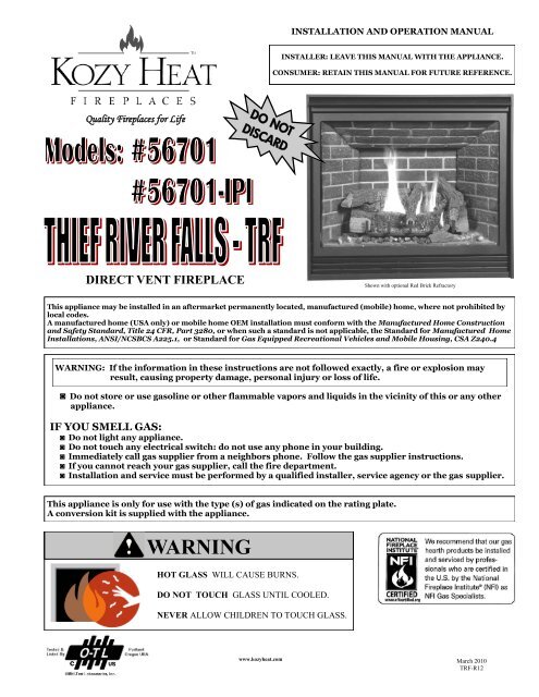
INSTALLATION AND OPERATION MANUALINSTALLER: LEAVE THIS MANUAL WITH THE APPLIANCE.CONSUMER: RETAIN THIS MANUAL FOR FUTURE REFERENCE.Quality Fireplaces for LifeDO NOTDISCARDDIRECT VENT FIREPLACEShown with optional Red Brick RefractoryThis appliance may be installed in an aftermarket permanently located, manufactured (mobile) home, where not prohibited bylocal codes.A manufactured home (USA <strong>only</strong>) or mobile home OEM installation must conform with the Manufactured Home Constructionand Safety Standard, Title 24 CFR, Part 3280, or when such a standard is not applicable, the Standard for Manufactured HomeInstallations, ANSI/NCSBCS A225.1, or Standard for Gas Equipped Recreational Vehicles and Mobile Housing, CSA Z240.4WARNING: If the information in these instructions are not followed exactly, a fire or explosion mayresult, causing property damage, personal injury or loss of life.◙ Do not store or use gasoline or other flammable vapors and liquids in the vicinity of this or any otherappliance.IF YOU SMELL GAS:◙ Do not light any appliance.◙ Do not touch any electrical switch: do not use any phone in your building.◙ Immediately call gas supplier from a neighbors phone. Follow the gas supplier instructions.◙ If you cannot reach your gas supplier, call the fire department.◙ Installation and service must be performed by a qualified installer, service agency or the gas supplier.This appliance is <strong>only</strong> for use with the type (s) of gas indicated on the rating plate.A conversion kit is supplied with the appliance.WARNINGHOT GLASS WILL CAUSE BURNS.DO NOT TOUCH GLASS UNTIL COOLED.NEVER ALLOW CHILDREN TO TOUCH GLASS.www.kozyheat.comMarch 2010TRF-R12
INTRODUCTIONRead this manual before installing or operating this appliance.Please retain this owner‟s manual for future reference.CONGRATULATIONS!We welcome you as a new owner of a Kozy Heat gas fireplace. Kozy Heat products aredesigned with superior components and materials and assembled by trained craftsmen whotake pride in their work. The burner and valve assembly are 100% test-fired and the completefireplace is thoroughly inspected before packaging to ensure that you receive a quality product.Our commitment to quality and customer satisfaction have remained the same for over 30years. We offer a complete line of gas and wood fireplaces, unique cabinets and stylishaccessories to compliment any décor. Adding a fireplace is one of the best ways to increase thevalue of your home and we are proud to offer a network of dealers throughout the country tohelp make your experience everything you imagine. We pride ourselves in being dedicated tonot <strong>only</strong> function and reliability, but customer safety as well. We offer our continual supportand guidance to help you achieve the maximum benefit and enjoyment from your Kozy Heatgas fireplace.Jim HussongPresidentDudley HussongBoard ChairmanHomeowner Reference InformationWe recommend that you record the following information about your fireplace.Model Name:______________________________ Date purchased/installed:___________________________Serial Number:____________________________Dealership purchased from:__________________Location on fireplace:_______________________________Dealer Phone:____________________________________Notes:___________________________________________________________________________________________________________________________________________________________________________________________________________________________________________________________________PAGE 1
INTRODUCTIONTABLE OF CONTENTSVENTING (cont.)Introduction and Homeowner Reference Information 1TABLE OF CONTENTSTable of Contents 2SAFETY INFORMATIONSafety Information 3FEATURESFeatures 4COMMONWEALTH OF MASSACHUSETTS INFORMATIONCommonwealth of Massachusetts Information 5SPECIFICATIONSFireplace Dimensions 6Clearances 6Components List 7Installation Overview 7Placement Clearance Requirements 7PREPARE THE FIREPLACENailing Flange Assembly & Installation 8Top Stand-Off Adjustment 8FRAMINGWall Enclosure Rough Opening 9Minimum Finished Opening Dimensions 9Vertical Terminations 10Horizontal Terminations 10TYPICAL INSTALLATION OPTIONSTypical Installation Options 11MANTEL REQUIREMENTSMantel Requirements 12GLASS FRAME ASSEMBLYGlass Frame Assembly Removal 12Glass Frame Assembly Installation 12FAN INSTALLATIONTMT-028 (<strong>56701</strong> <strong>only</strong>) Optional Fan Installation 13GAS LINE CONNECTIONGas Line Connection 14<strong>56701</strong> THERMOSTAT / WALL SWITCH / REMOTE<strong>56701</strong> Thermostat / Wall Switch / Remote 15VENTINGTop Vent Conversion Instructions 16-17Approved Venting 18Horizontal Vent System Clearances 18Min. / Max. Horizontal Vent System Information (Top Vent) 18Min. / Max. Horizontal Vent System Information (Rear Vent) 18Elbows 18Horizontal Termination Illustrations 19Minimum Venting for Corner Installation 20Vertical Terminations (Top &Rear Vent) 21Vertical Venting Illustrations 22Restrictor Installation 22Horizontal / Vertical Combination Venting 23700 Series Flex Vent Installation 24-25Termination Cap Location 26Vertical Cap Requirements 27LOG SET INSTALLATIONLog Set Installation 28-29CONTROL BOARDControl Board Removal 30Control Board Installation 31GRILL SETGrill Set Installation 32Grill Set Removal 32<strong>56701</strong> OPERATING INSTRUCTIONS<strong>56701</strong> Valve and Pilot Assembly Components 33<strong>56701</strong> Lighting and Shutdown Instructions 34-36<strong>56701</strong> Pressure Testing 37<strong>56701</strong>-<strong>IPI</strong> OPERATING INSTRUCTIONS<strong>56701</strong>-<strong>IPI</strong> Wiring Schematics 38<strong>56701</strong>-<strong>IPI</strong> Valve and Pilot Assembly Components 39<strong>56701</strong>-<strong>IPI</strong> Control Module Components 40<strong>56701</strong>-<strong>IPI</strong> Remote Control Information 41<strong>56701</strong>-<strong>IPI</strong> Information 42<strong>56701</strong>-<strong>IPI</strong> Remote Control Operation 43-45<strong>56701</strong>-<strong>IPI</strong> Lighting and Shutdown Instructions 46-47<strong>56701</strong>-RF Pressure Testing 48<strong>56701</strong>-<strong>IPI</strong> Error Codes 49FINALIZING THE INSTALLATIONBurner Tube Adjustment / Troubleshooting 50Restrictor Troubleshooting / Installation after Termination Completion 51MAINTENANCEMaintenance 52TROUBLESHOOTING<strong>56701</strong> Troubleshooting 53-55<strong>56701</strong>-<strong>IPI</strong> Troubleshooting 56-57CONVERSION KIT INSTRUCTIONSConversion Kit Instructions (<strong>56701</strong> <strong>only</strong>) 58-59Conversion Kit Instructions (<strong>56701</strong>-<strong>IPI</strong> <strong>only</strong>) 60-61REPLACEMENT PARTS LISTReplacement Parts List 62WARRANTYWarranty 63-64PAGE 2
SAFETY INFORMATIONThis fireplace has been tested to and complies with ANSI Z21.88a-2007·CSA 2.33a-2007·CSA P.4.1-02 “VENTED GAS FIREPLACE HEATERS”by OMNI-Test Laboratories, Portland, OR. Installation must conform with local building codes or in the absence of local building codes, with theNational Fuel Gas Code, ANSIZ223.1/NFPA 54 - Current Edition, or the Natural or Propane Installation Code, CSAB149.1Installation and repair should be done <strong>only</strong> by a qualified service person. The appliance should be inspected by aqualified service person before use. Annual inspection by a qualified service person is required to maintain warranty.More frequent cleaning may be required due to excessive lint from carpeting, bedding materials, etc. It is imperativethat control compartments, burners and circulation air passageways of the appliance be kept clean.If this appliance is installed directly on carpeting, tile or other combustible material other than wood flooring, theappliance shall be installed on a metal or wood panel extending the full width and depth of the appliance.Children and adults should be alerted to the hazards of high surface temperatures and should stay away to avoid burnsor clothing ignition.Young children should be carefully supervised when they are in the same room as the appliance. Toddlers, youngchildren and others may be susceptible to accidental contact burns. A physical barrier is recommended if there are atrisk individuals in the house. To restrict access to a fireplace or stove, install an adjustable safety gate to keep toddlers,young children and other at risk individuals out of the room and away from hot surfaces.Clothing or other flammable material should not be place on or near the appliance.Adequate accessibility clearances for servicing and proper operation must be maintained.This appliance must not share or be connected to a chimney flue serving any other appliance.Keep area around the appliance clear of combustible materials, gasoline and other flammable vapor and liquids.The flow of combustion and ventilation air must not be obstructed.Due to high temperatures the appliance should be located out of traffic and away from furniture and draperies.The glass front or any part removed for servicing the appliance must be replaced prior to operating the appliance.Work should be done by a qualified service technician.Clean glass <strong>only</strong> when cool and <strong>only</strong> with non-abrasive cleansers.Do not operate this appliance with the glass/frame assembly removed, cracked or broken. The glass assembly, Part#TRF-057T, shall <strong>only</strong> be replaced as a complete unit, as supplied by Hussong Mfg. Co., Inc. Replacement of the glassassembly must <strong>only</strong> be performed by a licensed or qualified service person. DO NOT SUBSTITUTE MATERIALS.Do not strike or slam glass assembly.Any safety screen or guard removed for servicing the appliance must be replaced prior to operating the appliance.Under no circumstances should any solid fuel (wood, coal, paper or cardboard etc.) be used in this appliance.Keep burner and control compartment clean.Do not use this fireplace if any part has been under water. Immediately call a qualified service technician to inspect thisappliance and to replace any part of the control system and any gas control which has been under water.PAGE 3
FEATURESSTANDARD FEATURESHigh efficiencyHigh quality lifetime glass26” x 35” (660 mm x 889 mm)Quick latch glass frame assemblyUpper grill / hood & lower grill (black)Accepts rigid pipe or Kozy Heat flexible vent systemPatented log designAutomatic fan kit (2) - 75 CFM*Minnesota Energy Code compliant to 50 pascals*Standard on <strong>56701</strong>-<strong>IPI</strong> models**Standard on <strong>56701</strong> modelsSAFETY FEATURESEach unit factory tested!Tested by OMNI - Test LaboratoriesSealed combustion chamberStanding pilot ignition**Intermittent or Standing pilot ignition*30-second delay pilot**Automatic pressure relief glass systemRequires no electricity to operate**(excluding fan)Battery back-up in the event of power failure*(excluding fan)Bedroom and mobile home approvedCanadian approved*Standard on <strong>56701</strong>-<strong>IPI</strong> models**Standard on <strong>56701</strong> modelsOPTIONAL FEATURESBrick refractory in various colorsAutomatic fan kit* with variable speed control ( (2) 75 CFM)Remote control* or thermostat remote controlWall mount thermostat / wireless wall mount thermostatDecorative full door faces in various styles and finishesMission design doors in various finishesVarious cabinet & flush surrounds*Standard on <strong>56701</strong>- <strong>IPI</strong> models**Standard on <strong>56701</strong> modelsWEIGHTFireplace Weight (as packaged for shipment)161 lbs. (73.03 kg)PAGE 4
COMMONWEALTH OF MASSACHUSETTS REQUIREMENTSNOTE: The following requirements reference various Massachusetts and national codes not contained in this manual.For all sidewall horizontally vented gas fueled equipment installed in every dwelling, building or structure used in whole or in part for residential purposes,including those owned or operated by the Commonwealth and where the side wall exhaust vent termination is less than (7) feet above finished grade in thearea of the venting, including but not limited to decks and porches, the following requirements shall be satisfied:INSTALLATION OF CARBON MONOXIDE DETECTORSAt time of installation of side wall horizontally vented gas fueled equipment, the installing plumber or gas-fitter shall observe that a hard wired carbon monoxidedetector with an alarm and battery back-up is installed on the floor level where the gas equipment is to be installed. In addition, the installing plumberor gas-fitter shall observe that a battery operated or hard wired carbon monoxide detector is installed on each additional level of the dwelling, building orstructure served by the side wall horizontal vented gas fueled equipment. It shall be the responsibility of the property owner to secure the services of qualifiedlicensed professionals for the installation of hard wired carbon monoxide detectors.In the event that the side wall horizontally vented gas fueled equipment is installed in a crawl space or attic, the hard wired carbon monoxide detector withalarm and battery back-up may be installed on the next adjacent floor level.In the event that the requirements of this subdivision can not be met at the time of completion of installation, the owner shall have a period of thirty (30) daysto comply with the above requirements; provided, however, that during said thirty (30) day period, a battery operated carbon monoxide detector with analarm shall be installed.APPROVED CARBON MONOXIDE DETECTORSEach carbon monoxide detector as required in accordance with the above provisions shall comply with NFPA 720 and be ANSI/UL 2034 listed and IAScertified.SIGNAGEA metal or plastic identification plate shall be permanently mounted to the exterior of the building at a minimum of eight (8) feet above grade directly in linewith the exhaust vent terminal for the horizontally vented gas fueled heating appliance or equipment. The sign shall read, in print no less the one-half inch(1/2) in size, “GAS VENT DIRECTLY BELOW. KEEP CLEAR OF ALL OBSTRUCTIONS”.INSPECTIONThe state or local gas inspector of the side wall horizontally vented gas fueled equipment shall not approve the installation unless, upon inspection, theinspector observes carbon monoxide detectors and signage installed in accordance with the provisions of 248 CMR 5.08 (2) (a) 1 through 4.EXEMPTIONSThe following equipment is exempt from 248 CMR 5.08 (2) (a) 1 through 4:The equipment listed in Chapter 10 entitled “Equipment Not Required To BeVented” in the most current edition of NFPA 54 as adopted by the Board; and Product Approved side wall horizontally vented gas fueled equipment installedin a room or structure separate from the dwelling, building or structure used in whole or in part for residential purposes.MANUFACTURER REQUIREMENTS - GAS EQUIPMENT VENTING SYSTEM PROVIDEDWhen the manufacturer of Product Approved side wall horizontally vented gas equipment provides a venting system design or venting system componentswith the equipment, the instructions provided by the manufacturer for installation of the equipment and the venting system shall include:Detailed instructions for the installation of the venting system design or the venting system components; andA complete parts list for the venting system design or venting system.MANUFACTURER REQUIREMENTS - GAS EQUIPMENT VENTING SYSTEM NOT PROVIDEDWhen the manufacturer of Product Approved side wall horizontally vented gas equipment does not provide the parts for venting the flue gases, but identifies“special venting systems”, the following requirements shall be satisfied by the manufacturer:The referenced “special venting systems” instructions shall be included with the appliance or equipment installation instructions and;The “special venting systems” shall be Product Approved by the Board, and the instructions for that system shall include a parts list and detailedinstallation instructions.A copy of all installation instructions for all Product Approved side wall horizontally vented gas fueled equipment, all venting instructions, all parts lists forventing instructions, and/or all venting design instructions shall remain with the appliance or equipment at the completion of the installation.PAGE 5
SPECIFICATIONSFIREPLACE DIMENSIONSLETTER KEY A B C D E F G H I J KDESCRIPTION Height Width Back Width Depth OpeningWidthGlass FrameHeightStand-offHeightTop to UpperVent CenterUnit Top toBack VentTopRear VentCenter to TopFloor to RearVent CenterFIREPLACEDIMENSIONSINCHES 34-1/2 40-3/4 22-1/2 15-3/4 36 26 3-1/2 6-3/4 3-1/2 6-1/2 27-7/8MILLIMETERS 876 1035 572 400 914 660 89 171 89 165 708WARNING: Top stand-off bracket must be attached to fireplace. Do not remove. Stand-off bracket is not load bearing.Non-combustible zone: Stand-off provides 3-1/2” (89mm) minimum clearance to header. Use <strong>only</strong> non-combustible material inthis area for entire width of fireplace. Do not use wood, sheetrock etc. in this zone. Other clearances apply. All clearances mustbe maintained.I3-1/2”(89 mm)J6-1/2”(165 mm)G3-1/2”(89 mm)K27-7/8”(708 mm)A34-1/2”(876 mm)F26”(660 mm)STAND-OFFE36”(914 mm)FIREPLACE FRONTFIREPLACE FRONTB40-3/4”(1035 mm)LEFT SIDERIGHT SIDEC22-1/2”(572 mm)GAS LINE HOLE5-1/2”(140 mm)5-3/4”(146 mm)GAS LINE HOLEELECTRICALACCESSD15-3/4”(400 mm)H6-3/4”(171 mm)2-1/8”(54 mm)THERMOSTAT WIREACCESS HOLEFigure 6a3-3/8”(86 mm)9-1/4”(235 mm)CLEARANCESTop of unit face to framingFrom unit left & right sides & backTo flooringUnit top to ceilingUnit side to adjacent sidewallUnit front to combustiblesTop of unit to 3/4” (19 mm) trimMantel 8” (203 mm) deep from top of fireplace3-1/2” (89 mm)1/2” (13 mm)0” (0 mm)31” (787 mm)0” (0 mm)36” (914 mm)6” (152 mm)8” (203 mm)PAGE 6
SPECIFICATIONS#<strong>56701</strong> COMPONENTS LISTPART NUMBERDESCRIPTIONTRF-770 Millivolt Board Assembly700-203 Manual Gas Shut-off ValveTRF-030 Burner CoverTRF-035 Burner TubeTRF-500A Log PackageTRF-057T Glass Frame AssemblyOCK-S53A LP Conversion Kit600-083 Receptacle / Speed Control Assembly900085 4” Restrictor Plate500-TRF 3 pc. Grill Assembly#<strong>56701</strong>-<strong>IPI</strong> COMPONENTS LISTPART NUMBERDESCRIPTIONTRF-600-<strong>IPI</strong> Control Board Assembly700-203 Manual Gas Shut-off ValveTRF-030 Burner CoverTRF-035 Burner TubeTRF-500A Log PackageTRF-057T Glass Frame AssemblyOCK-A53L-<strong>IPI</strong> LP Conversion Kit600-002 Double Receptacle Assembly900085 4” Restrictor Plate500-TRF 3 pc. Grill Assembly<strong>IPI</strong>-028 <strong>IPI</strong> Fan Kit700-208 Remote ControlINSTALLATION OVERVIEWNOTE: The qualified installer should follow the procedure best suited for the installation.1. Frame an opening for the fireplace, allowing for vent installation (top or rear) and type of installation (corner or flat wall application).2. If masonry (optional) is used, prepare foundation for the masonry load. A lintel is required to support the added weight above fireplace.3. Attach nailing flanges to fireplace.4. Insert fireplace into framing.5. Install hearth (if applicable).6. Complete gas line installation.7. Complete electrical hook-up. Install any standard or optional electrical components at this time.8. Complete venting installation.9. Secure fireplace to flooring through holes in outer box bottom and to framing with nailing flanges. Verify all clearances at this point.10. Install facing material, mantel or cabinetry, allowing room for optional full face doors, if applicable.11. Install optional refractory.12. Install logs.13. Install grills and optional decorative doors / faces.14. Verify proper operation of fireplace and all components.PLACEMENT CLEARANCE REQUIREMENTSThis fireplace must be installed on a level surface capable of supporting the fireplace and venting.Fireplace must be placed directly on wood or non-combustible surface (not linoleum or carpet) extending entire depth and width offireplace.Due to high surface temperatures, fireplace should be located out of traffic and away from furniture and draperies.This fireplace may be installed in a bedroom.Please be aware of the large amount of heat this fireplace will produce when determining a location.PAGE 7
NAILING FLANGE ASSEMBLY & INSTALLATIONWhen installed, nailing flanges provide the minimum 1/4” (6 mm) clearance from fireplace sides.1. Remove (4) nailing flanges from fireplace sides.PREPARE THE FIREPLACE2. With the 1/4” (6 mm) stand-offs on nailing flanges facing away from fireplace, align nailing flange with holes on outside corners offireplace. Secure with screws (provided with components packet) through slots in nailing flanges.3. Bend perforation on nailing flange until parallel with fireplace face. Do not bend toward fireplace face.4. Position framing stud against 1/4” (6 mm) stand-off located on backside of nailing flange and secure with nails or screws.NOTE: Depending on facing material, nailing flanges can be adjusted forward or backwards up to 1/2” (13 mm).CAUTION: Never permanently remove these assemblies from fireplace. They must be secured in place regardless of finish material used.1/4” (6mm)CLEARANCESTAND-OFFNAILING FLANGESINSTALLEDNAILING FLANGE1/4” (6mm)CLEARANCEFRAMING STUDAS SHIPPEDFRONT VIEWFRAMING STUDNAILING FLANGETOP VIEWFigure 8aTOP STAND-OFF ADJUSTMENTThe top stand-off is adjustable to accommodate finish material thickness (non-combustible material <strong>only</strong>).TO ADJUST: Loosen screws at fireplace top, slide top stand-off to desired position, retighten screws.TOP STAND-OFF ADJUSTMENT SLOTSFigure 8b8
FRAMINGWALL ENCLOSURE ROUGH OPENINGIMPORTANT: Framing dimensions should allow for wall covering thickness and fireplace facing materials. If using a hearth, adjustrough opening size as necessary to maintain at least minimum clearance requirements.IMPORTANT: NON-COMBUSTIBLE FACING MATERIAL MAY BE APPLIED OVER (BUT NOT DIRECTLY TO) FIREPLACE FACE. THISWILL PREVENT FACING MATERIAL FROM FALLING OFF DUE TO HEAT EXPANSION. DO NOT OBSTRUCT THE FLOWOF VENTILATION AIR.MINIMUM FINISHED OPENING DIMENSIONS(APPLIES TO BOTH HORIZONTAL AND VERTICAL VENTING TERMINATIONS)38-1/4”(972 mm) High x 41-1/4”(1084 mm) Wide x 16-1/4” (413 mm) Deep.1/2” (13 mm) clearance at back and sides of fireplace must be maintained.NOTE: Provide adequate clearance in front of fireplace to operate lower grill, open and close optional decorative doors / full door faces,access components, installation of gas line, fan, etc.WARNING: DO NOT OBSTRUCT UPPER AND LOWER GRILL OPENINGS. ROOM AIR ENTERS THROUGH LOWER PASSAGE, IS HEATEDAND EXITS THROUGH UPPER PASSAGE. BLOCKING THESE PASSAGES MAY RESULT IN OVERHEATING, CREATING APOTENTIALLY HAZARDOUS SITUATION.38-1/4”(972 mm)41-1/4”(1084 mm)16-1/4”(413 mm)Figure 9aPAGE 9
FRAMINGDetermine exact position of your fireplace, including hearth height, width, and depth, (if applicable). If possible, place fireplace in such amanner that vent termination will be placed between two studs, eliminating the need for additional framing.If masonry is to be used (optional), prepare the necessary foundation for the masonry load. When masonry construction is being used, alintel must be used over top of fireplace to support the added weight.Build hearth to desired size and height. If a hearth extension is desired, combustible material may be used.NOTE: Consider height of hearth finish material (stone, brick, etc.) when building fireplace platform. The bottom of fireplace must belevel with finished hearth to allow for lower grill operation and proper fit of optional decorative full door faces.WARNING: Install fireplace on hard metal or wood surface extending the full width and depth of fireplace.Minimum platform size: 40-3/4” (1035 mm) wide x 15-3/4” (400mm) deep.FIRE HAZARD: Do NOT install directly on carpeting, vinyl, or any combustible material other than wood.IMPORTANT: Vent cap location must be in compliance with guidelines on page #26 of this manual.VERTICAL TERMINATIONSFollow vent pipe manufacturer‟s installation instructions for vertical terminations. A minimum 1” (25 mm) clearance on all sides of verticalvent pipe must be maintained.HORIZONTAL TERMINATIONSFollow vent pipe manufacturer‟s installation instructions for horizontal terminations. Include required 1-1/2” (38 mm) top clearance and1” (25 mm) sides and bottom clearances for approved rigid vent systems and the Kozy Heat #700 series flexible vent system.MINIMUM HORIZONTAL FRAMING DIMENSIONS(REAR VENT APPLICATIONS)VENT PIPE TOP (A)FRAMED OPENING TOP (B)RIGID PIPE 31” (787 mm) 32-1/2” (826 mm)MINIMUM HORIZONTAL FRAMING DIMENSIONS(TOP VENT APPLICATIONS)VENT PIPE TOP (A)FRAMED OPENING TOP (B)RIGID PIPE 44-1/8” (1121 mm) 45-5/8” (1159 mm)FLEX PIPE 52-1/2” (1333 mm) 53-1/2 (1359 mm)MINIMUM HORIZONTAL FRAMING DIMENSIONS(CORNER INSTALLATIONS)VENT PIPE TOP (A)FRAMED OPENING TOP (B)RIGID PIPE 44-1/8” (1121 mm) 45-5/8” (1159 mm)Figure 10aCAUTION: Cold air transfer area. The surrounding fireplace chase must comply with all clearances as outlined in this manual and beconstructed in compliance with local building codes. Outside walls should be insulated to prevent cold air from entering room.CAUTION: Due to high temperatures, this fireplace should be located out of traffic areas and away from furniture and draperies.PAGE 10
TYPICAL INSTALLATION OPTIONSREAR VENT VERTICALTOP VENT16-1/4”(413 mm)27-1/8”(689 mm)1” (25 mm)Clearance41-1/4”(1048 mm)41-1/4”(1048 mm)REAR VENT HORIZONTAL1” (25 mm)Clearance-Sides1/2” (13 mm)clearance16-1/4”(413 mm)1/2” (13 mm)Clearance41-1/4”(1048 mm)CORNER1/2” (13 mm)Clearance at back corners27-1/8”(689 mm)39-1/8”(994 mm) 55-1/4”(1403 mm)Figure 11aIMPORTANT: 1/2” (13 mm) wall materials included in dimensions where applicable. Modifyminimum opening if necessary to accommodate finish material thickness.PAGE 11
NON-COMBUSTIBLE ZONE:MANTEL REQUIREMENTSRigid pipe: 1-1/2” (38 mm) above elbow for entire width and depth (behind header) of fireplace.#700 series flexible venting: 1” (25 mm) above elbow for entire width and depth (behind header) of fireplace.14"356mm14"(356mm)12"(305mm)10" (254mm)8" (203mm)12"305mm 10"254mm 8"203mm6"152mm3 4 "19mmFigure 12aGLASS FRAME ASSEMBLYCAUTION: TO PREVENT GLASS FRAME ASSEMBLY FROM FALLING FROM FIREPLACE AND BECOMING DAMAGED, FOLLOW THESEINSTRUCTIONS EXACTLY WHEN REMOVING AND INSTALLING GLASS FRAME ASSEMBLY.REMOVE GLASS FRAME ASSEMBLY1. Locate spring-loaded handles securing glass frame assembly at top & bottom of firebox.2. Pull bottom handles out and „down‟ to release glass frame assembly bottom.3. Pull top handles out and „up‟ to release glass frame assembly top.INSTALL GLASS FRAME ASSEMBLY1. Place glass frame assembly onto fireplace front.2. Pull top handles out and „down‟ to secure glass frame assembly top.3. Pull bottom handles out and „up‟ to secure glass frame assembly bottom.Pull latches „out‟ and „up‟ to release glass frameassembly top.Pull latches „out‟ and „down‟ to attach glassframe assembly top.Pull latches „out‟ and „down‟ to release glassframe assembly bottom.Pull latches „out‟ and „up‟ to attach glass frameassembly bottom.Figure 12bPAGE 12
OPTIONAL FAN INSTALLATION (<strong>56701</strong> <strong>only</strong>)INSTALLATION OF THIS FAN SHOULD BE DONE ONLY BY A QUALIFIED INSTALLERWARNING: MAKE SURE HOUSEHOLD BREAKER IS SHUT OFF PRIOR TO WORKING ON ANY ELECTRICAL LINES.WARNING: THIS APPLIANCE IS EQUIPPED WITH A THREE-PRONG (GROUNDING) PLUG FOR PROTECTION AGAINST SHOCK HAZARD ANDSHOULD BE PLUGGED DIRECTLY INTO A PROPERLY GROUNDED THREE-PRONG RECEPTACLE. DO NOT CUT OR REMOVEGROUNDING PRONG FROM THIS PLUG.IMPORTANT: If installing a fan, it is easier to complete prior to connecting millivolt board to gas supply. Wiring must be done before enclosing fireplacesides. An electrical box and romex connector are pre-installed on a removable panel on right side of fireplace. A receptacle / speed controlassembly and (3) wire nuts are included in fireplace components packet.NOTE: Code approved line voltage wiring 14 gauge or better must be used when wiring this assembly. Refer local electrical codes for specific requirements.NOTE: This appliance must be electrically grounded and connected in accordance with local codes, or in the absence of local codes, with the National ElectricalCode, ANSI/NFPA 70 Current Edition, or the Canadian electrical Code CSA C22.1.NOTE: This fan will not operate unless speed control has been turned „ON‟ and sufficient heat has been applied to temperature control switch. The fan willturn „ON‟ and „OFF‟ automatically as fireplace heats and cools. Adjust fan to desired speed while it is running.Optional fan kit #TRF-028 includes:(2) 75 CFM fan with temperature control switch and 4 ft. (1219 mm) fan cord(4) 1/4” nuts1. Remove upper hood, upper louver & lower grill, if installed. Page 32.2. Remove glass assembly. Page 123. Insert fans through lower grill opening on left side of gas valve. Push to back of fireplace. Align mounting slots in fan brackets withmounting studs. Secure with nuts.4. From inside lower right grill opening, loosen screw securing removable access panel (with electrical box & romex connector installed).Remove panel.5. Insert 115V wiring (with ground) through romex connector and wire to speed control / receptacle assembly matching black (hot), white(neutral), and green (ground) wires to corresponding wires on speed control / receptacle assembly.6. Secure speed control / receptacle assembly to electrical box with (2) screws provided.7. Re-install electrical access panel. Tighten screw.8. Attach temperature control switch to bottom of firebox.9. Plug cord into electrical box receptacle.10. Turn speed control counter-clockwise until it „clicks‟. This is the „OFF‟ position.11. Turn speed control „ON‟ by turning knob clockwise past the „click‟ - this is the highest setting.12. Re-install glass assembly, lower grill, upper louver & upper hood.TEMPERATURE CONTROL SWITCH POSITIONBefore adjusting temperature control switch, unplug 3-prong plugon fan cord from receptacle. Adjust position of temperaturecontrol switch to a warmer location under firebox to turn fan„ON‟ sooner or move it to a cooler location under firebox to turnfan „ON‟ later. The fan will turn on when sensor in temperaturecontrol switch reaches 110° F and will turn „OFF‟ when sensorreaches 90° F. After adjustment, plug 3-prong plug on fan cordinto receptacle.Temperature Switch:Incoming wiringElectrical Box60Hz110V-120VSpeed Control /Receptacle AssemblyFigure 13aPAGE 13
GAS LINE CONNECTIONGAS CONVERSIONThis fireplace is manufactured for use with Natural Gas. An LP conversion kit, is included with this fireplace. Follow instructions includedwith conversion kit if converting to LP gas.ATTENTION: The conversion shall be carried out in accordance with the requirements of the provincial authorities having jurisdiction andin accordance with the requirements of the ANSI Z223.1 installation code.CAUTION: Installation of the gas line must <strong>only</strong> be done by a qualified person in accordance with local building codes, if any.If not, follow ANSI 223.1.Commonwealth of Massachusetts: Installation must be done by a licensed plumber of gas fitter.NOTE: A listed (and Commonwealth of Massachusetts approved) 12” (13 mm) T- handle manual shut-off valve and flexible gasconnector (included) are connected to the 1/2” (13 mm) control valve inlet. If substituting for these components, pleaseconsult local codes for compliance.NOTE: This fireplace is equipped with a 3/8”(10 mm) x 18” (457 mm) long flexible gas connector and manual shut-off valve. Thegas line should be run to the point of connection where the shut-off valve and flexible gas line will connect.NOTE: The appliance and its individual shutoff valve must be disconnected from the gas supply piping system during any pressuretesting of that system at pressures in excess of ½ psi.NOTE: The appliance must be isolated from the gas supply piping system by closing its individual manual shut-off valve duringany pressure testing of the gas line at test pressures equal to or less than ½ psi (3.5 kPa).NOTE: For high altitude installations, consult the local gas distributor or the authority having jurisdiction for proper ratingmethods.IMPORTANT: The efficiency rating of this appliance is a product of thermal efficiency rating determined under continuous operatingconditions and was determined independently of any installed system.<strong>56701</strong> <strong>56701</strong>-<strong>IPI</strong>NATURAL GAS LP GAS NATURAL GAS LP GASMINIMUM INLET GAS PRESSURE5.0 inches W.C.(7.0 W.C. recommended)11.0 inches W.C.(recommended)5.0 inches W.C.(7.0 W.C. recommended)11.0 inches W.C.(recommended)MAXIMUM INLET GAS PRESSURE 10.5 inches W.C. 13.0 inches W.C. 10.5 inches W.C. 13.0 inches W.C.MANIFOLD PRESSURE (HI) 3.5 inches W.C 10.0 inches W.C. NA NAMANIFOLD PRESSURE (LO) 1.1 inches W.C. 6.3 inches W.C NA NAORIFICE SIZE #38 #.0625 #38 #.0625INPUT BTU/hr. 28,000 28,000 28,000 28,000MINIMUM INPUT BTU/hr. 20,000 21,000 20,000 21,000EFFICIENCY 71.90% 74% 71.90% 74%PAGE 14
THERMOSTAT / WALL SWITCH / REMOTE (<strong>56701</strong> <strong>only</strong>)If desired, a thermostat (wireless style also available), wall switch, or remote control assembly may be used to turn fireplace „OFF‟ and„ON‟. Only ONE of these may be installed. Follow instructions included with chosen assembly.NOTE: INSTALLATION OF THERMOSTAT OR WALL SWITCH SHOULD ONLY BE DONE BY A QUALIFIED INSTALLER.CAUTION: DO NOT CONNECT HIGH VOLTAGE (115V) WIRE TO GAS VALVE!Remote Control Wiring DiagramThermostat Wiring DiagramOPTIONAL: Disconnect ON/OFFrocker switch wiresfrom back of gas valve.Figure 15aFigure 15bWALL SWITCH / THERMOSTAT:Run low-voltage (thermostat) wires from terminals on gas valve to desired location of wall switch or thermostat.Attach appropriate connectors to wall switch / thermostat wires and connect to top and bottom terminals marked TH/TPTH on gas valve.REMOTE CONTROL:Follow instructions included with remote control.IMPORTANT: If ON/OFF rocker switch wires are not disconnected, the ON/OFF rocker switch on millivolt board must be in „OFF‟position for proper operation of any of these components.IMPORTANT: If rocker switch is „ON‟, fireplace burner will operate until it is turned „OFF‟ by rocker switch. A wall switch,thermostat, or remote control will not turn fireplace „OFF‟ when it has been turned „ON‟ by the rocker switch.Fireplace must be turned „ON‟ and „OFF‟ by same method.Example: If fireplace is turned „ON‟ by remote control, it must be turned „OFF‟ by remote control.IMPORTANT: The insulated cover included with remote control must be placed over remote receiver to prevent overheating.PAGE 15
VENTING (Top vent conversion instructions)REMOVE BACK VENT COLLARSNOTE: All components removed from fireplace back vent will be re-installed for top venting.123Figure 16a1. Remove back cover and attachment screw .2. Remove 6-5/8 combustion air intake collar and (4) screws.3. Remove 4” exhaust collar and (6) screws.REMOVE TOP COMBUSTION AIR INTAKE & EXHAUST COLLARS123Remove45Figure 16b1. Remove top cover and screw.2. Remove heat shield cover (w/ knockout) and screw.3. Using tin snips, remove center knockout section.4. Remove 6-5/8” combustion air intake cover and (4) screws.5. Remove exhaust cover and (6) screws.PAGE 16
VENTING (Top vent conversion instructions cont.)INSTALL EXHAUST & COMBUSTION AIR INTAKE COLLARS TO FIREPLACE TOP123Tab4TabsFigure 17a1. Install 4” exhaust collar to fireplace top. Secure with (6) screws previously removed.2. Install 6-5/8” combustion air intake collar to fireplace top. Secure with (4) screws previously removed.3. Insert tab on heat shield cover (center previously removed) into slot on fireplace top.4. Insert tabs on top cover plate into slots at top of fireplace. Secure with (1) screw previously removed .INSTALL COVER PLATES TO FIREPLACE BACKWARNING: Cover plates must be installed on back of fireplace. Do not proceed with fireplace installation until this procedure iscompleted. Follow instructions below.12 3TabsFigure 17b1. Install 4” exhaust cover plate to fireplace back. Secure with (6) previously removed screws.2. Install combustion air intake cover to fireplace back. Secure with (4) previously removed screws.3. Insert tabs on outer cover into slots in fireplace back. Secure cover top with (1) previously removed screw.PAGE 17
VENTINGIMPORTANT: Consult the local and national installation codes to assure adequate combustion and ventilation air is available.IMPORTANT: Flame height and appearance will vary depending upon venting configuration and type of fuel used.Venting requirements apply to both Natural and LP gas.Refer to vent systems manufacturer's installation manual for complete installation instructions.Installation must conform with venting requirements and restrictions as outlined in this manual.APPROVED VENTINGSimpson Dura-Vent DV-GS 4” x 6-5/8” direct vent system (horizontal and vertical terminations).Ameri-Vent Direct Chimney System 4” x 6-5/8” (horizontal and vertical terminations).Kozy Heat #700 series flexible vent system (horizontal terminations).Metal Fab 4” x 6-5/8” direct vent chimney system (horizontal and vertical terminations).ICC 4” x 6-5/8” direct vent chimney system (horizontal and vertical terminations).Security 4” x 6-5/8” direct vent chimney system (horizontal and vertical terminations).Amerivent / American Metal 4” x 6-5/8” direct vent chimney system (horizontal and vertical terminations).Selkirk Metalbestos 4” x 6-5/8” direct vent chimney system (horizontal and vertical terminations).HORIZONTAL VENT SYSTEM CLEARANCESTOP BOTTOM SIDESALL APPROVED VENTING 1-1/2 inches (38 mm) 1 inch (25 mm) 1 inch (25 mm)HORIZONTAL TERMINATIONS (top vent)NOTE: Flange on top stand-off must be bent upwards to a 90˚ angle when top venting.MINIMUM: 90° elbow + 6” (152 mm) horizontal + termination cap.MAXIMUM: 90° elbow + 14 ft. (4.27 m) + termination cap.HORIZONTAL TERMINATIONS (rear vent)MINIMUM: 6” (152 mm) horizontal + termination cap.MAXIMUM: 24” (610 mm) horizontal + termination cap.RESTRICTORA restrictor is included in fireplace components packet.Each installation is unique and affected by various factors including venting configuration, altitude and climate. Therefore, after fireplaceinstallation is complete a restrictor may be required or may need to be removed or modified.Please refer to page 22 for installation instructions if installing restrictor in conjunction with venting.Page 51 has information on restrictor recommendations depending on burner flame appearance and instructions on installation after venting iscompleted.ELBOWSFor each additional 90° elbow used after first elbow, 3 ft. (914 mm) must be subtracted from maximum allowed venting. For each 45° elbowused, 1-1/2 ft. (457 mm) must be subtracted from maximum venting allowed.NOTE: (2) 45° degree elbows may be used in place of (1) 90° elbow.PAGE 18
VENTINGNOTE: Horizontal sections require 1/4” (6 mm) rise for every 12” (305 mm) of travel.NOTE: Flange on top stand-off must be bent upwards to a 90˚ angle when top venting.NOTE: Page 22 has information on restrictor installation in conjunction with venting installation. Page 51 has information onrestrictor recommendations depending on burner flame appearance and instructions on installation after venting is completed.IMPORTANT: If top venting, follow instructions on pages 16-17 to convert fireplace from rear vent ready to top vent ready.CAUTION: This gas appliance must not be connected to or joined with any other chimney flue serving another appliance.HORIZONTAL TERMINATIONS (top vent)Max: 14 ft. (4.27m)Min: 6” (152 mm)90° ELBOWTERMINATION CAPFigure 19aHORIZONTAL TERMINATIONS (rear vent)Min: 6” (152 mm)Max: 24” (610 mm)TERMINATION CAPFigure 19bPAGE 19
HORIZONTAL TERMINATIONSVENTINGNOTE: Horizontal sections require 1/4” (6 mm) rise for every 12” (305 mm) of travel.NOTE: Flange on top stand-off must be bent upwards to a 90˚ angle when top venting.NOTE: Page 22 has information on restrictor installation in conjunction with venting installation. Page 51 has information onRestrictor recommendations depending on burner flame appearance and instructions on installation after venting is completed.IMPORTANT: If top venting, follow instructions on pages 16-17 to convert fireplace from rear vent ready to top vent ready.CAUTION: This gas appliance must not be connected to or joined with any other chimney flue serving another appliance.TYPICAL CORNER INSTALLATION90° elbow + horizontal pipe + termination cap.VENTING DIMENSIONS FOR MINIMUM CORNER INSTALLATIONSVent Opening Dimensions: Refer to vent pipe manufacturer's instructionsPIPE90° ELBOWHORIZONTALTERMINATION CAPFigure 20aPAGE 20
VENTINGVERTICAL VENT SYSTEM CLEARANCESTOP BOTTOM SIDESALL RIGID PIPE APPLICATIONS 1 inch (25 mm) 1 inch (25 mm) 1 inch (25 mm)KOZY HEAT #700 SERIESDO NOT USE FOR VERTICAL TERMINATIONSVERTICAL TERMINATIONS (top vent)MAXIMUM: 33 ft. (10.06m) + cap.NOTE: Flange on top stand-off must be bent upwards to a 90˚ angle when top venting.VERTICAL TERMINATIONS (rear vent)MINIMUM: 90˚ elbow +14” ( 356mm) + cap.MAXIMUM: 90˚ elbow + 22 ft. (6.71m) + cap.RESTRICTORA restrictor is included in fireplace components packet.Each installation is unique and affected by various factors including venting configuration, altitude and climate. Therefore, afterfireplace installation is complete a restrictor may be required or may need to be removed or modified.Please refer to page 22 for installation instructions if installing restrictor in conjunction with venting.Page 51 has information on restrictor recommendations depending on burner flame appearance and instructions on installation afterventing is completed.HORIZONTAL & VERTICAL COMBINATION TERMINATIONS (top vent)MAXIMUM: 10 ft. (3.05) horizontal + 20 ft. (6.10 m) vertical + cap. 30 ft (9.14m) total.NOTE: Flange on top stand-off must be bent upwards to a 90˚ angle when top venting.ELBOWSFor each additional 90° elbow used after first elbow, 3 ft. (914 mm) must be subtracted from maximum allowed venting.For each 45° elbow used, 1-1/2 ft. (457 mm) must be subtracted from maximum venting allowed.NOTE: (2) 45° degree elbows may be used in place of (1) 90° elbow.PAGE 21
VENTINGVERTICAL VENTING (rear vent)MAXIMUM VERTICAL VENTING (top vent)TERMINATION CAPMIN. 14”(356 mm)MAX. 22 ft (7.71m)TERMINATION CAPMAX. 33 ft.(10.06 m)90° ELBOWFigure 22aFigure 22bCAUTION: This gas appliance must not be connected to or joined with any other chimney flue serving another appliance.NOTE: Flange on top stand-off must be bent upwards to a 90˚ angle when top venting.RESTRICTOR INSTALLATIONTO BE USED AT INSTALLER DISCRETION.Large RestrictorRemove tab (s) tocreate small restrictorBend tabs to approx. 80 degreeangles to create tension to holditself in place when installed.Slide restrictor into exhaust pipe on top of fireplace with tabspointing towards you prior to attaching venting.Figure 22cNOTE: Page 51 has information on restrictor recommendations depending on burner flame appearance and instructions on installationafter venting is completed.PAGE 22
HORIZONTAL / VERTICAL COMBINATIONVENTINGNOTE: Page 22 has information on restrictor installation in conjunction with venting installation.Page 51 has information on restrictor recommendations depending on burner flame appearance and instructions oninstallation after venting is completed.Horizontal sections require 1/4” (6 mm) rise for every 12” (305 mm) of travel.Flange on top stand-off must be bent upwards to a 90˚ angle when top venting.For each additional elbow used after first elbow, 3 ft. (914 mm) must be subtracted from maximum venting allowed. Foreach 45° elbow used, 1-1/2 ft. (457 mm) must be subtracted from maximum venting allowed.(2) 45° degree elbows may be used in place of (1) 90° elbow.TERMINATION MUST BEWITHIN SHADED AREA.HORIZONTAL / VERTICALCOMBINATION20‟ (6.10 m) VERTICAL10‟ (3.05 m) HORIZONTALFigure 23aCAUTION: This gas appliance must not be connected to or joined with any other chimney flue serving another appliance.IMPORTANT: A WALL THIMBLE PASS-THRU MUST BE USED ON ALL HORIZONTAL VENT RUNS THAT PASS THROUGHEITHER INTERIOR OR EXTERIOR WALLS. FOLLOW VENT SYSTEM MANUFACTURER‟S INSTRUCTIONS.PAGE 23
VENTING#700 SERIES DIRECT VENT TERMINATION KIT(S) INSTALLATIONIMPORTANT: The flex pipe is permanently attached to the exterior plate. DO NOT ATTACH #745 or #718 termination kit to fireplace(or extension kit ) until it has passed through the wall. Install termination plates to outside wall exterior.HORIZONTAL TERMINATIONS Refer to illustration on following page.IF TERMINATING AGAINST VINYL SIDING, A VINYL SIDING PROTECTOR, INCLUDED WITH #718 AND #745 DIRECTVENT KITS, MUST BE USED. FOLLOW INSTRUCTIONS INCLUDED.ATTENTION: Horizontal Top Vent Terminations using Kozy Heat #700 series Flexible Vent System must install # 923-F Kozy Heat FlexVent System Adaptor.CAUTION: This gas appliance must not be connected to a chimney flu serving another type of appliance.NOTE: Page 22 has information on restrictor installation in conjunction with venting installation. Page 51 has information on restrictorrecommendations depending on burner flame appearance and instructions on installation after venting is completed.1. If your vent system application does not require an extension kit, proceed to step #7.2. If your vent system application will require one or more extension kits (Part #746), proceed with following steps. Each #746 extensionkit contains enough 4” & 7” flexible aluminum to extend chimney an additional 6‟ (1.83 m).3. Gently stretch 4” & 7” flexible aluminum pipes on termination kit (#745 or #718) and on each extension kit (if used) length requiredfor installation.IMPORTANT: DO NOT STRETCH EXTENSION KIT- #746 BEYOND 6‟ (1.83 m). DO NOT STRETCH BEYOND WHAT IS REQUIRED - IT IS VERYDIFFICULT TO RECOMPRESS FLEX PIPES ONCE STRETCHED.4. Place a bead of sealant outside 4” flex pipe collar (C) (end with EXTERNAL lip), sliding it inside 4” pipe on top of fireplace (D).Secure with 3 evenly spaced screws.5. Place a bead of sealant inside 7” flex pipe collar (E) (end with INTERNAL lip), sliding it over 7” pipe on top of fireplace (F). Securewith 3 evenly spaced screws.6. If additional extension kits are required, repeat steps #4 - #5, placing 4” & 7” pipes onto previous extension kit.OPTIONAL: Place insulation between 7” pipe and wall studs.7. With spacer legs toward wall, slide interior firestop (H) over 7” pipe and attach to interior wall (over wall materials).NOTE: Attachment brackets are included with termination kit. These optional brackets should be screwed or nailed (not provided)onto top and bottom of 9-1/2” (241 mm) H x 9-1/2” (241 mm) W opening on exterior of house. The termination plates then fitbetween these brackets. Using screws provided, secure brackets to termination box (A). Attach vinyl siding protector (G).8. Apply a liberal bead of exterior sealant around outer edge of termination box (A), placing assembly through opening in exterior wall.Place screws through four slots (B), securing it in place.9. Gently pull 4” & 7” pipes down to top of extension kit, or top of fireplace if no extension kits were used.10. Place a bead of sealant outside 4” flex pipe collar (C) and slide it into 4” pipe on extension kit or top of fireplace (D).Secure with 3 evenly spaced screws.11. Place a bead of sealant inside 7” flex pipe collar (E) and slide it over 7” pipe on extension kit or top of fireplace (F). Secure with 3evenly spaced screws.ILLUSTRATION ON FOLLOWING PAGE.PAGE 24
VENTINGFLEXIBLE #700 SERIES cont.ABCDEFGHTERMINATION BOXSLOTS IN EXTERIOR WALL PLATE4” FLEX PIPE COLLAR4” PIPE ON FIREPLACE OR EXTENSION KIT7” FLEX PIPE COLLAR7” PIPE ON FIREPLACE OR EXTENSION KITVINYL SIDING PROTECTORINTERIOR FIRESTOPAGBEHCFDFigure 25aIMPORTANT: If top venting, follow instructions on pages 16-17 to convert fireplace from rear vent ready to top vent ready.PAGE 25
1. Terminations against vinyl siding must use a vinyl siding protector. Follow instructions included.2. DO NOT RECESS TERMINATION KIT INTO OUTSIDE BUILDING MATERIALS - i.e.: brick, stone, siding, etc. If necessary,extend framing so that termination kit will be exposed once building materials are installed.3. Vent termination must not be located where it will become plugged by snow or other material. The flow of combustion and ventilationair must be not obstructed.LOCATION CLEARANCESTERMINATION VENT CAP LOCATIONThis gas appliance must not be connected to a chimney serving any other appliance.A. Above grade, veranda, porch, deck, balcony - 12" (305 mm).B. Operable window or door - CANADA: 12" (305 mm). US: 9” (229 mm).C. Permanently closed window* - 12" (305 mm) (recommended to prevent condensation on window).D. Ventilated soffit* - 24" (610 mm).E. Unventilated soffit* - 12" (305 mm).F. Outside corner* - 12" (305 mm).G. Inside corner* - 12” (305 mm).H. Meter / Regulator: Not to be installed above a gas meter/regulator assembly within 3 ft. (914 mm) horizontally from the centerlineof the regulator.I. Gas Service regulator vent outlet - 3 ft. (914 mm).J. Non-mechanical air supply inlet to building or the combustion air inlet to any other appliance. CANADA: 12" (305 mm).US: 9” (229 mm).K. Mechanical air supply inlet. CANADA: 6 ft. (1.83 m) US: 3 ft. (914 mm) above if within 10 ft. (3.05 m) horizontally.Massachusetts installations: 10 ft. (3.05 m).L. Above paved side-walk or paved driveway located on public property - 7 ft. (2.13 m).NOTE: A vent cannot be located directly above a side-walk or paved driveway that is located between two single family dwellings andserves both dwellings.M. Under veranda, porch, deck, or balcony (must be fully opened on a minimum of 2 sides) - 12" (305 mm).N. Between two horizontal terminations - 12" (305 mm).O. Between two vertical terminations - 12" (305 mm). Terminations may be same height.P. Above furnace exhaust or inlet - 12" (305 mm).*Clearance must be in accordance with local installation codes & the requirements of the gas supplier.ODENOTES WHERE INSTALLATION NOT ALLOWEDDECGHBBMNFJKPLAFigure 26aIPAGE 26
VENT TERMINATION CLEARANCESVENTING (Vertical Cap Requirements)Roof Pitch H (Min.) Ft. H (Min.) mFlat to 6/12 1.0 0.30Over 6/12 to 7/12 1.25 0.38Over 7/12 to 8/12 1.5 0.46Over 8/12 to 9/12 2.0 0.61Over 9/12 to 10/12 2.5 0.76Over 10/12 to 11/12 3.25 0.99Over 11/12 to 12/12 4.0 1.22Over 12/12 to 14/12 5.0 1.52Over 14/12 to 16/12 6.0 1.83Over 16/12 to 18/12 7.0 2.13Over 18/12 to 20/12 7.5 2.27Over 20/12 to 21/12 8.0 2.44CAUTION: This appliance must not be connected to or joined with any chimney flue serving any other appliance.APPROVED CAPDISCHARGE OPENING*8' MIN*(2.44 m)APPROVED VENT PIPEHX12ROOF PITCH = X/12H (minimum) - MINIMUM HEIGHT FROM ROOFTO LOWEST DISCHARGE OPENINGFigure 27a* IF VENT * IS - IF CLOSER VENT IS THAN CLOSER 8’ (2.44 THAN m), 8', IT IT MUST MUST TERMINATE ATLEAST 2’ TERMINATE (0.61 m) HIGHER AT LEAST THAN 2' HIGHER ANY PORTION THAN ANY OF A BUILDINGWITHIN 10’PORTION(3.05 m)OFOFA BUILDINGTHE VENT.WITHIN 10' OF THE VENTPAGE 27
#TRF-500A LOG SET INSTALLATIONATTENTION: If installing optional brick refractory please do so now before installing log set. Follow instructions included with kit.If converting to LP (propane) gas do so now before installing log set. Follow instructions included with kit.NOTE: Log numbers are located on bottom of each log. Refer to following instructions and illustrations for proper placement.CAUTION: Do not place logs directly over burner port holes. Improper log placement may affect flame appearance and cause excessivesoot to build up on logs and glass.LP GAS MODELS (<strong>only</strong>)If installing an optional firebrick refractory set, the break-away tab at front of LPlog plate will need to be removed. Position LP log plate onto back log bracket.When properly seated, sides of log plate sit between back log brackets and burnerheat shield sides.BURNER HEAT SHIELDLP LOG PLATEBREAK-AWAY TABFigure 28aBACK LOG BRACKET#1 LOG PLACEMENTPlace #1 log onto back log brackets, aligning log bracket pins with alignment holes in bottom of log while positioning notched out sectionof log over pilot shield. Set down onto mounting pins.LP GAS MODELS: Position back log to create 1/4” (6 mm) air space between back of burner and front of log.NATURAL GAS MODELS: Position back log so front side of log is resting against backside of burner tube.1Figure 28b#2 & #3 LOG PLACEMENTPlace left side alignment hole on base log #2, and right side alignment hole on base log #3 over pins on front log brackets, positioningcut-outs on logs over log grate. Press logs down onto pins.32Figure 28cPAGE 28
#11, #12 & #6 LOG PLACEMENTLOG SET INSTALLATION cont.Position #11, #12, and #6 logs onto corresponding cut-outs / notches on base logs.The #6 log must not extend over front of #2 log.11126Figure 29a#7, #8 & #9 LOG PLACEMENTPosition #7, #8 and #9 logs onto corresponding cut-outs / notches on base, centerlogs and log grate.78Figure 29b9COMPLETE LOG SET INSTALLATIONUse a steel or stiff bristle nylon brush to distribute Rock Wool Embers onto logs and burner.Figure 29cRandomly place „Klinkers‟ in this area. Do not place „Klinkers‟ directly on burner ports.PAGE 29
CONTROL BOARD REMOVALCAUTION: If burner and/or pilot have been burning, use appropriate protection to avoid burns or damage to personal property beforeremoving any components.NOTE: Illustrations shown with <strong>56701</strong> valve components.1. Model <strong>56701</strong>Turn gas control knob to „OFF‟.Model <strong>56701</strong>-<strong>IPI</strong>:Use remote to turn fireplace off.2. Shut off gas supply at manual shut-off valve.3. Disconnect gas line flex tube from manual shut-off valve.4. Model <strong>56701</strong>:Disconnect any wall switch, remote control or thermostat wiresfrom top & bottom terminals on gas valve.Model <strong>56701</strong>-<strong>IPI</strong>:Unplug all components from receptacle, disconnect all wiringharnesses attached to gas valve.5. Remove upper hood and upper louver. Page 32.6. Remove glass frame assembly. Page 12.7. Remove logs, pilot shield and bottom refractory panels.LP gas models: Remove LP log plate.8. Remove refractory panel set (if installed).BURNER TUBEPILOT SHIELD9. Remove burner tube from firebox by lifting up off tabs, slidingto left & off orifice.10. Remove front log supports. Save supports and screws.FRONT LOG SUPPORTS11. Remove log grate/burner heat shield.12. Remove and save (6) screws securing control board, lift boardout of firebox being careful not to damage sealing gasket lyingunderneath.LOG GRATE / BURNER HEAT SHIELDLP GAS MODEL: LP LOG PLATEREMOVE (6) SCREWSFigure 30aFigure 30bPAGE 30
CONTROL BOARD INSTALLATIONWARNING: DO NOT OPERATE THIS FIREPLACE WITHOUT SEALING GASKET (LOCATED UNDER CONTROL BOARD) INPLACE. IF GASKETING IS DAMAGED, IT MUST BE REPLACED.NOTE: Illustrations shown with <strong>56701</strong> valve components.1. Place control board in firebox, aligning holes in control board withholes in firebox bottom. MAKE SURE SEALING GASKET IS INPLACE ON FIREBOX BOTTOM! Secure to firebox bottom with(6) screws previously removed.2. Install log grate / burner heat shield assembly into fireplace, makingsure entire assembly (front flange) is inside firebox when completed.3. Reinstall front log supports, securing with screws previouslyremoved.FRONT LOG SUPPORTS4. Reinstall burner tube, sliding venturi over control board orifice,placing mounting holes in burner tube over tabs on log grate/burnerheat shield assembly.LP Gas Models: Reinstall LP log plate.5. Reinstall pilot shield.LOG GRATE / BURNER HEAT SHIELD6. Reinstall refractory panels, if previously removed.BURNER TUBEPILOT SHIELD7. Reinstall bottom refractory panels.8. Reinstall log set. (Page 28-29).9. Reconnect gas line to manual shut-off valve.10.Model <strong>56701</strong>: Reconnect any wall switch, remote control orthermostat wires to top & bottom terminals on gas valve.Model <strong>56701</strong>-<strong>IPI</strong>:Re-connect all wiring harnesses to gas valve. Plug all componentsinto electrical outlet.RE-CONNECT REMOTE / THERMOSTAT WIRES11. Reinstall glass frame assembly. Page 12.12. Reinstall upper louver, upper hood and lower grill. Page 32.13. Turn gas on.14. Verify proper log placement, operation of fireplace, and anyelectrical components.Figure 31aCAUTION: CHECK ALL CONNECTIONS FOR LEAKS, WHETHER FIELD OR FACTORY MADE.PAGE 31
GRILL SETINSTALLATION12 Slide flange on upper hood intoclips in top of upper air passage3Upper hoodclipsThread screws into nuts oneach end of grill and secureto lower grill opening.Figure 32a1. Align hooks in upper louver to slots located in fireplace face. Set down into position.2. Insert upper hood flange into clips located at top of upper air passage, keeping in mind this is a fairly tight fit.3. Partially thread (2) screws (included in components packet) into nuts at each end of lower grill. Secure to fireplace by threadingscrews into corresponding holes in inside flange of lower grill opening. The lower grill can now be opened and closed to access gasvalve and controls.REMOVAL1. Use both hands to pull hood out of upper air passage clips.2. Lift upper louver up and out of slots.3. Remove screws securing lower grill at each end to remove from fireplace.PAGE 32
<strong>56701</strong> VALVE & PILOT ASSEMBLY COMPONENTSTHERMOCOUPLEELECTRODEPILOT HOODPILOT SHIELDTHERMOPILEHI /LO FLAME ADJUSTMENT KNOBGAS CONTROL KNOBPIEZO IGNITORFigure 33aVALVE TERMINALSON/OFF ROCKER SWITCHPAGE 33
<strong>56701</strong> LIGHTING AND SHUTDOWNFOR YOUR SAFETY - READ BEFORE LIGHTINGWARNING: IF YOU DO NOT FOLLOW THESE INSTRUCTIONS EXACTLY, A FIRE OR EXPLOSION MAY RESULT, CAUSINGPROPERTY DAMAGE, PERSONAL INJURY OR LOSS OF LIFE.DUE TO HIGH SURFACE TEMPERATURES, KEEP CHILDREN, CLOTHING AND FURNITURE AWAY.This appliance needs fresh air for safe operation and must be installed so there are provisions for adequate combustion and ventilation air.1. This appliance has a pilot which must be lighted by hand. When lightingthe pilot, follow these instructions exactly.2. BEFORE LIGHTING, smell all around the appliance for gas. Be sure tosmell next to the floor because some gas is heavier than air and will settleon the floor.3. Use <strong>only</strong> your hand to push in or turn the gas control knob. Never usetools. If the knob will not push in, or turn by hand, do not try to repair it,call a qualified service technician. Forced or attempted repair may resultin a fire or explosion, and loss of warranty.4. Do not use this appliance if any part has been under water.Immediately call a qualified service technician to inspect the applianceand to replace any part of the control system which has been under water.DO NOT STORE OR USE GASOLINE OR OTHERFLAMMABLE VAPORS AND LIQUIDS IN THEVICINITY OF THIS OR ANY OTHER APPLIANCE.WHAT TO DO IF YOU SMELL GAS:Do not touch any electrical switchesDo not try to light any applianceDo not use the phone in your buildingImmediately call your gas supplier from a neighbor‟sphoneFollow the gas supplier‟s instructionsIf you cannot reach your gas supplier, call the firedepartmentWARNING: CHILDREN AND ADULTS SHOULD BE ALERTED TO THE HAZARDS OF HIGH SURFACE TEMPERATURESAND SHOULD STAY AWAY TO AVOID BURNS OR CLOTHING IGNITION. YOUNG CHILDREN SHOULD BECAREFULLY SUPERVISED WHEN THEY ARE IN THE SAME ROOM AS THE APPLIANCE. CLOTHING OROTHER FLAMMABLE MATERIAL MUST NOT BE PLACED ON OR NEAR THE APPLIANCE.NOTE: A PAINT SMELL WILL OCCUR DURING THE FIRST FEW HOURS OF BURNING. IT IS RECOMMENDED TOLEAVE THE FAN OFF DURING THIS PERIOD TO HELP SPEED THE PAINT CURING PROCESS.NOTE: THIS FIREPLACE MAY PRODUCE NOISES OF VARYING DEGREE AS IT HEATS AND COOLS DUE TO METALEXPANSION AND CONTRACTION. THIS IS NORMAL AND DOES NOT AFFECT FIREPLACE PERFORMANCEOR LONGEVITY.PAGE 34
<strong>56701</strong> LIGHTING AND SHUTDOWN (cont.)LIGHTING1. Set thermostat to lowest setting, if installed.2. Turn off all electrical power to appliance. (Fan).3. Open lower grill to access gas valve & controls.A5 MINUTESA. Push gas control knob in slightly and turn clockwise to“OFF”. Wait five (5) minutes to allow any gas that mayhave accumulated inside firebox to escape. If you then smellgas, STOP! Follow safety information on previous pageand front cover of this installation manual. If you don‟tsmell gas, go to next step.BPILOTNOTE: Gas control knob cannot be turned from“PILOT” to “OFF” unless knob is pushedin slightly. Do not force.PILOT TUBEB. Locate pilot - follow metal tube from gas control. (Locatedinside combustion chamber).C. Push gas control knob on gas valve in slightly and turncounterclockwise to „PILOT‟. Push valve knob in and holdwhile repeatedly pressing piezo igniter button until pilot islit while continuing to hold in gas control knob.CD. Hold gas control knob in for one (1) minute after pilot is lit.Release gas control knob. If pilot goes out, repeat steps C-D.When pilot is lit, proceed to step E.CAUTION: If knob does not pop up when released,stop and immediately call your servicetechnician or the gas supplier. If pilotwill not stay lit after several tries, turngas control knob to OFF and call yourservice technician or gas supplier.D1 MINUTEE. Push gas control knob in slightly and turn counterclockwiseto „ON‟. The burner can now be turned„ON‟ by depressing ON/OFF rocker switch locatedbeside valve, or wall switch, OR by setting thermostator remote control to desired setting.F. Turn on all electric power to appliance (if applicable).ENOTE: When fireplace is initially lit, condensationwill appear on the glass; this is normal in allgas fireplaces and will disappear afterseveral minutes.Figure 35aPAGE 35
<strong>56701</strong> LIGHTING AND SHUTDOWN (cont.)TURN BURNER OFFGG. To turn burner „OFF‟, depress ON/OFF rocker switch to „OFF‟, flip„off‟ wall switch or adjust setting on thermostat or remote control.NOTE: The pilot will stay lit.TURN PILOT OFFH. Turn pilot off by pushing in and turning gas control knob to „OFF‟.DO NOT FORCE.HNOTE: This control valve has an interlock device. If pilot has beenturned off, it cannot be relit until thermocouple has cooled,(approximately 60 seconds).Figure 36aADJUSTING FLAME HEIGHTThe gas control valve has a HI /LO flame adjustment knob designed to allowyou to tailor the look and heat output of your fireplace. Adjust by turningmiddle knob on gas control valve.Figure 36bFigure 36cPAGE 36
<strong>56701</strong> PRESSURE TESTINGIMPORTANT NOTICE: Pressure check taps for manifold (outgoing) and inlet (incoming) pressure have been incorporated into thevalve. The pressure tap marked „OUT‟ measures outgoing pressure and pressure tap marked „IN‟ measuresincoming pressure. Follow instructions below for proper testing procedures.NOTE: The appliance and its individual shutoff valve must be disconnected from gas supply piping system during any pressuretesting of that system at pressures in excess of ½ psi.NOTE: The appliance must be isolated from the gas supply piping system by closing its individual manual shut-off valve duringany pressure testing of the gas line at test pressures equal to or less than ½ psi (3.5 kPa).INLET PRESSURE TEST:1. Loosen inlet („IN‟) pressure tap screw (counter-clockwise).2. Attach manometer using a 5/16” I.D. hose.3. Light pilot.4. Turn gas control knob to „ON‟ (burner should not light). Note manometer reading.5. Press rocker switch to „ON‟. Check pressure to ensure it stays near maximum inlet pressure.6. Press rocker switch to „OFF‟.7. Turn gas control knob to „OFF‟.8. Disconnect hose and tighten screw (clockwise). Screw should be snug, do not over tighten.9. Relight pilot and turn gas control knob to „ON‟. Reattach manometer to inlet pressure tap to verify it is completely sealed.Manometer should read no pressure.NOTE: If inlet pressure reading is too high or too low, contact the gas company. Only a qualified gas service technician should adjustthe incoming gas pressure.MANIFOLD PRESSURE TEST:1. Light pilot.2. Loosen manifold („OUT‟) pressure tap screw (counter-clockwise).3. Attach manometer to pressure tap using a 5/16” I.D. hose.4. Turn gas control knob to „ON‟.5. Press rocker switch to „ON‟ and note manometer reading.6. Press rocker switch to „OFF‟.7. Disconnect manometer hose and tighten screw (clockwise). Screw should be snug, do not over tighten.CAUTION: A LOW PRESSURE READING CANCAUSE DELAYED IGNITION.8. Attach manometer to manifold pressure tap to verify it is completely sealed. Manometer should read no pressure when rocker switch ispressed to „ON‟.MANIFOLDINLETFigure 37aPAGE 37
<strong>56701</strong>-<strong>IPI</strong> WIRING SCHEMATICSIMPORTANT: THIS SYSTEM REQUIRES ELECTRICITY (110 V) AND / ORBATTERIES TO OPERATE. USING BATTERY BACK UP WILLOPERATE BURNER ONLY. FAN AND LIGHT COMPONENTS WILLNOT FUNCTION ON BATTERY BACK-UP POWER.Figure 38aPAGE 38
<strong>56701</strong>-<strong>IPI</strong> VALVE & PILOT ASSEMBLY COMPONENTS<strong>IPI</strong> PILOT ASSEMBLYIGNITERPILOTFLAME SENSOR<strong>IPI</strong> GAS VALVELOW LIMIT SCREWBLACK CAPOUTLET (MANIFOLD)PRESSURE SCREWPILOT INTERNAL SOLENOID CONNECTIONORANGE AND WHITE WIRESVALVE STEP MOTORSTEP MOTOR WIREHARNESSMAIN VALVE INTERNAL SOLENOID CONNECTIONGREEN AND WHITE WIRESPILOT ADJUSTMENT SCREWINLET PRESSURE SCREWFigure 39aPAGE 39
<strong>56701</strong>-<strong>IPI</strong> CONTROL MODULE COMPONENTSCOMMUNICATION LINK TOEXTENSION MODULEAC ADAPTORCONNECTIONVALVE STEP MOTOR TERMINALLEARN BUTTONMAIN CONTROL MODULECONTINUOUS PILOT ON/OFF SWITCHREMOTE ON/OFF SWITCH‟S‟ SENSOR PILOT CONNECTION„I‟ IGNITER PILOT CONNECTIONNON-OPERATIONALBACK-UP BATTERY PACKCOMMUNICATION LINK TOCONTROL MODULENON-OPERATIONALFAN CORD PLUG-INAC ADAPTOREXTENSION MODULEFigure 40aPAGE 40
<strong>56701</strong>-<strong>IPI</strong> REMOTE CONTROL INFORMATIONMANUAL ON / OFFTHERMOSTAT MODE ICONROOM TEMPERATUREBATTERY LIFE ICONSET TEMPERATURE(visible <strong>only</strong> in THERMO MODE)FAN SPEEDLIGHT LEVELCHILD PROOF ICONCONTINUOUS PILOTFLAME HEIGHTFigure 41aPAGE 41
ELECTRICAL WARNING AND INFORMATION:Electrical wiring must be installed by a licensed electrician.Do NOT wire 110V to wall switch.Uninterrupted or continuous power is required at all times in <strong>IPI</strong> systems EXCEPT when using battery back-up.Incorrect wiring will override <strong>IPI</strong> safety lockout and may cause an explosion.Disconnect 110V before servicing<strong>56701</strong>-<strong>IPI</strong> INFORMATIONA double receptacle box cover and (3) wire nuts are supplied in fireplace components packet to be used when hardwiring to electrical boxlocated under firebox on right side of fireplace. Ensure receptacle box cover is installed with flange to top.ATTENTION: THIS SYSTEM GOES THROUGH A CALIBRATION MODE WHEN SWITCHING FROM „ON‟ TO „THERMO‟ TO„OFF‟ MODES, CREATING A HUMMING SOUND WHICH IS A NORMAL PART OF OPERATION.CONTINUOUS PILOT (FOR VERY COLD CONDITIONS)The <strong>IPI</strong> gas control system has the option of a continuous (standing) pilot feature. This allows you to change from a spark-to-pilotsystem to a standing pilot system during cold weather conditions. By having the pilot on continuously, the firebox will remain warmand a draft is established in the vent, allowing the main burner to turn on with less air-flow disruption.When continuous pilot mode is activated and fireplace is turned ON, the pilot will spark and light. When fireplace is turned OFF, the pilotwill remain lit when main burner has been turned OFF.This pilot feature can be activated or de-activated by the hand held remote control transmitter. Instructions on following page.OPERATION USING BATTERY POWERThis fireplace has an optional battery operation if electrical power is lost. Position battery pack with four “AA” size batteries installedbetween valve and front of fireplace. This is the coolest location under firebox, ensuring longer battery life.NOTE: When operating fireplace in this capacity, the <strong>only</strong> function available is flame modulation.MATCHING SECURITY CODESBefore matching security codes make sure 120V AC is connected and poweredto fireplace, and hand held remote control is installed with (2) AA batteries.It may be necessary to program main control module to LEARN the securitycode of the hand held remote control upon initial use, if batteries are replaced, orif a replacement remote control is purchased from your dealer.LEARN BUTTON1. When matching security codes, be sure slide button on main control moduleis in REMOTE; the code will not “LEARN” if slide is in OFF.2. Program main control module to LEARN a new security code by pushing inLEARN button on main control module using a pencil point for 2 seconds(you should hear a single „beep‟ letting you know module is ready to learn anew code).3. Press MODE button on hand held remote control (you should hear four„beeps‟ in rapid succession in main control module, indicating remotecontrol‟s code has been programmed into the main control module). Whenan existing main control module is introduced to a new hand held remotecontrol, the new security code will overwrite the old one.If it ever becomes necessary to clear the memory from the hand held remotecontrol, simply push and hold the LEARN button for 10 seconds (you shouldhear three long beeps in succession). You may now follow steps outlined aboveto „RE-LEARN‟ security codes.PAGE 42Figure 42aSLIDE TO REMOTE POSITION
<strong>56701</strong>-<strong>IPI</strong> REMOTE CONTROL OPERATIONINITIAL SET-UP:Plug Extension Module and AC Adaptor into receptacles.Install (4) AAA batteries into battery compartment of Backup Battery Pack , making sure batteries are installed in proper direction.Position between valve and front of stove. A Velcro strip has been attached to help secure in place.The Hand Held Remote operates on (2) 1.5V AAA batteries. We recommend always using ALKALINE batteries to extend battery life andimprove operational performance.NOTE: This system is sent to you set up for Natural Gas andtemperature units readable in Fahrenheit..This system allows for gas type conversion and temperature unit conversion by following the setup procedure outlined below.GAS TYPE CONVERSION:Press and hold Learn Button on Main Control Module for 20 seconds. A beep will be heard letting you know the procedure has beencompleted.If converting from NAT to LP gas: (1) one second long beepIf converting from LP to Nat gas: (3) three second long beepContinue with gas type conversion by following instructions included with gas conversion kit.CELSIUS/FAHRENHEIT CONVERSION:Press UP and DOWN keys simultaneously to choose Celsius or Fahrenheit.IMPORTANT SAFETY FEATURE:This system has a maximum room temperature limit of 95° F (35° C) in both manual and thermostat modes. When room temperature isat or above this point the system will shut down and the hand held remote control will read OFF. If you turn the system ON when roomtemperature is still at or above this temperature, the system will again shutdown after 2 minutes when room temperature is recalculated.CONTINUOUS PILOT FEATURE:Activation of this optional feature is accomplished by pressing thePILOT button once. The continuous pilot icon will appear on theLCD screen. Pressing PILOT button again will de-activate this feature.This feature can also be activated via CONTINUOUS PILOT switch onMain Control Module.Figure 43aCHILDPROOF FEATURE:Activation of this optional feature is accomplished by pushing SET & UPbuttons simultaneously for 5 seconds. The childproof icon will appear onthe screen. When a transmitter button is pressed the icon will flash onscreen, but no signal will be transmitted. Pressing and holding these sametwo buttons again for more than 5 seconds will de-activate this function.This feature controls <strong>only</strong> manual functions of the hand held remote,automatic functions (thermostat mode) will not be effected.Figure 43bPAGE 43
<strong>56701</strong>-<strong>IPI</strong> REMOTE RECEIVER INFORMATION cont.MANUAL MODE:This remote can be manually or thermostatically operated.Press MODE button for manual ON. The flame icon will appear on the LCDscreen. Press MODE button again to put the control into THERMO mode.Pressing MODE again will turn fireplace OFF.NOTE: The MODE button operates in a series that will cycle from ONto THERMO to OFF.Figure 44aFAN MODE:This remote will operate the fan, allowing for (6) different speed levels. Whenthe FAN button is pressed, FAN level setting will flash on the LCD screen.Press UP or DOWN buttons to select desired fan speed level. If no adjustmentis made within 7 seconds, the control will exit function setting mode andLCD display will return to normal view.NOTE: Delayed ON/OFF - The fan will not turn on until fireplacehas been burning for 5 minutes and will not turn off for 12minutes after fireplace has been turned off.Figure 44bEXCEPTION: If fireplace is turned back on during 12 minute off-delay timeframe, the fan will remain on.This applies to MANUAL and THERMO modes.LIGHTING MODE:This remote will operate the lights, allowing for (6) different light levels.When LIGHT button is pressed, LIGHT level setting will flash on the LCDscreen. Press UP or DOWN buttons to select desired light level. If no adjustmentis made within 7 seconds, the control will exit function setting mode andLCD display will return to normal view.NOTE: There is a 3 second delay before light level setting is achieved.NOTE: Light operations are completely independent from flame and fanoperations.Figure 44cFLAME MODE:This remote will operate the flame, allowing for (6) different flame heightlevels. When MAIN FLAME button is pressed, FLAME level setting willflash on the LCD screen. Press UP or DOWN buttons to select desired flamelevel. If no adjustment is made within 7 seconds, the control will exit functionsetting mode and LCD display will return to normal view.NOTE: The fireplace will initially light at the highest level. After 5seconds the flame will adjust to last chosen level beforefireplace was turned OFF.Figure 44dThis applies to MANUAL and THERMO modes.PAGE 44
<strong>56701</strong>-<strong>IPI</strong> REMOTE RECEIVER INFORMATION cont.THERMO (THERMOSTAT) MODE:This remote feature allows you to thermostatically control the fireplace when hand held remote is set toTHERMO mode.Set Temperature Range: 45˚F (7˚C) to 90˚F (32˚C).Set remote to THERMO mode by pressing MODE button. The smaller SET window of numbers appearson the LCD screen. The first SET number will read 45˚F. Press UP button to desired set room temperature.Within 5 seconds fireplace will operate to that Set Temperature. The FLAME, ON and THERMO iconswill appear on the LCD screen. By pressing UP or DOWN buttons a new set temperature may be attained.SET Temperature will <strong>only</strong> appear when THERMOSTAT MODE is activated,but is implemented in all MODES with the exception of MANUAL MODE.NOTE: The flame height can adjust up to (6) different height levels according to amount of heatrequired. This range however is dictated by the Flame Level setting (see previous page).When desired temperature is met, the fireplace will shut off until more heat is required.To exit THERMO mode press the MODE button. This also shuts fireplace OFF.Figure 45aIMPORTANT: When in THERMO mode the fireplace will not turn on until room temperature fallsbelow SET TEMPERATURE.SYSTEM OPERATION WITHOUT HAND HELD REMOTE:This system is designed to operate with the hand held remote or a thermostat, but in the unlikely event that it is required to be operatedwithout the hand held remote or a thermostat, follow this simple procedure.Slide REMOTE /OFF switch on main control module to OFF. The fireplace can now be lit and shut off by use of the ON/OFF rockerswitch.NOTE: When operating fireplace in this capacity, the <strong>only</strong> function available is burner operation on HI.REMOTE / OFFFigure 45bPAGE 45
<strong>56701</strong>-<strong>IPI</strong> LIGHTING AND SHUTDOWNFOR YOUR SAFETY - READ BEFORE LIGHTINGWARNING: IF YOU DO NOT FOLLOW THESE INSTRUCTIONS EXACTLY, A FIRE OR EXPLOSION MAY RESULT, CAUSINGPROPERTY DAMAGE, PERSONAL INJURY OR LOSS OF LIFE.DUE TO HIGH SURFACE TEMPERATURES, KEEP CHILDREN, CLOTHING AND FURNITURE AWAY.This appliance needs fresh air for safe operation and must be installed so there are provisions for adequate combustion and ventilation air.1. This fireplace is equipped with an ignition device which automaticallylights the pilot and main burner. The pilot and burner light automaticallywith the hand held remote <strong>only</strong>. DO NOT try to light the pilot by hand.Before lighting this fireplace, follow these instructions exactly.2. BEFORE LIGHTING, smell all around the appliance for gas. Be sure tosmell next to the floor because some gas is heavier than air and will settleon the floor.3. Do not use this appliance if any part has been under water. Immediatelycall a qualified service technician to inspect the appliance and to replaceany part of the control system which has been under water.WHAT TO DO IF YOU SMELL GAS:Do not touch any electrical switchesDo not try to light any applianceDo not use the phone in your buildingImmediately call your gas supplier from a neighbor‟sphoneFollow the gas supplier‟s instructionsDO NOT STORE OR USE GASOLINE OR OTHERFLAMMABLE VAPORS AND LIQUIDS IN THEVICINITY OF THIS OR ANY OTHER APPLIANCE.If you cannot reach your gas supplier, call the firedepartmentWARNING: CHILDREN AND ADULTS SHOULD BE ALERTED TO THE HAZARDS OF HIGH SURFACE TEMPERATURESAND SHOULD STAY AWAY TO AVOID BURNS OR CLOTHING IGNITION. YOUNG CHILDREN SHOULD BECAREFULLY SUPERVISED WHEN THEY ARE IN THE SAME ROOM AS THE APPLIANCE. CLOTHING OROTHER FLAMMABLE MATERIAL MUST NOT BE PLACED ON OR NEAR THE APPLIANCE.NOTE: A PAINT SMELL WILL OCCUR DURING THE FIRST FEW HOURS OF BURNING. IT IS RECOMMENDED TOLEAVE THE FAN OFF DURING THIS PERIOD TO HELP SPEED THE PAINT CURING PROCESS.NOTE: THIS FIREPLACE MAY PRODUCE NOISES OF VARYING DEGREE AS IT HEATS AND COOLS DUE TO METALEXPANSION AND CONTRACTION. THIS IS NORMAL AND DOES NOT AFFECT THE PERFORMANCE ORLONGEVITY OF THE FIREPLACE.PAGE 46
<strong>56701</strong>-<strong>IPI</strong> LIGHTING AND SHUTDOWN (cont.)LIGHTINGSTOP! Read safety information on previous page and frontcover of this manual before continuing.121. Turn off all electrical power to fireplace.ATTENTION: This fireplace is equipped with an ignition devicewhich automatically lights the pilot. DO NOT try tolight the pilot by hand.Power OFFOFF2. Press hand held remote MODE button to „OFF‟.35 MINUTES3. Wait five (5) minutes to allow any gas that may have accumulatedinside firebox to escape. If you then smell gas, STOP! Followsafety information on front cover and on previous page of thisinstallation manual. If you don‟t smell gas, go to next step.4. Turn ON all electrical power to fireplace.5. Press hand held remote MODE button to „ON‟.45CAUTION: If fireplace will not operate, follow instructionsTURNING OFF GAS TO FIREPLACE and callyour service technician or the gas supplier.Power ONONNOTE: When fireplace is initially lit, condensation will appearon the glass; this is normal in all gas fireplaces and willdisappear after several minutes.Figure 47aTURNING OFF GAS TO FIREPLACE1. Press hand held remote MODE button to „OFF‟.122. Turn OFF all electrical power to fireplace if service is required.3. Turn manual shut-off valve to OFF.OFFPower OFF3Figure 47bPAGE 47
PRESSURE TESTING (<strong>56701</strong>-<strong>IPI</strong>)IMPORTANT NOTICE: Pressure check taps for manifold (outgoing) and inlet (incoming) pressure have been incorporated intothe valve. The pressure tap marked „OUT‟ measures outgoing pressure and the pressure tap marked„IN‟ measures incoming pressure. Follow instructions below for proper testing procedures.NOTE: The appliance and its individual shutoff valve must be disconnected from the gas supply piping system during anypressure testing of that system at pressures in excess of ½ psi.NOTE: The appliance must be isolated from the gas supply piping system by closing its individual manual shut-off valve duringany pressure testing of the gas line at test pressures equal to or less than ½ psi (3.5 kPa).INLET PRESSURE TEST:1. Loosen inlet („IN‟) pressure tap screw (counter-clockwise).2. Attach manometer using a 1/4” I.D. hose.3. Light fireplace using hand held remote control. Note manometer reading.4. Turn fireplace off using hand held remote control.5. Disconnect hose and tighten screw (clockwise). Screw should be snug, do not over tighten.9. Relight fireplace using hand held remote control. Reattach manometer to inlet pressure tap to verify it is completely sealed.Manometer should read no pressure.NOTE: If inlet pressure reading is too high or too low, contact the gas company. Only a qualified gas service technician should adjustincoming gas pressure.CAUTION: A LOW PRESSURE READING CAN CAUSE DELAYED IGNITIONOutlet (Manifold) Pressure ScrewFigure 48aInlet Pressure ScrewPAGE 48
ERROR CODES (<strong>56701</strong>-<strong>IPI</strong> <strong>only</strong>)IGNITION SAFETY: Protection for Ignition SystemError Code: One beep every one second.Description of Fault: Warns users if pilot is not successfully ignited in 60 seconds.How to Clear: Press MODE button to OFF then to ON to re-attempt ignition.What to Check:Ensure gas supply is turned on.Ensure orange/white leads from module are plugged into “PILOT” connection on valve body.Verify lead from igniter on pilot assembly is connected to “I” terminal on main control module. (Clicking sound will also be heard).Verify lead from flame sensor on pilot assembly is connected to “S” terminal on main control module. (Pilot will light but main burnerwill not. Pilot will extinguish after 60 seconds and error code will alarm).Verify black ground lead is connected to tab extending from valve bracket.SENSOR SAFETY: Protection for Flame SensorError Code: Four beeps every one second.Description of Fault: Warns users pilot flame senor detects a pilot flame already present when ignition sequence is initiated. This fault willalso occur if pilot flame senor on main control module is shorted to ground.How to Clear: Press MODE button to OFF then to ON to re-attempt ignition.What to Check:Check if pilot flame is actually present when valve is turned OFF (if yes, replace valve).Replace pilot assembly.Replace module.THERMAL SAFETY: Overheat ProtectionError Code: Four beeps every two seconds.Description of Fault: Warns users that module‟s internal temperatures have exceeded 170˚ F (77˚C).How to Clear: Module‟s internal temperatures must cool to below 160˚F (71˚C) and then press ON button.What to Check:Are modules located in an unapproved location. Move to cooler location.COMMUNICATION SAFETY: Protection for Ignition SystemError Code: One beep every four seconds.Description of Fault: Warns users the hand held remote and main control module are not communicating properly. This safety feature isactive in both manual and thermo modes. The remote control sends a communication safety signal every 15 minutes.If the main control module does not receive this signal, it begins a 2-hour countdown. If no communication safetysignal is received at the end of this countdown, the system will enter communication safety shutdown which turnssystem OFF and emits the error code.What to Check:Verify batteries in hand held remote control are new.Ensure remote control is located within 20 ft. (6 m) of main control module.Ensure remote control is not placed directly on top of or inside a metal enclosure as this can interfere with transmission.PAGE 49
FLAME APPEARANCE:FINALIZING THE INSTALLATIONFlame appearance is affected by several factors including altitude, venting configuration and fuel quality. Although the venturi setting hasbeen factory set, adjustments may be necessary for optimal performance and visual aesthetics.When fireplace is first lit, the flames will be blue. Flames will gradually turn yellowish-orange during first 15 minutes of operation. Ifflames remain blue, or become dark orange with evidence of sooting (black tips), the burner tube venturi may need adjustment.WARNING: BURNER TUBE ADJUSTABLE VENTURI POSITIONING SHOULD ONLY BE PERFORMED BY A QUALIFIEDPROFESSIONAL SERVICE TECHNICIAN.FACTORY SET BURNER TUBE VENTURI SETTINGS(ADJUST AS NECESSARY FOR YOUR INSTALLATION)NATURAL GASLP (PROPANE) GAS1/8” (3 mm) OPEN 5/8” (16 mm) OPENBURNER TUBE VENTURI ADJUSTMENT GUIDELINESVENTURI POSITION FLAME COLOR VENTURI ADJUSTMENTClosed too far Dark orange flame with black tips Open venturi setting slightlyOpen too far Blue flames Close venturi setting slightlyNOTE: If soot is present, check log positioning before adjusting burner venturi. Logs must not block burner ports.IMPORTANT: SLIGHT ADJUSTMENTS TO BURNER VENTURI OPENING CREATE DRAMATIC RESULTS. ADJUST AT SLIGHT INCREMENTSUNTIL DESIRED LOOK IS ACHIEVED. ALWAYS BURN FIREPLACE FOR AT LEAST 15 MINUTES AND ALLOW TIME TO COOLBEFORE MAKING ANY FURTHER ADJUSTMENTS.TO ADJUST VENTURI:WARNING: To avoid property damage or personal injury, allow fireplace ample time to cool before making any adjustments.1. Remove upper louver and hood. Refer to page 32.2. Remove glass frame assembly. Refer to page 12.BURNER VENTURI3. Remove log set.4. Remove burner tube.5. Loosen screw on burner venturi and adjust as necessary.Tighten screw.6. Reinstall all components previously removed.7. Light fireplace and wait 15 minutes before determining if any furtheradjustments are needed.Figure 50aPAGE 50
RESTRICTOR USAGE:FINALIZING THE INSTALLATIONTurn fireplace on and allow to burn for 15 minutes.If flames indicate there is excessive draft (flickering, short flames), a restrictor may be necessary.If flames indicate insufficient draft (lifting or ghosting flames), a previously installed restrictor may need to be modified or removed.WARNING: TO AVOID PROPERTY DAMAGE OR PERSONAL INJURY, ALLOW FIREPLACE AMPLE TIME TO COOL BEFORE MAKING ANYADJUSTMENTS AND / OR INSTALLATIONS.RESTRICTOR TROUBLESHOOTINGFLAME APPEARANCE DRAFT PROBLEM RESTRICTOR SOLUTIONShort, flickering Excessive draft - not enough restriction Add restrictorLifting or ghosting* Insufficient draft - too much restriction Remove inner ring (s) on restrictor orremove restrictor* Improper venting installation may cause flames to lift or “ghost” - a dangerous situation. Inspect flames after installation to ensure properperformance. If determined that venting is correct, and the restrictor has been removed, yet flames are still lifting or ghosting, shut off gassupply to fireplace and call a qualified service technician.RESTRICTOR INSTALLATION / MODIFICATION (after termination completion):If determined that a restrictor is needed, or restrictor modification is required after termination is installed, access can be reached throughfireplace baffle. Please remove logs and optional refractory (if installed) to avoid damaging these components.1. Remove (2) screws securing baffle. Remove baffle to expose venting.2. Depending on your specific needs, determined by chart above along with other factors, make necessary modifications.3. If installation of a restrictor (included in fireplace components packet) is necessary, bend tabs on restrictor to approx. 80 degree anglesto create tension when inserted into exhaust pipe on fireplace. Insert restrictor into 4” exhaust pipe with tabs pointing towards you.4. If modification is necessary, remove restrictor by pulling it down and out of 4” exhaust pipe.5. Reinstall baffle by resting baffle front above flange along inside top of firebox opening. Tip baffle back against rear firebox wall.Secure with (2) screws previously removed.6. Reinstall optional refractory set (if applicable), and log set.7. Attach glass frame assembly and light fireplace. Wait 15 minutes before determining if any further modifications are necessary.BAFFLERemove tab (s) to create small restrictor4” EXHAUSTFLANGELARGE(2) SCREWS SECURING BAFFLEFigure 51aBend tabs to approx. 80 degree angles tocreate tension to hold itself in placewhen installed.FIREPLACE BOTTOMSlide restrictor into exhaust pipe at top offireplace with tabs pointing towards you.PAGE 51
MAINTENANCEThe appliance is required to be inspected at least once a year by a professional service person.The compartment below firebox (behind lower grill) must be cleaned at least once a year, more frequent cleaning may be required due to excessivelint from carpeting, bedding materials, or other fibrous materials. It is imperative that the burner be cleaned once a year.NOTE:INSTALLATION AND REPAIR SHOULD BE DONE ONLY BY QUALIFIED SERVICE PERSON. THE APPLIANCE SHOULD BEINSPECTED BEFORE USE AND ANNUALLY BY A QUALIFIED SERVICE PERSON. MORE FREQUENT CLEANING MAY BEREQUIRED DUE TO EXCESSIVE LINT FROM CARPETING, BEDDING MATERIALS, ETC. IT IS IMPERATIVE THAT CONTROLCOMPARTMENTS, BURNERS AND CIRCULATION AIR PASSAGEWAYS OF THE APPLIANCE BE KEPT CLEAN.CONTROL BOARD SYSTEMAnnual cleaning of burner system is required.The burner assembly may be removed for easier access. Refer to pages 30-31 in this installation manual for complete instruction on removing& reinstalling burner assembly.Visually check for blocked port holes, especially near the pilot. Blocked port holes may cause delayed ignition.Reinstall burner assembly following instructions on page 31 of this installation manual.Visually check pilot light and burner when in operation. Flames should be steady, not lifting or floating.Burner Ports<strong>56701</strong> Pilot <strong>56701</strong>-<strong>IPI</strong> PilotFigure 52aBurner OrificeFANThe fan should be disconnected from electrical current, and cleaned (vacuumed) every six months. The bearings are sealed and require no oiling.VENT SYSTEMAnnual examination of venting system by a qualified agency is required.IF VENT-AIR INTAKE SYSTEM IS DISASSEMBLED FOR ANY REASON, RE-INSTALL PER INSTRUCTIONS PROVIDED WITH INITIALINSTALLATION.The flow of combustion and ventilation air must not be obstructed.GLASS CLEANING & REPLACEMENTClean glass <strong>only</strong> when cool and <strong>only</strong> with non-abrasive cleansers.Do not operate this fireplace with glass/frame assembly removed, cracked or broken.The glass assembly, part #TRF-057T, shall <strong>only</strong> be replaced as a complete unit, as supplied by Hussong Mfg. Co., Inc.Replacement of glass & frame assembly, part #TRF-057T, must <strong>only</strong> be performed by a licensed or qualified service person.DO NOT SUBSTITUTE MATERIALS.Do not strike or slam glass door assembly.IMPORTANT: ANY SAFETY SCREEN OR GUARD REMOVED FOR SERVICING MUST BE REPLACED PRIOR TO OPERATING THE APPLIANCE.CAUTION: LABEL ALL WIRES PRIOR TO DISCONNECTION WHEN SERVICING CONTROLS. WIRING ERRORS CAN CAUSE IMPROPER ANDDANGEROUS OPERATION. VERIFY PROPER OPERATION AFTER SERVICING.CAUTION: KEEP APPLIANCE AREA CLEAR OF COMBUSTIBLE MATERIALS, SUCH AS GASOLINE AND OTHER FLAMMABLE VAPORS AND LIQUIDS.PAGE 52
TROUBLESHOOTING (<strong>56701</strong> <strong>only</strong>)CAUTION: THE FOLLOWING MUST BE PERFORMED BY A QUALIFIED TECHNICIANNO SPARK FROM ELECTRODE TO PILOT WHEN PIEZO BUTTON IS TRIGGERED.A. Check wiring at back of piezo for proper connection.B. Check wiring at electrode for proper connection.C. Check position of electrode (1/8” (3 mm) between electrode and pilot). Readjust if necessary.D. Look for arc below electrode and along electrode wire. Direct metal contact may cause an arc below electrode.SPARK IGNITER WILL NOT LIGHT AFTER REPEATED TRIGGERING OF PIEZO BUTTON.A. No gas or low gas pressure.♦ Check remote shut off valves from fireplace. Usually there is a valve near the main. There may be more than (1) valve between thefireplace and the main.♦ Low gas pressure can be caused by several situations such as a bent line, too narrow diameter pipe, or low line pressure. Consult withplumber or gas supplier.B. No LP in tank.♦ Check LP (propane) tank. Refill if necessary.PILOT WILL NOT STAY LIT AFTER CAREFULLY FOLLOWING LIGHTING INSTRUCTIONS.A. Check that pilot flame impinges on thermocouple. Clean and/or adjust pilot for maximum flame impingement.B. Ensure thermocouple connection at gas valve is fully inserted and tight (hand tight plus 1/4 turn).C. Thermocouple reading below 15 millivolts.♦ Disconnect thermocouple from valve, place one millivolt meter lead wire on end of thermocouple and other millivolt meterlead wire on thermocouple‟s copper wire. Start pilot while holding valve knob in. If millivolt reading is less than 15 millivolts,replace thermocouple.D. Thermopile not generating sufficient millivolts.♦ Pilot flame must be enveloping thermopile. Adjust pilot flame if necessary.♦ Check thermopile wire connections at valve. Tighten if necessary.♦ Check thermopile with millivolt meter. Turn remote / thermostat / wall switch or ON/OFF switch to OFF. Turn valve knob to PILOTposition (pilot should remain lit). Take reading at THTP & TP terminals on gas valve. Reading should be 350 millivolts minimum.Replace thermopile if reading falls below specified minimum.PAGE 53
TROUBLESHOOTING (<strong>56701</strong> <strong>only</strong>)BURNER WILL NOT LIGHTA. Gas control knob not turned to „ON‟.B. „ON‟/„OFF‟ switch not turned on.C. Remote, wall switch or thermostat not turned „ON‟.D. Plugged main burner orifice.E. Remote, wall switch, thermostat or „ON/ OFF‟ switch wires defective.♦ Check wires for proper connections. Place jumper wires across terminal at switch. If burner lights, replace defective switch.♦ If switch checks ok, place jumper wires across switch wires on gas valve. If burner lights, wires are faulty or connections are bad.FREQUENT PILOT OUTAGESA. Pilot shield not installed.B. Pilot flame too high or too low, causing pilot safety to drop out.♦ Clean and adjust flame for maximum flame impingement on thermopile.BURNER WON‟T STAY LITA. Thermopile wires loose at valve terminals.♦ Tighten if necessary.B. Thermopile wires ground out due to pinched wires.♦ Free pinched wires if necessary.C Refractory panel placement (if installed).♦ Refractory panels must be tight against firebox walls. It may be necessary to secure panels with high-temp sealant, especially aroundintake duct.MORE <strong>56701</strong> TROUBLESHOOTING ON FOLLOWING PAGEPAGE 54
TROUBLESHOOTING (<strong>56701</strong> <strong>only</strong>)PILOT AND BURNER EXTINGUISH WHILE IN OPERATIONA. No LP (propane) in tank.♦ Check tank and refill if necessary.B. Glass frame assembly not installed correctly.♦ Refer to page 12 in this manual for proper glass frame assembly installment instructions.C. Defective thermopile or thermocouple.♦ Check thermopile and thermocouple for proper millivolts.D. Improper pitch on horizontal vent.♦ 1/4” (6 mm) rise per foot is required on horizontal venting.E. Inner vent pipe leaking exhaust gases back into firebox.♦ Check for leaks. Repair if necessary.F. Improper vent cap installation.♦ Check for proper vent cap installation. Maximum downward slope of horizontal vent cap is 1/4” (6 mm). Adjust if necessary.♦ Check vent cap for blockage. Remove debris if necessary.G. Excessive draft.GLASS SOOTINGA. Improper log placement.♦ Refer to log placement instructions on pages 28-29 of this installation manual.B. Improper venturi setting.♦ Venturi may need to be opened slightly to allow more air into the gas mix.C. Improper pitch on horizontal venting.♦ 1/4” (6 mm) rise per foot is required on horizontal venting.FLAME BURNS BLUE AND LIFTS OFF BURNERA. Improper Venturi setting.♦ Venturi may need to be closed slightly.B. Improper vent cap installation.♦ Check for proper vent cap installation.C. Blockage or vent system leaks.PAGE 55
TROUBLESHOOTING (<strong>56701</strong>-<strong>IPI</strong> <strong>only</strong>)MAIN CONTROL MODULE WILL NOT LEARN TRANSMITTEREnsure REMOTE/OFF switch on side of main control module is set to REMOTE.Make sure batteries in both the hand held remote and backup battery pack are installed in the proper direction and are not drained.Verify hand held remote indicates a signal is being sent. The LCD display should indicate ON or OFF depending on which button isbeing pressed. The LED indicator should illuminate on wall transmitters and on/off transmitters. Buttons should be pressed and held for1 to 2 seconds to ensure a complete signal is sent.Ensure 4-pin lead-set is securely connected from battery pack to main control module‟s AUX connection. If the A/C adapter is used,check that leads from adapter are securely connected to POWER terminals on main control module.Press and hold LEARN button on main control module for approximately 10 seconds to clear memory (you should hear a series ofbeeps from the receiver), immediately press either the ON or OFF button on hand held remote (you should hear a series of beepsindicating the transmitter code has been learned).PILOT WILL NOT LIGHT / STAY LITVerify gas supply is turned on.Verify main control module is receiving signal from hand held remote by listening for a beep from receiver when ON is pressed onhand held remote. If you do not hear a beep, ensure main control module has learned the hand held remote. (See above).Ensure black lead from pilot assembly igniter is securely connected to terminal labeled “I” and red lead from flame rectification sensoris securely connected terminal labeled “S” on main control module.Make sure orange and white leads from main control module are securely connected to terminals labeled “PILOT” on valve body.Ensure black GROUND wire is securely connected to tab located next to ON/OFF toggle switch. A proper ground is essential tospark igniter operation.Make sure pilot flame is in contact with flame rectification sensor on pilot assembly. This valve is equipped with a pilot flameadjustment screw. If pilot flame is too small it will not contact flame rectification sensor and will not complete the safety circuit.Check continuity of pilot on valve. Remove wire connector. If there is no continuity on pin terminals, replace valve.PILOT FLAME ALWAYS ON / WILL NOT EXTINGUISHEnsure continuous pilot icon is not present in LCD screen. If icon is present, press PILOT button. This will de-activate the continuouspilot feature and the icon will disappear from LCD screen.PILOT BURNING BUT IGNITOR CONTINUES TO SPARKCheck that flame sensor is fully impinged by pilot flame. If needed, adjust pilot.Check end-to-end continuity of sensor. If sensor has continuity, replace module.PAGE 56
TROUBLESHOOTING (<strong>56701</strong>-<strong>IPI</strong> <strong>only</strong> cont.)MAIN FLAME WILL NOT LIGHTVerify gas supply is turned on.Ensure pilot flame will ignite. If not, see pilot flame troubleshooting on previous page.Make sure green and white leads from module are securely connected to terminals marked “MAIN” on valve body.Make certain pilot flame is in contact with flame rectification sensor on pilot assembly. This valve is equipped with a pilot flameadjustment screw. If pilot flame is too small it will not contact flame rectification sensor and will not complete the safety circuit.Ensure pilot flame is properly located to ignite main flame.Does hand held remote show CP in the display? If yes, childproof is on. De-activate by pushing PROG/TIME & UP keys at same timefor more than 5 seconds.Check continuity of main burner coil on gas valve. Remove wire connector. If there is no continuity on pin terminals, replace valve.FLAME HEIGHT ADJUSTMENT NOT WORKING / WORKS BACKWARDSEnsure black and red leads from battery pack or module are securely connected to red and black leads from motor drive located onvalve body (red to red, black to black).Check functionality with all transmitters to determine if there is an issue with the main control system or an individual transmitter. Ifthe issue is with an individual transmitter, make sure batteries in hand held remote and backup battery pack are installed properly andare not drained.ROOM TEMP. DISPLAYED ON HANDHELD REMOTE NOT CORRECTEnsure transmitter was not recently stored in a different location (air-conditioned, heated) from that in which the hand held remote wastested. It may take up to 3 hours for the temperature inside a packaged transmitter, and several minutes for an unpackaged transmitterto equalize with room temperature.FIREPLACE WILL NOT RESPOND IN “THERMO” MODEEnsure hand held remote is within 20 ft. (6.096 m) operational range.Make sure an ON or OFF command was not last sent from another transmitter. These commands will override thermal commandsfrom the handheld remote control. To return system to THERMO mode, press either ON or OFF on hand held remote, then pressMODE button to put system in THERMO mode. Press and hold SET button to change set temperature.Verify set temperature on hand held remote is at least 2˚F (1˚C) above or below room temperature. The system will not react totemperatures within 2˚F (1˚C) of set temperature.PAGE 57
CONVERSION KIT INSTRUCTIONS (<strong>56701</strong> units <strong>only</strong>)#OCK-S38A NAT GAS CONVERSION KIT / #OCK-S625A LP GAS CONVERSION KITEQUIPPED WITH SIT GAS VALVE & PILOT ASSEMBLYWARNING: This conversion kit shall be installed by a qualified service agency in accordance with the manufacturers instructions andall applicable codes and requirements of the authority having jurisdiction. If the information in these instructions is notfollowed exactly, a fire, explosion or production of carbon monoxide may result, causing property damage, personal injuryor loss of life. The qualified service agency is responsible for proper installation of this kit. The installation is not proper andcomplete until operation of the converted appliance is checked as specified in the instructions supplied with the kit. Refer toappliance owner‟s manual or product data plate for proper inlet and manifold pressure adjustments and orifice sizing.Kit includes: (1) Gas Conversion Label (1) Burner Orifice: NAT #38 / LP #.0625 (1) Gas Label(1) Pilot Injector (1) Valve Conversion Instruction Sheet (1) Pilot Assembly Conversion InstructionsWARNING: SHUT OFF GAS SUPPLY BEFORE DISCONNECTING ANY ELECTRICAL POWER.PREPARE FIREPLACE:1. Turn fireplace off by pushing in and turning gas control knob clockwise to OFF position.2. Remove upper hood, upper louver and glass assembly*.3. Remove logs from fireplace.4. IF CONVERTING TO NAT GAS: Remove LP log plate (if installed).5. Remove pilot shield.6. Remove burner tube from fireplace.REPLACE BURNER ORIFICE:1. Remove existing orifice cap. Install orifice cap included with kit, making sure totighten cap securely.PILOT SHIELDFigure 58aBURNER TUBECONVERT PILOT ASSEMBLY:1. Follow instruction sheet included with kit to convert pilot to either Nat. or LP.CONVERT GAS VALVE:LP PLATEPILOT ASSEMBLY1. Follow instructions included with kit to convert gas valve to either Nat. or LP.BURNER ORIFICEPROPER BURNER TUBE VENTURI /ORIFICEPLACEMENTCOMPLETE THE CONVERSION:1. Adjust venturi on burner tube to correct setting by loosening screw, adjusting capand retightening screw. CORRECT SETTINGS: NAT. : 1/8” (3mm) openL.P. : 5/8” (16mm) open2. Re-install burner tube into fireplace, checking to ensure burner venturi is properlyseated over burner orifice.4. IF CONVERTING TO LP GAS: Install LP log plate (included with log set).When properly seated, log plate sits between back log brackets and burner heatshield.Figure 58b5. Re-install pilot shield.6. Re-install logs*.6. Light pilot and turn burner on*.7. Check for leaks at all connections, whether field or factory made.8. Test both inlet and manifold pressures*.PAGE 58
CONVERSION KIT INSTRUCTIONS (<strong>56701</strong> units <strong>only</strong>)COMPLETE THE CONVERSION:9. Visually check pilot flame. Flame should envelope top of thermocouple and thermopile 3/8” (10 mm) to 1/2” (13 mm), and extendonto burner far enough for proper ignition.To Adjust pilot: Remove pilot adjustment screw from gas valve. Turn inner pilot adjustment screw clockwise to decrease orcounter-clockwise to increase pilot flame. Re-install pilot adjustment screw cover and tighten.10. Turn burner and pilot off.11. Affix Gas sticker over existing label on metal tag.12. Re-install glass frame assembly, upper louver and upper hood*.13. Verify proper ignition and operation of fireplace.14. Complete and affix „Gas Conversion‟ label behind lower grill.* REFER TO FIREPLACE INSTALLATION MANUAL IF NECESSARY.ELECTRODEPILOT HOODTHERMOPILETHERMOCOUPLEHI /LO FLAME ADJUSTMENT KNOBGAS CONTROL KNOBPIEZO IGNITORFigure 59aVALVE TERMINALSPILOT ADJUSTMENT SCREWON/OFF ROCKER SWITCHPAGE 59
CONVERSION KIT INSTRUCTIONS (<strong>56701</strong>-<strong>IPI</strong> units <strong>only</strong>)#OCK-A38N-<strong>IPI</strong> NAT GAS CONVERSION KIT / #OCK-A625L-<strong>IPI</strong> LP GAS CONVERSION KITWARNING: This conversion kit shall be installed by a qualified service agency in accordance with the manufacturers instructions andall applicable codes and requirements of the authority having jurisdiction. If the information in these instructions is notfollowed exactly, a fire, explosion or production of carbon monoxide may result, causing property damage, personal injuryor loss of life. The qualified service agency is responsible for proper installation of this kit. The installation is not proper andcomplete until operation of the converted appliance is checked as specified in the instructions supplied with the kit. Refer toappliance owner‟s manual or product data plate for proper inlet and manifold pressure adjustments and orifice sizing.Kit includes: (1) Gas Conversion Label (1) Burner Orifice: NAT #38 / LP #.0625 (1) Gas Label(1) Pilot Orifice: NAT #62 / LP #35 (1) Low Limit Screw: NAT #48 / LP #55WARNING: SHUT OFF GAS SUPPLY AND ELECTRICAL POWER TO FIREPLACE.SHUT OFF GAS SUPPLY BEFORE DISCONNECTING ELECTRICAL POWER.PREPARE FIREPLACE:1. Remove upper hood, upper louver and glass assembly*.2. Remove logs from fireplace.3. IF CONVERTING TO NAT GAS: Remove LP log plate (if installed).4. Remove pilot shield.5. Remove burner tube from fireplace.PILOT SHIELDBURNER TUBEREPLACE BURNER ORIFICE:1. Remove existing orifice cap and replace with orifice cap included with kit,making sure to tighten cap securely.LP PLATEPILOT ASSEMBLYCONVERT PILOT ASSEMBLY:BURNER ORIFICE1. Follow instruction sheet included with kit to convert pilot to either Nat. or LP.Figure 60aGAS TYPE CONVERSION:Press and hold Learn Button on the Main Control Module for 20 seconds.A beep will be heard letting you know the procedure has been completed.PRESSURE REGULATOR CAPIf converting from NAT to LP gas: one (1) second long beepIf converting from LP to Nat gas: three (3) second long beepCONVERT THE GAS CONTROL VALVE:1. Remove black cap covering the pressure regulator.2. Press down on pressure regulator tube and rotate 90˚. The shaft will pop outand point to chosen gas type. Re-attach black cap.NAT. SETTINGFigure 60bL.P. SETTING3. Remove existing low limit screw (located above valve motor, see page 61.Replace with one included with kit.PROPER BURNER TUBE VENTURI /ORIFICEPLACEMENTCOMPLETE THE CONVERSION:1. Adjust venturi on burner tube to correct setting by loosening screw, adjustingcap and retightening screw.CORRECT SETTINGS: NAT. : 1/8” (3mm) openL.P. : 5/8 (16mm) open2. Re-install burner tube into fireplace, checking to ensure burner venturi isproperly seated over burner orifice.Figure 60cPAGE 60
CONVERSION KIT INSTRUCTIONS (<strong>56701</strong>-<strong>IPI</strong> units <strong>only</strong>)COMPLETE THE CONVERSION cont.:3. IF CONVERTING TO LP GAS: Install LP log plate (included with log set). When properly seated, log plate sits between back logbrackets and burner heat shield.4. Re-install pilot shield.5. Re-install logs*.6. Turn on gas and electrical supplies.7. Check for leaks at all connections, whether field or factory made.8. Test inlet pressure*. Visually check pilot flame. Flame should envelope top of flame sensor and extend onto burner far enough forproper ignition.To Adjust pilot: Turn pilot adjustment screw clockwise to decrease or counter-clockwise to increase pilot flame.9. Turn fireplace off.10. Affix gas type sticker to label.11. Re-install glass frame assembly, upper louver and upper hood*.12. Verify proper ignition and operation of fireplace.13. Complete and affix „Gas Conversion‟ label behind lower grill.* REFER TO FIREPLACE INSTALLATION MANUAL IF NECESSARY.FLAME SENSORIGNITERPILOTLOW LIMIT SCREWPILOT ADJUSTMENT SCREWFigure 61aPAGE 61
Replacement parts are available through your local dealer. Contact them for availability and pricing.<strong>56701</strong> MILLIVOLT BOARD AND PARTSTRF-770 TRF Millivolt Board - Nat Gas 700-098 Pilot HoodTRF-771 TRF Millivolt Board - LP Gas 700-203 Manual Shut-off Valve700-023 On/Off Rocker Switch 700-213 18” Flexible Gas Line-Black700-086N S.I.T. Valve - Natural Gas 700-226 12” Flexible Gas Line-Valve to Burner Connection700-087 S.I.T. Valve - LP Gas 700-238 Natural Gas Orifice #38700-088 Pilot / Generator / Thermocouple - Nat Gas 700-625 LP Gas Orifice 1/16” (.0625)700-089 Pilot / Generator / Thermocouple - LP Gas OCK-S38A Natural Gas Conversion Kit700-090 Piezo Igniter w/ Wire OCK-S625A LP Gas Conversion Kit700-091 Flexible Pilot Tubing (Valve to Pilot) TRF-035 Burner Tube700-092 Millivolt Generator TRF-35 Burner Plate700-093 Thermocouple TRF-043 Pilot Shield700-094 Pilot Orifice - Natural Gas700-095 Pilot Orifice - LP GasREPLACEMENT PARTS LIST<strong>56701</strong>-<strong>IPI</strong> BOARD SYSTEM AND PARTSTRF-600-<strong>IPI</strong> TRF <strong>IPI</strong> Board - Nat Gas 700-751 Battery Back-up with (4) AA BatteriesTRF-601-<strong>IPI</strong> TRF <strong>IPI</strong> Board - LP Gas 700-203 Manual Shut-off Valve700-400-CSK Main Control Module 700-213 18” Flexible Gas Line-Black700-404-TRF TRF <strong>IPI</strong> Valve - Natural 700-226 Flexible Gas Line-Valve to Burner Connection700-404-TRF-1 TRF-<strong>IPI</strong> Valve - LP 700-238 Natural Gas Burner Orifice #38700-199 Pilot Assembly - Natural Gas 700-625 LP Gas Burner Orifice 1/16” (.0625700-199-1 Pilot Assembly - LP Gas OCK-A38N-<strong>IPI</strong> Natural Gas Conversion Kit700-800 8-PIN Primary Wire Harness: Primary Wire Harness OCK-A625L-<strong>IPI</strong> LP Gas Conversion Kit700-500 5-PIN Wire Harness: Main Module to Valve Step Motor TRF-035 Burner Tube700-120 Extension Module TRF-043 Pilot Shield700-401 4-PIN Wire Harness: Control Module to Extension Module TRF-35 Burner Plate700-750 7.5 Volt Adaptor 700-348 Low Limit Screw NAT. #48700-208 <strong>IPI</strong> Remote Control 700-355 Low Limit Screw LP #55700-166 #62 <strong>IPI</strong> NAT. Gas Pilot Orifice 700-752 Pilot Igniter (with wire)700-168 #35 <strong>IPI</strong> LP Gas Pilot Orifice 700-753 Pilot Flame Sensor (with wire)TRF-200TRF-201TRF-200LGRILL REPLACEMENTUpper HoodLower GrillUpper Hood LouverGLASS & GLASS GASKETTRF-005Replacement Valance900-006 1-1/8” Glass Gasket w/ AdhesiveTRF-057TValance with 26” x 35” glassTRF - 500AT1T2T3T6T7T8T9T11T12Log Set#1 Log#2 Log#3 Log#6 Log#7 Log#8 Log#9 Log#11 Log#12 Log900 - KLK Klinkers900 - REMB Rock Wool Embers*Consult your dealer for information on optional accessories available for this fireplace.This appliance tested & certified by:OMNI - Test Laboratories, Inc.5465 SW Western AvenueBeaverton, Oregon 97075Model #<strong>56701</strong> Thief River FallsModel #<strong>56701</strong>-<strong>IPI</strong> Thief River Falls - <strong>IPI</strong>LOG SETPAGE 62TRF-028<strong>IPI</strong>-028FAN ASSEMBLIESFan Assembly (<strong>56701</strong> units <strong>only</strong>)Fan Assembly (<strong>56701</strong>-<strong>IPI</strong> units <strong>only</strong>)Manufactured by:Hussong Mfg. Co., Inc.204 Industrial Park DriveLakefield, Minnesota 56150507-662-6641
LIMITED WARRANTYPAGE 63
LIFETIME WARRANTYPAGE 64