TRANQUILITY WOOD STOVE - Home Depot
TRANQUILITY WOOD STOVE - Home Depot
TRANQUILITY WOOD STOVE - Home Depot

Create successful ePaper yourself
Turn your PDF publications into a flip-book with our unique Google optimized e-Paper software.
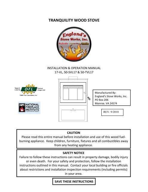
<strong>TRANQUILITY</strong> <strong>WOOD</strong> <strong>STOVE</strong>INSTALLATION & OPERATION MANUAL17‐VL, 50‐SVL17 & 50‐TVL17Manufactured By:England’s Stove Works, Inc.PO Box 206Monroe, VA 24574REV. 9/2010CAUTIONPlease read this entire manual before installation and use of this wood fuelburningappliance. Keep children, furniture, fixtures and all combustibles awayfrom any heating appliance.SAFETY NOTICEFailure to follow these instructions can result in property damage, bodily injuryor even death. For your safety and protection, follow the installationinstructions outlined in this manual. Contact your local building or fire officialsabout restrictions and installation inspection requirements (including permits)in your area.SAVE THESE INSTRUCTIONS
IMPORTANT: IF YOU HAVE A PROBLEM WITH THIS UNIT, DONOT RETURN IT TO THE DEALER. CONTACT TECHNICALSUPPORT @ 1‐800‐245‐6489Mobile <strong>Home</strong> Use:This freestanding wood unit is approved for mobile home ordoublewide installation with the outside combustion air hookup.See the “Installation” section of this manual for detailspertaining to mobile home installations. Mobile homeinstallation must be in accordance with the Manufactured<strong>Home</strong> and Safety Standard (HUD), CFR 3280, Part 24.Retain for your filesModel Number________________________Date of Purchase_______________________Date of Manufacture____________________Serial Number_________________________* This information can be found on the safety tag attached to the rear of the unit.Have this information on hand if you phone the factory or your dealer regarding thisproduct.CAUTION• Keep children away.• Supervise children in the same room as this appliance.• Alert children and adults to the hazards of high temperatures.• Do NOT operate with protective barriers open or removed.• Hot while in operation! Keep clothing, furniture, draperies and othercombustibles away. Contact may cause skin burns!• Installation MUST comply with local, regional, state and national codes andregulations.• Consult local building, fire officials or authorities having jurisdiction aboutrestrictions, installation inspection, and permits.Page | 2
TABLE OF CONTENTSIntroduction• Introduction ................................. 4Specifications• Heating Specifications .................. 5• Dimensions ................................... 5• EPA Compliance ........................... 5Installation• Installation Overview ................... 6• Clearances to Combustibles ......... 7• Venting Introduction .................... 8• Venting Guidelines ....................... 8• Additional Venting Information ... 9• Wall Pass‐Throughs .................... 10• Approved Venting Methodso Through the Wall ........... 11o Through the Ceiling ........ 12o Masonry Chimney .......... 13• Mobile <strong>Home</strong> Installation .......... 14• Outside Air Hook‐Up .................. 14• Floor Protection ......................... 15• R value Calculations ................... 16Operation• Break‐In Fires ............................. 17• Lighting a Fire ............................. 17• Continuous Operation................ 18• Safety Notes ............................... 19Maintenance• Important Notes......................... 20• Inspecting Gaskets ..................... 21• Glass and Gasket Replacement .. 22Troubleshooting Guide• Troubleshooting ......................... 23Optional Accessories• AC‐16 Blower ............................. 24Illustrated Parts Detail• Parts List ..................................... 24• Exploded Parts Diagram ............. 25Warranty• Warranty Details ................... 26‐27• Warranty Reg. Form .............. 28‐29DO NOT CONNECT TO ANY AIR DISTRIBUTION DUCT OR SYSTEM.DO NOT USE CHEMICALS OR FLUIDS TO START THE FIRE.DO NOT BURN GARBAGE OR FLAMMABLE FLUIDS SUCH AS GASOLINE, NAPHTHA ORENGINE OIL.Page | 3
INTRODUCTIONThank you for purchasing this fine product from England’s Stove Works!England’s Stove Works was started, and is still owned by, a family thatbelieves strongly in a “Do It Yourself” spirit; that’s one reason youfound this product at your favorite “Do It Yourself” store.We intentionally design and build our stoves so that any homeownercan maintain their unit with basic tools, and we’re always more thanhappy to show you how to do the job as easily and as inexpensively aspossible. However, while remaining simple, our stoves are designed toperform extremely efficiently, helping deliver more heat from less fuel.Please look at our vast Help section on our website and call ourTechnical Support Department at (800) 245‐6489 if you need any helpwith your unit. We are nearly always able to “walk you through” anyinstallation issues, repairs, problems or other questions that you mayhave.Wishing you years of efficient, quality and “comfy” heating,EVERYONE AT ENGLAND’S <strong>STOVE</strong> WORKSPlease Note: While information obtained from our web site andthrough our Technical Support line is always free of charge, there willbe a service charge incurred with any “on‐site” repairs or maintenancethat we may arrange.Page | 4
SPECIFICATIONSHeating Specifications• Maximum Heat Output ...................................................................... 40,000 BTU/hr• Maximum Burn Time** ................................................................................ 6 hours• Approximate Square Footage Heated*** ..................................... 500 ‐ 1200 sq. ft.• Firebox Capacity ....................................................................................... 45 pounds• Flue Collar ............................................................................................. 6.0 in. roundDimensions31.75 in.30.1875 in.20.375 in. 12.5 in.EPA and Safety Compliance Specifications• EPA Compliance ...........................................................................................Certified• Particulate Emissions ............................................................................ 4.3 grams/hr• Efficiency* ........................................................................................................... 63%• Tested To ............................................................................... UL‐1482, ULC‐S627‐00*‐ This unit was not tested for efficiency; the efficiency shown is a default value normally attained by similar,certified non‐catalytic wood** ‐ Maximum burn time are heavily dependent on the type of wood burned in the stove; as such, these numbersmay vary.*** ‐ The maximum heating capacity of this unit can vary greatly based on climate, construction style, insulationand a myriad of other factors. Use this information in conjunction with a BTU loss calculation for your home todetermine if this unit will be sufficient for your needs.Page | 5
INSTALLATIONInstallation OverviewWhen choosing a location for your new stove, there are a multitude of factors thatshould be taken into account before beginning the installation.1. Traffic Patterns – To help prevent accidents, the stove should be placed in a locationwhere it is out of the way of normal travel through the home.2. Heat Flow – When deciding on a location for the stove, consider the way heat movesthroughout your home. Install the stove where you need the heat; basementinstallations often do not allow sufficient heat to flow to the upper floors and a topfloor installation will not allow any heat to reach the floors below. Always considerthat heat rises and will take the path of least resistance while it is still hot.3. Exhaust Location – The engine which drives a wood stove is the chimney system, soit is important to consider precisely how the chimney system will be integrated intothe stove installation. Ideally, a wood stove chimney will run completely verticalfrom the flue collar of the unit all the way to the termination point above the roofline. Keeping the entire chimney system inside the heated envelope of the homewill ensure a strong, easy to initiate draft in the chimney. Although exterior chimneysystems often function properly, they are more likely to suffer from cold down draftsat start up or provide weak draft to the unit. Also, consider the cross‐sectional areaof the chimney; although existing masonry chimneys can often be used, a largeexternal masonry chimney will result in a unit that is difficult or impossible tooperate properly. In that case, an insulated chimney liner will often be required tosupply the necessary draft.4. Wall Construction – Locating the stove so that the exhaust system can pass betweenstuds will simplify the installation and eliminate the need to reframe any sections ofthe wall or ceiling to accommodate the wall thimble or ceiling box.Page | 6WARNING• Do not store or use gasoline or other flammable vapors and liquids in thevicinity of this or any other appliance.• Do Not Over‐fire – If any external part starts to glow, you are over‐firing.Reduce intake air supply. Over‐firing will void your warranty.• Comply with all minimum clearances to combustibles as specified.Failure to comply may result in a house fire.• Tested and approved for cordwood only. Burning any other fuel willvoid your warranty.
• INSTALLATIONClearances to CombustiblesParallel Wall InstallationABCDCorner InstallationEFSingle Wall ChimneyConnectorUnprotected SurfaceDouble Wall ChimneyConnectorUnprotected SurfaceUnit to SideWallChimneyConnectorto SideWallChimneyConnectorto RearWallUnit toRear WallUnit toCornerChimneyConnectorto CornerA B C D E Fin. (mm.) in. (mm.) in. (mm.) in. (mm.) in. (mm.) in. (mm.)12(304.8)11(279.4)19.5(495.3)17.5(444.5)12(304.8)10(254.0)10(254.0)8(203.2)7(177.8)6(152.4)15(381.0)14(355.6)Page | 7
INSTALLATIONVenting IntroductionThis wood stove operates on anatural draft system, in which the chimneysystem pulls air through the stove. This unitmust be installed in accordance with thefollowing detailed descriptions of ventingtechniques; not installing the stove inaccordance with the details listed here canresult in poor stove performance, propertydamage, bodily injury or death. Avoidmake‐shift compromises when installing theventing system. England’s Stove Works isnot responsible for any damage incurreddue to a poor or unsafe installation.Be certain that all aspects of theventing system are installed to the ventingmanufacturer’s instructions, particularly therequired clearances to combustibles. Also,be certain to use an attic radiation shield toprevent insulation from contacting achimney which passes through an attic.The chimney system is the “engine”which drives a wood stove, so it isimperative for proper unit function that theventing system be installed exactly asdescribed in the following section.If questions arise pertaining to thesafe installation of the stove, our TechnicalSupport line (800‐245‐6489) is available.Contact your local code official to be certainyour installation meets local and nationalfire codes, and if you’re uncertain abouthow to safely install the stove, we stronglyrecommend contacting a local NFI certifiedinstaller to perform the installation.Venting Guidelines• ALWAYS install vent pipe in strictadherence to the instructions andclearances included with yourventing system.• DO NOT connect this wood stove toa chimney flue which also servesanother appliance.• DO NOT install a flue pipe damperor any other restrictive device in theexhaust venting system of this unit.• USE an approved wall thimble whenpassing through a wall and a ceilingsupport/fire stop when passingthrough a ceiling.• INSTALL three sheet metal screws atevery chimney connector joint.• AVOID excessive horizontal runs andelbows, as both will reduce the draftof the venting system and will resultin poor stove performance.• INSPECT your venting system often,to be certain it is clear of creosote,fly‐ash and other restrictions.• CLEAN the venting system asdetailed in the maintenance sectionof this manual.• ADHERE to the 10‐3‐2 rule regardingchimney terminations.• INSTALL single wall chimneyconnector with the male end downto prevent creosote leakage. Followdouble wall chimney connectormanufacturer’s instructionsregarding proper pipe installation.WARNING: Venting system surfaces get HOT, and can cause burns iftouched. Noncombustible shielding or guards may be required.Page | 8
INSTALLATIONAdditional Venting Information• Do not mix and match components from different pipe manufacturers when assemblingyour venting system (i.e. Do NOT use venting pipe from one manufacturer and a thimblefrom another).• We require a minimum chimney height of 15.0 ft. Chimney systems shorter than thismay not create the amount of draft which is required to operate this wood burning unit.• Do not use makeshift compromises when installing the venting system; have existingchimney systems inspected before use and be certain all new chimney systems areinstalled to the manufacturer’s specifications and with only UL listed components.• Prefabricated venting systems used for this stove must be listed to ULC S629 (Canada)and UL 103HT (US).• Never install a draft inducer or any other system which increases the natural draft of thechimney; similarly, do not install a barometric or stovepipe damper with this unit.• Never use single wall or double chimney connector as a chimney system; never passeither type of chimney connector through a combustible wall without carefully followingthe manufacturer’s instructions and those listed in the following page on Wall Pass‐Throughs. NEVER pass chimney connector through an attic, floor, closet or roof.• Only use 24 gauge MSG black single wall chimney connector or UL Listed double wallchimney connector.Single Wall Chimney Connector InstallationThe male end of single wallchimney connector isinstalled facing down so thatany liquid creosote in theflue will run into the unitinstead of onto the outsideof the pipe (the natural draftin the chimney system willprevent smoke leakage atthe joints).Flue Gas DirectionCrimped or male end ofsingle wall chimneyconnector must face down.Fasten each single wallchimney connector jointwith three sheet metalscrews.WARNING• INSTALL VENT AT CLEARANCES SPECIFIED BY THE VENT MANUFACTURER.• HOT! Do not touch! Severe burns or clothing ignition may result.• Glass and other surfaces are hot during operation.Page | 9
INSTALLATIONWall Pass‐ThroughsIn Canada, the installation must conform to CAN/CSA‐B365 when passing through combustible construction.Page | 10
INSTALLATIONApproved Venting Method 1: Through the Wall Factory Built Chimney10 ft.Termination CapStorm CollarRoof Flashing2.0 ft.3.0 ft.The 10‐3‐2 Rule: The chimney systemmust terminate 3.0 ft. above the pointwhere its centerline passes through theroof AND the chimney must terminate2.0 ft. above any part of the dwellingwithin a 10 ft. radius of the chimney.Wall ThimbleChimney Connector(Single or Double Wall)18.0 in.Class A Chimney SystemTee and Tee Support• Prefabricated chimney systems must conform to UL‐103HT (2100 °F) for the U.S. and ULC‐S629 (650°C) forCanada.• This wood burning unit is only listed for installation with 6.0” diameter chimney connector and chimney systems.Installing this unit on prefabricated chimneys larger than 6.0” diameter will result in decreased draft and thepotential for poor unit performance.• Follow all venting system manufacturer’s installation requirements and required clearances.• Use three sheet metal screws at each single wall chimney connector joint (check manufacturer’srecommendations when double wall chimney connector is used).• Drill three holes in the flue collar of the unit and attach the chimney connector to the unit using sheet metalscrews.• Properly attach the prefabricated chimney system to the home in strict accordance with the prefabricatedchimney system manufacturer’s instructions.• Avoid numerous elbows and excessive horizontal runs as both will lead to poor draft and increased creosoteaccumulation. Horizontal runs of chimney connector must never exceed 4.0 ft. and the overall length of thechimney connector must not exceed 8.0 ft.• Special adapters and slip connectors are available to eliminate the need to cut single wall chimney connector.Double wall chimney connector must be used with these slip connectors, as it cannot be trimmed to length.Please Note:Installation diagrams are for reference purposes only and are not drawn to scale, nor meant to be used as plans for each individualinstallation. Please follow all venting system requirements, maintain the required clearances to combustibles, and follow all localcodes.Page | 11
INSTALLATIONApproved Venting Method 2: Through the Ceiling10 ft.Termination CapStorm Collar2.0 ft.3.0 ft.The 10‐3‐2 Rule: The chimney systemmust terminate 3.0 ft. above the pointwhere its centerline passes through theroof AND the chimney must terminate2.0 ft. above any part of the dwellingwithin a 10 ft. radius of the chimney.Roof FlashingClass A Chimney SystemCeiling Support BoxChimney Connector(Single or Double Wall)• Prefabricated chimney systems must conform to UL‐103HT (2100 °F) for the U.S. and ULC‐S629 (650°C) forCanada.• This wood burning unit is only listed for installation with 6.0” diameter chimney connector and chimney systems.Installing this unit on prefabricated chimneys larger than 6.0” diameter will result in decreased draft and thepotential for poor unit performance.• Follow all venting system manufacturer’s installation requirements and required clearances.• Use three sheet metal screws at each single wall chimney connector joint (check manufacturer’srecommendations when double wall chimney connector is used).• Drill three holes in the flue collar of the unit and attach the chimney connector to the unit using sheet metalscrews.• Properly attach the prefabricated chimney system to the home in strict accordance with the prefabricatedchimney system manufacturer’s instructions.• The overall length of the chimney connector must not exceed 8.0 ft. In the case of cathedral ceilings, theprefabricated chimney system should extend to 8.0 ft. from the top of the unit.• Special adapters and slip connectors are available to eliminate the need to cut single wall chimney connector.Double wall chimney connector must be used with these slip connectors, as it cannot be trimmed to length.Page | 12Please Note:Installation diagrams are for reference purposes only and are not drawn to scale, nor meant to be used as plans for each individualinstallation. Please follow all venting system requirements, maintain the required clearances to combustibles, and follow all localcodes.
INSTALLATIONApproved Venting Method 3: Internal or External Masonry Chimney System10 ft.2.0 ft.Chimney liner cross‐sectionalarea (Length x Width) must beno larger than twice the crosssectionalarea of the flue collar(2 x 28.27 in 2 = 56.55 in 2 ). Ifchimney liner is larger than56.55 in 2 , relining with a 5.5”or 6.0” liner is required18.0 in.3.0 ft.The 10‐3‐2 Rule: The chimney systemmust terminate 3.0 ft. above the pointwhere its centerline passes through theroof AND the chimney must terminate2.0 ft. above any part of the dwellingwithin a 10 ft. radius of the chimney.Chimney Connector(Single or Double Wall)Masonry Thimble withproper clearance tocombustiblesAsh Cleanouts musthave an airtight seal toprevent weak draft.• Follow the rules listed above concerning maximum permissible flue liner size; installing this unit on masonrychimneys exceeding 56.55 in 2 in cross‐sectional area will result in decreased draft and the potential for poor unitperformance.• Use three sheet metal screws at each single wall chimney connector joint (check manufacturer’srecommendations when double wall chimney connector is used).• Drill three holes in the flue collar of the unit and attach the chimney connector to the unit using sheet metalscrews.• Avoid numerous elbows and excessive horizontal runs as both will lead to poor draft and increased creosoteaccumulation. Horizontal runs of chimney connector must never exceed 4.0 ft. and the overall length of thechimney connector must not exceed 8.0 ft.• A tight seal at the thimble is crucial for proper unit performance and to create a safe installation. Use the properadapter designed for connecting single or double wall chimney connector to a masonry thimble.• Have existing masonry chimneys inspected for safety and proper clearances to combustibles before putting theminto service; a qualified chimney sweep can perform this inspection.• External masonry chimneys often suffer cold downdrafts and poor draft performance even when they meet thecross‐sectional area rules. In this case, a 6.0” insulated liner may be necessary.Please Note:Installation diagrams are for reference purposes only and are not drawn to scale, nor meant to be used as plans for each individualinstallation. Please follow all venting system requirements, maintain the required clearances to combustibles, and follow all localcodes.Page | 13
INSTALLATIONWARNINGDO NOT INSTALL IN A SLEEPING ROOM.CAUTIONTHE STRUCTURAL INTEGRITY OF THEMANUFACTURED HOME FLOOR, WALL ANDCEILING/ROOF MUST BE MAINTAINED.CautionNEVER draw outside combustion air from:Wall, floor or ceiling cavity orenclosed space such as an attic, garage or crawlspace.Mobile <strong>Home</strong> Installation• The wood stove MUST be secured to the floor of the mobile home using lag bolts and the holesprovided in the bottom of the unit for thisChimney Cap/Spark Arrestorpurpose.• The wood stove must be connected to thechimney system with double wall chimneyconnector which is UL listed for use in mobileand manufactured homes.• Carefully follow all clearances listed in theappropriate section of this manual AND followthe venting manufacturer’s minimumclearance requirements. Similarly, be certainthe venting system used is approved formobile home use.• Installation must be in accordance withManufacturers <strong>Home</strong> & Safety Standard (HUD)CFR 3280, Part 24 as well as any applicable local codes.Outside Combustion Air• The use of outside combustion air is mandatory when installing this wood stove in a mobile ormanufactured home.• The outside air connection pipe protrudes from the bottom center of the stove; a kit is availablefrom England’s Stove Works, Inc. designed for connecting this unit to outside combustion air. [PartNo. AC‐OAK5]• If it is not feasible to use the AC‐OAK5 outside air hookup kit in your stove installation, othermaterials may be used, provided the following rules are followed:oooClass A Chimney SystemRoof Flashing and Storm CollarJoist Shield/FirestopMobile <strong>Home</strong> Approved DoubleWall Chimney ConnectorUse silicone to create a vaporbarrier where the chimney passesthrough to exterior.The pipe used for outside air hookup must be metal, with a minimum thickness of .0209in.(25 gauge mild steel) or greater and an inside diameter of approximately 4.25in.Keep pipe runs short and use a mechanical fastener at each pipe joint.A screen or other protection device must be fitted over the outside air termination point toprevent rain, debris and nuisance animals from entering the piping system. Inspect theoutside combustion air inlet for block and debris monthly.Page | 14
FLOOR PROTECTION• This wood stove requires a non‐combustible floor protector if the stove is to be installed on acombustible floor. If the floor the stove is to be installed on is already non‐combustible (i.e. aconcrete floor in a basement), no floor protection is needed (although a decorative floor protectorcan still be used for aesthetic reasons).• When using any floor protector, consider that this stove is not only heavy but will induce heatingand cooling cycles on the floor protector which can damage tile and loosen mortar and grout jointslocated near the stove.• The floor protector should be UL approved or equivalent and must be noncombustible with an Rvalue of 0.5. Since the majority of the heat from this unit is radiant, the floor protector not onlyserves to keep ashes and sparks from landing on combustible flooring near the unit but alsoprotects the combustible floor from the heat of the unit. A hearth rug is NOT an approvedsubstitute for a proper hearth pad.• For the US: The floor protector must extend at least 16 in. from the front of the fuel opening, 8 in.from the sides of the door opening and 8 in. from the rear of the unit.• For Canada: The floor protector must extend at least 450.0 mm from the front of the fuel opening,200.0 mm from the sides of the door opening and 200.0 mm from the rear of the unit.US: 8.0 in.CANADA: 200.0 mm.US: 8.0 in.CANADA: 200.0 mm.US: 8.0 in.CANADA: 200.0 mm.US: 16.0 in.CANADA: 450.0 mm.• The non‐combustible floor protector must extend 2 in. (50.8 mm.) on either side of any horizontalventing runs and extend directly underneath any vertical venting pipe.• Please see the following page for instructions on calculating R values, to be certain that theplanned floor protection is adequate for this stove.CAUTIONNEVER USE GASOLINE, GASOLINE‐TYPE LANTERN FUEL, KEROSENE, CHARCOAL LIGHTER FLUID,OR SIMILAR LIQUIDS TO START OR “FRESHEN UP” A FIRE IN THIS HEATER. KEEP ALL SUCHLIQUIDS WELL AWAY FROM THE HEATER WHILE IN USE. ADDITIONALLY, NEVER APPLY FIRE‐STARTER TO ANY HOT SURFACE OR EMBERS IN THE <strong>STOVE</strong>.Page | 15
FLOOR PROTECTIONR Value CalculationAn easy means of determining if a proposed alternate floor protector meets requirements isto follow this procedure:1) Convert specification to R‐value:i R‐value is given – no conversion is neededii k‐factor is given with a required thickness (T) in inches: R = 1/k x Tiii C‐factor is given: R = 1/C2) Determine the R‐value of the proposed alternate floor protector:i Use the correct formula given in step 1 (above) to convert values not expressed as“R.”ii For multiple layers, add R‐values of each layer to determine overall R‐value.3) If the overall R‐value of the system is greater than the R‐value of the specified floorprotector, the alternate is acceptable.EXAMPLE:The specified floor protector should be ¾” thick material with a k‐factor of 0.84. Theproposed alternate is 4” brick with a C‐factor of 1.25 over 1/8” mineral board with a k‐factor of 0.29.Step (a):Step (b):Use formula above to convert specification to R‐value.R = 1/k x T = 1/0.84 x .75 = 0.893Calculate R of proposed system.4” brick of C = 1.25, therefore R brick = 1/C =1/1.25 = 0.801/8” mineral board of k = 0.29, therefore Rmin.bd. = 1/0.29 x 0.125 = 0.431Total R = R brick + R mineral board = 0.8 + 0.431 = 1.231Step (c): Compare proposed system of R of 1.231 to specified R of 0.893. Since proposedsystem R is greater than required, the system is acceptable.Definitions:Thermal conductance = C = _____Btu____ = ____W____(hr)(ft 2 )(deg F) (m 2 )(deg K)Thermal conductivity = k = __(Btu)(inch)__ = ___W____ = ____Btu____(hr)(ft 2 )(deg F) (m)(deg K) (hr)(ft)(deg F)Thermal resistance = R = (ft 2 )(hr)(deg F) = (m 2 )(deg K)BtuWPage | 16
OPERATIONBreak‐In Fires• This wood burning unit is constructed of heavy gauge steel and cast iron and is built to last along time. However, in order to ensure no excessive thermal stresses are induced on the metalduring the first fire, three break‐in fires should be burned, each one slightly hotter than the last.These break‐in fires will not only help the stove body acclimate to the high temperatures of thefire, but will also slowly cure the high temperature stove paint, which will ensure the highquality finish lasts for years.• This stove has a single air control rod which regulates the wood burn rate; when the primary aircontrol slide is pulled all the way out of the unit, the stove will burn more slowly and put outheat over a longer time period. Conversely, when the air control slide is pushed all the way in,the unit will burn more quickly and put out a larger amount of heat over a relatively shortertime period. Do not attempt to modify the range of air control adjustment for any reason.• The first break‐in fire should be just a large kindling fire, getting the stove to about 300°F asmeasured by a magnetic thermometer on the right or left side of the stove, above the door.Once this temperature has been reached, allow the fire to die out with the air control open. Thesecond and third break‐in fires should be a bit larger, with some small dry splits added to thekindling load. The temperature goal during these fires is about 350°F – 450°F; don’t let the fireget hotter than that.Continuous Operation• After the break‐in fires are complete, this unit is ready for continuous operation. When burningthe stove continuously, do not allow ash and coals to accumulate higher than 1.0” below thedoor opening. Excessive coaling is often a result of burning wood at too high a burn rate, andthe coal bed should be allowed to burn down before reloading the stove with fresh wood.• Combustion air is delivered to the stove at two locations: The majority of the primarycombustion air enters the firebox via the air‐wash system which keeps the glass clean and feedsthe primary combustion flames on the top surfaces of the wood; some primary combustion air isbled off into the coal bed via bleed holes in the bottom rail of the air‐wash system. Every effortmust be taken to maintain the area in front of these holes free of ash.• When loading the stove for a long term burn, it is most useful to rake a “v” in the center of thecoal bed, to allow the primary air bleed holes to push air all the way to the rear of the unit.• After loading the stove with a full firebox of fresh wood, it is important to operate the unit withthe air control in the full open position to properly char the wood load and drive off the initialmoisture in the fresh wood. Once the wood has been properly charred and is completelyignited, the air control can then be set to the desired heat output level.In the event of a creosote or soot fire (chimney fire), close the air control on thestove, contact the local fire department and get out! Do not throw water on the fire!Contact your local fire authority for more information on how to handle a chimneyfire and develop a safe evacuation plan for you and your family in the event of achimney fire.Page | 17
OPERATION• England’s Stove Works, Inc. always recommends the use of a magnetic stove thermometer, sothat the temperature of the unit can be monitored. When using a magnetic stove thermometer,locate the thermometer above the door on either the left or right side of the stove and use thefollowing temperatures as rough guidelines to determine the burn rate and heat output level ofthe stove:o Normal wood stove operation should occur between 350°F (177°C) and 550°F (288°C),with 350°F (177°C) to 450°F (232°C) being a low to medium heat output level and 450°F(232°C) to 550°F (288°C) being a medium to high heat output level. Operating the stoveat 600°F (316°C) would be considered the maximum continuous operating temperaturepermissible and unit damage may result from operating at that high of a burn rate forextended time periods. Allowing the unit to reach 650°F (343°C) or higher is defined asover‐firing and will result in unit damage.• The optional room air convection blower was designed to extract the maximum amount of heatfrom the stove, for the highest possible heat transfer into the room. Since the blower is soefficient at removing heat from the unit, it is very important to only operate the room air blowerafter a fresh wood load has been allowed to burn for at least thirty (30) minutes. Allowing afresh load of wood to burn without the blower on ensures that the entire unit reaches properoperation temperatures and that the secondary combustion system is functioning properly.Additionally, follow the guidelines below for acceptable blower speeds.• When using the optional room air convection blower (Part No. AC‐16), the blower should beoperated as follows depending on heat output level:Burn rate High Medium High Medium Medium Low LowBlower Speed High Low Low Low OffCreosote – Formation and Need for RemovalWhen wood is burned slowly, it produces tar and other organic vapors, whichcombine with expelled moisture to form creosote. The creosote vaporscondense in the relatively cool chimney flue of a slow‐burning fire. As a result,creosote residue accumulates on the flue lining. When ignited, this creosotemakes an extremely hot fire. The chimney and chimney connector should beinspected at least once every two months during the heating season todetermine if a creosote buildup has occurred. If creosote has accumulated, itshould be removed to reduce the risk of chimney fire.DO NOT USE GRATE OR ELEVATE FIRE – BUILD <strong>WOOD</strong> FIRE DIRECTLY ON HEARTHDO NOT OPERATE WITH THE MAIN DOOR OPEN – OPERATING THE <strong>STOVE</strong> WITH THE MAINDOOR OPEN WILL CREATE AN OVER‐FIREPage | 18
Page | 20MAINTENANCEDaily Maintenance• Inspect the firebox for ash accumulation; remove excess ash and follow instructionsbelow regarding disposal. Ash should not be allowed to accumulate in the stove to thepoint that it covers the coal bed air inlets.Monthly Maintenance• Check the blower for dust accumulation (if installed); check the door handle for properoperation and to be certain an airtight seal is still being made by the door.• Inspect the chimney system and chimney connector and sweep if necessary. Althoughcleaning may be required less than monthly, ALWAYS inspect the venting systemmonthly to decrease the chance of a chimney fire.• Visually inspect the vermiculite insulating boards in the firebox for cracks and/orbreakage. Slight surface cracks will not affect the performance of the boards, butcracked or crumbling boards should be replaced immediately.• Visually inspect the secondary combustion tubes for cracks, warping and corrosion.Although these tubes are constructed from stainless steel, they operate at very hightemperatures and can eventually wear out from normal use.Yearly Maintenance• Check all gaskets (window and door) for wear and to be certain they still maintain anairtight seal. See the following page for instructions.• Thoroughly clean the chimney system and the chimney connector system. Since thechimney connector is generally exposed to high exhaust temperatures, inspect itcarefully for leaks and weak spots; replace any questionable pieces. [In the case ofstraight through the roof chimney system, be certain to remove the vermiculite bafflebefore pushing the chimney sweeping brush down into the firebox. Forcefully hittingthe top of the baffle with a cleaning brush or rod can damage or destroy the baffle.]• Remove all ash from the stove, including the ash which accumulates on the top of thefirebox baffles. Leave the air control open during the non‐heating months to allowsome air to flow through the stove to help prevent corrosion. A small open container ofcat litter in the stove can help prevent corrosion during the humid summer months; becertain to remove it before building a fire in the fall.IMPROPER GASKET MAINTENANCE, INCLUDING FAILURE TO REPLACE GASKETS, CANCAUSE AIR LEAKS RESULTING IN AN UNCONTROLLABLE UNIT.Disposal of Ashes – Ashes should be placed in a metal container with a tight fitting lid. Theclosed container of ashes should be placed on a noncombustible floor or on the ground, wellaway from all combustible materials, pending final disposal. If the ashes are disposed of byburial in soil or otherwise locally dispersed, they should be retained in the closed containeruntil all cinders have been thoroughly cooled.
MAINTENANCEInspecting GasketsAn airtight seal at the door opening is crucial to proper stove performance. Any air leakageat this area can cause an over‐fire situation and is therefore a serious safety threat. Because ofthis, gaskets should always be maintained in good condition. Gasket tightness can be checkedusing the “dollar‐bill” method:• Place a dollar bill between the gasket and the stove body (at the location where thegasket meets the stove).• Tighten the latching mechanism down and attempt to pull the dollar bill out. If thedollar bill slides in and out easily, the gasket needs to be replaced. This test should berepeated around the entire gasket perimeter, as gaskets will sometimes seal tightly onone side, but will be worn and seal poorly on another side.• Perform this test around the entire perimeter of the door, and visually inspect thewindow gasket for any leaks. Leaks in the window gasket can generally be located byfollowing the prevailing soot trails left on the window after burning the unit.• If any area fails the test, the entire gasket should be replaced. The part numberappropriate to the gasket being replaced can be found in the “Illustrated Parts” sectionof this manual.• Gaskets should only be replaced with equivalent fiberglass gaskets purchased fromEngland’s Stove Works ® specifically for this unit.Gaskets1. Door ‐ This unit comes with a 5 / 8 ” rope gasket around the door that should be replacedat least every two years. To replace the door gasket (Part # AC‐DGKNC), the old gasketmust first be removed entirely — prior to adding the new adhesive, you may have toscrape the old cement from the door channel. Once the cement and gasket have beenadded, the door should be closed and latched for twenty‐four hours to allow the cementto harden.2. Window ‐ If you are replacing the window gasket (Part # AC‐GGK), the new gasket willalready have adhesive on one side. First, remove the old gasket. Next, remove thepaper on the adhesive side and place the gasket around the outside edge of the glass,centered over the edge. Fold the gasket edges over on the glass, forming a “U” shape.FinishThis new unit has been painted with High‐Temperature Paint that should retain itsoriginal look for years. If the unit should get wet and rust spots appear, the spots can be sandedwith fine steel wool and repainted. It is crucial that only High‐Temperature Spray Paint is used(Part # AC‐MBSP), as others may not adhere to the surface or withstand the high temperatures.Similarly, some brands of paint will not adhere to different brands of paint, so we highlyrecommend using our proprietary High‐Temperature Spray Paint.Page | 21
REPLACING COMPONENTSGlassThis unit has a ceramic glass panel (Part No. AC‐G40) in the viewing door; self adhesivewindow gasket is included with replacement windows purchased directly from England’s StoveWorks. Never replace ceramic glass with tempered or any other type of glass and never operatethis unit with cracked or broken glass.• Glass Size: 14.5 in. (368.3 mm) x 10.75 in. (273.05 mm)• Glass Type: 5mm Ceramic Glass (Keralite Pyroceram)• Glass Manufacturer: EurokeraGlass Precautions1. Never replace ceramic glass with tempered or any other type of glass.2. Never operate this unit with cracked or broken glass.3. Do not slam the door or strike the glass with any objects.4. Do not build the fire directly against the glass.Glass Cleaning1. Be certain the stove and the glass are completely cool.2. The build‐up on the glass will generally be light and water is normally sufficient toremove the deposits. If stubborn soot persists, use a cleaner made specifically for thispurpose. Do not scrape the glass or use abrasive cleaners.3. Rinse the glass with clean water and dry the glass before resuming normal operation.Glass Replacement1. Remove the door from the stove and rest it face down on a firm work surface.2. Using a 5/16” wrench, remove the four window bracket retaining screws.3. Remove the two window brackets from the door. Take extra care to avoid shards ofglass if the glass window has been broken.Retaining Screws4. Lift the old glass panel out of the door andGlass Gasketdiscard.5. The new glass panel must be wrapped withGlass Panela self‐adhesive fiberglass tape gasket (AC‐GGK). This gasket serves to cushion theglass from the cast iron door.6. Reinstall the window retaining bracketsusing the four screws previously removed.Window BracketDo not over‐tighten the screws.Page | 22
TROUBLESHOOTINGIssue Cause Solution(s)Stove smokes into room 1. Weak Draft 1.1 Be certain chimney is sufficiently tall tomeet the 10‐3‐2 rule.2. Negative Pressure inthe <strong>Home</strong>1.2 Add additional height to the chimney.2.1 Add an outside combustion air hookup tothe unit.Fire is hard to start 3. Weak Draft 3.1 Be certain chimney is sufficiently tall tomeet 10‐3‐2 rule.3.2 Add additional height to the chimneysystem.4. Cold Chimney 4.1 Heat the flue first by burning crumblednewspaper in the stove.5. Downdraft inChimney4.2 Install an insulated chase around externalchimneys.5.1 Be certain chimney is sufficiently tall tomeet 10‐3‐2 rule.5.2 Try heating the flue with a hair‐dryer tocorrect the draft.Glass is dirty 6. Wet or Green Wood 6.1 Only burn wood that is seasoned for atleast one year and that is dry and free of iceand snow.Coals build up in firebox7. Operating Stove atLow Burn Rate8. Wood Loaded TooClose to Glass9. Operating Stove atHigh Burn Rates7.1 Operate the stove at higher burn rates toallow the air‐wash system to keep the glassclean.8.1 Never load wood so that it is touching theceramic glass viewing window.9.1 Reduce combustion air control and allowcoals to burn down before reloading.Fire burns out of control 10. Excessive Draft 10.1 Reduce chimney height.Excessive smoke from stack11. Air Leakage 11.1 Inspect window and door gaskets andreplace if necessary.12. Burning ExcessivelyDry Wood13. Operating Stove atLow Burn Rate14. Wet or GreenWood12.1 Only burn seasoned cord wood. Do notburn kiln dried wood or pallet wood.13.1 Operate the stove at a higher burn ratewhich will create secondary combustion.14.1 Only burn wood that is seasoned for atleast one year and that is dry and free of iceand snow.15. Not Charring FreshWood Load15.1 Char the fresh wood load until it iscompletely ignited and active secondarycombustion is present in the firebox.Page | 23
REPLACEMENT PARTS LISTDiagramNo.Description Part No. Per Unit1 Air Control Slider AC‐17ACS 12 Outside Air Adapter AC‐17OAA 13 Right Vermiculite Panel AC‐17RBR 14 Left Vermiculite Panel AC‐17RBL 15 Rear Vermiculite Panel AC‐17RBB 26 9" x 4" x 1.25" Firebrick AC‐SB 47 Top Vermiculite Baffle AC‐17RBT 18 Door Gasket [5/8" dia HD] AC‐DGKNC 19 Window Gasket AC‐GGK 110 Ceramic Glass Panel AC‐G40 111 Window Retaining Brackets AC‐GS16 212 Cast Iron Door CA‐16 113 Secondary Tube (Front) AC‐17BTF 114 Upper Refractory Baffle AC‐17URBVL 115 Secondary Tube (Rear) AC‐17BTR 1Not Shown Large Spring Handle AC‐SH (Brass) 1AC‐SHN (Nickel)Not Shown Air Control Spring Handle AC‐SH4 (Brass) 1AC‐SH4N (Nickel)OPTIONAL ACCESSORIESAC‐16 Convection BlowerThe Tranquility wood stove was also designed for use with a convection blower foradditional heat circulation. The stove is constructed with rear and top convection channelswhich allow the room air blower to pick up heat from the hottest regions of the stove andtransfer it into the home. The mounting screws for the blower are installed into the rearconvection channel at the factory; mounting the blower only requires a 5/16” open end orsocket wrench to remove these screws and install the blower. When routing the power cord,take care to keep away from hot areas of the unit and remember that this blower is for use onlywith the stove. Please see the diagram below for clarification on the room air blowerinstallation.(4) 5/16” head, self tappingscrews (pre‐installed in unit).WarningDisconnect theelectrical power fromthe fan beforeinstallation.The optional heat circulation blower on this stove requires periodic lubrication; this lubricationshould be performed no less than every three months of normal operation. To properly lubricate theblower, use an eye dropper or similar dispensing device to drip 5-7 droplets of SAE 20 oil into thePageoil port| 24on the side of the blower motor.
ILLUSTRATED PARTS DIAGRAM15714Welded SteelStove Body134525Cast Iron DoorAssembly3619111081211Window Retaining ScrewsPage | 25
Page | 26You may write your unit’s Manufacture Date and SerialNumber in the blank spaces on this sample tag, for futurereference. This sample tag also shows the safety info.such as UL testing standard, etc. for your local officials,or anyone else who may need reference information.
LIMITED FIVE (5) YEAR WARRANTYFrom the date of purchase to the original ownerThe manufacturer extends the following warranties:Five Year Period:1. Carbon steel and welded seams in the firebox are covered for five (5) yearsagainst splitting.2. The cast iron door and hinges are covered for five (5) years againstcracking.One Year Period:1. Electrical components, accessory items, glass and the painted surface of thestove are covered for one (1) year from the date of purchase.Conditions and Exclusions1. Damage resulting from over‐firing will void your warranty.2. This warranty does not apply if damage occurs because of an accident,improper handling, improper installation, improper operation, abuse orunauthorized repair made or attempted to be made.3. The manufacturer is not liable for indirect, incidental, or consequentialdamages in connection with the product including any cost or expense,providing substitute equipment or service during periods of malfunction ornon‐use.*4. All liability for any consequential damage for breach of any written orimplied warranty is disclaimed and excluded.5. This warranty does not cover internal wear parts of the combustion system,including the vermiculite firebox lining and gaskets.• Some states do not allow the exclusion of limitations of incidental or consequential damages, so the above may not apply to you.Page | 27
ProcedurePurchaser must give notice of claim of defect within the warranty periodand pay transportation to and from a service center designated by themanufacturer. The dealer from which the unit was purchased or the factory,at our option, will perform the warranty service.Other RightsThis warranty gives you specific legal rights; you may also have other rights,which may vary from state to state.Please Note: This warranty is null and void if the attached warranty registration ANDa copy of the sales receipt is not returned within thirty (30) days from the date ofpurchase.Warranty is not transferable.Page | 28
WARRANTY REGISTRATION for England’s Stove Works®Purchaser InformationI. Purchased By (Name) _________________________________________II. Address ____________________________________________________III. City_______________________State________Zip Code ____________IV. Telephone Number ___________________________________________V. Email Address _______________________________________________Dealer InformationVI. Purchased From _____________________________________________VII. Address ___________________________________________________VIII. City_______________________ State________ Zip Code __________Unit Information*Refer to the sticker on the back of the manual or box to complete this section.IX. Model Number_____________________ Purchase Date _____________X. Purchase Price_____________________XI. Serial Number_____________________ Mfg. Date _________________Purchase QuestionsHow did you first hear about our product? (Please check one)Word of Mouth ____ Burn Trailer Demonstration____ Internet____Other: ________________________________________________________Where did you receive information about our product?Via Telephone____ Dealer (Name of dealer) ___________ Internet____Other: ________________________________________________________Page | 29
Important NoticeThis registration information MUST be on file for this warranty to be valid. Pleasemail this information within thirty (30) days from the original date of purchase.Use any of these three easy ways to send your warranty information in!Mailing AddressEngland’s Stove Works, Inc.Technical Support DepartmentP.O. Box 206Monroe, Virginia 24574Fax Number(434) 929-4810 – Twenty-four hours a day.Online RegistrationVisit our warranty registration website at:http://www.englanderstoves.com/warranty/warranty.htmlPage | 30