

rectimat 2 varlogic user manual - Schneider Electric
rectimat 2 varlogic user manual - Schneider Electric
rectimat 2 varlogic user manual - Schneider Electric

Create successful ePaper yourself
Turn your PDF publications into a flip-book with our unique Google optimized e-Paper software.
Merlin Gerin<br />
Varlogic RT6 power factor controller<br />
1. INTRODUCTION<br />
1.1 About User Manual<br />
This User Manual is designed to help you for quick installation of RT6. Before installation<br />
and operation please, read this section very carefully.<br />
1.2 Precautions for Safe Use and Installation<br />
1) Maintenance, installation and operation of RT6 must be performed only by the qualified<br />
electricians.<br />
2) Disconnect power before working on the equipment.<br />
3) Do not operate RT6 undervoltage.<br />
4) Do not open the RT6’s housing.There are no <strong>user</strong> servicable parts inside it.<br />
5) RT6 is connected to the network by means of a current transformer. Do not disconnect<br />
the current transformer terminals, if you disconnect them, be sure to short circuit or<br />
connect them to another parallel load having sufficiently low impedance.In case of<br />
failure dangerously high voltage at the secondary side of current transformer may cause<br />
an electric shock.<br />
6) Do not use this product for any other purpose than its original task.<br />
7) When the device is connected to the network, do not remove the front panel.<br />
8) Do not clean the device with solvent or the like. Only clean with a dried cloth.<br />
9) Verify correct terminal connections when wiring.<br />
10) <strong>Electric</strong>al equipment should be serviced only by your competent seller.<br />
11) Only for rack panel mounting.<br />
2. GENERAL<br />
Power Factor Controllers are used for measurement and control of power factor control units<br />
for central reactive power compensation.The Power Factor measured by RT6 is compared<br />
with the set point values in order to provide necessary compensation, Power Factor Controller<br />
switches capacitor steps ON and OFF automatically.RT6 is microcontroller relay, designed<br />
for flush mounting with rear plug-in connectors.In addition it displays the system’s Cosj,in<br />
Automatic Operating Mode, RT6 displays the RMS value of Voltage (V), Current (I), Active<br />
Power (W), Reactive Power (kvar) and Apparent Power (VA) of measuring phase.<br />
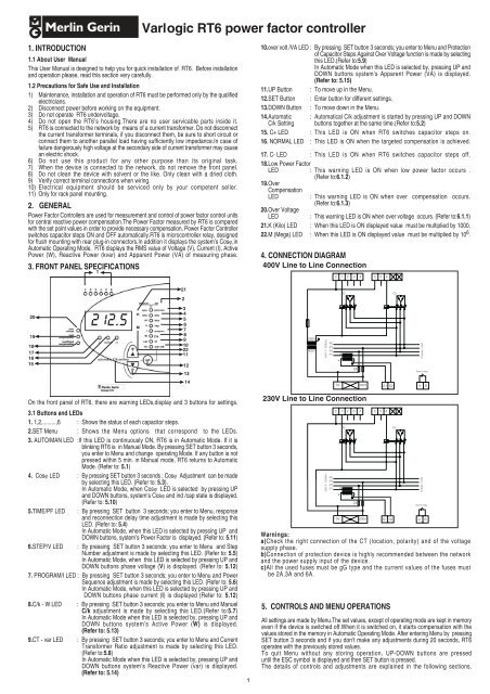
3. FRONT PANEL SPECIFICATIONS<br />
10.over volt /VA LED : By pressing SET button 3 seconds; you enter to Menu and Protection<br />
of Capacitor Steps Against Over Voltage function is made by selecting<br />
this LED.(Refer to:5.9)<br />
In Automatic Mode when this LED is selected by, pressing UP and<br />
DOWN buttons system’s Apparent Power (VA) is displayed.<br />
(Refer to: 5.15)<br />
11.UP Button : To move up in the Menu.<br />
12.SET Button : Enter button for different settings.<br />
13.DOWN Button : To move down in the Menu.<br />
14.Automatic : Automatical C/k adjustment is started by pressing UP and DOWN<br />
C/k Setting buttons together at the same time.(Refer to:5.2)<br />
15. C+ LED : This LED is ON when RT6 switches capacitor steps on.<br />
16. NORMAL LED : This LED is ON when the targeted compensation is achieved.<br />
17. C- LED : This LED is ON when RT6 switches capacitor steps off.<br />
18.Low Power Factor<br />
LED : This warning LED is ON when low power factor occurs .<br />
(Refer to:6.1.2)<br />
19.Over<br />
Compensation<br />
LED<br />
: This warning LED is ON when over compensation occurs.<br />
(Refer to:6.1.3)<br />
20.Over Voltage<br />
LED<br />
: This warning LED is ON when over voltage occurs. (Refer to:6.1.1)<br />
21.K (Kilo) LED : When this LED is ON displayed value must be multiplied by 1000.<br />
22.M (Mega) LED : When this LED is ON displayed value must be multiplied by 10 6 .<br />
4. CONNECTION DIAGRAM<br />
400V Line to Line Connection<br />
C 1 2 3 4 C 5 6<br />
C1<br />
C6<br />
230V<br />
400V<br />
400V 3~ 50/60Hz<br />
PE<br />
P3<br />
P2<br />
P1<br />
K<br />
k<br />
L<br />
I<br />
Charge / Load<br />
2A<br />
Alarm relay<br />
0V<br />
400V<br />
S1 S2 A B<br />
On the front panel of RT6, there are warning LEDs,display and 3 buttons for settings.<br />
3.1 Buttons and LEDs<br />
1. 1,2,.........,6 : Shows the status of each capacitor steps.<br />
2.SET Menu : Shows the Menu options that correspond to the LEDs.<br />
3. AUTO/MAN LED :If this LED is continuously ON, RT6 is in Automatic Mode. If it is<br />
blinking RT6 is in Manual Mode. By pressing SET button 3 seconds,<br />
you enter to Menu and change operating Mode. If any button is not<br />
pressed within 5 min. in Manual mode, RT6 returns to Automatic<br />
Mode. (Refer to: 5.1)<br />
4. Cosj LED : By pressing SET button 3 seconds ; Cosj Adjustment can be made<br />
by selecting this LED. (Refer to: 5.3).<br />
In Automatic Mode, when Cosj LED is selected by pressing UP<br />
and DOWN buttons, system’s Cosj and ind /cap state is displayed.<br />
(Refer to: 5.10)<br />
5.TIME/PF LED : By pressing SET button 3 seconds; you enter to Menu, response<br />
and reconnection delay time adjustment is made by selecting this<br />
LED. (Refer to: 5.4)<br />
In Automatic Mode, when this LED is selected by pressing UP and<br />
DOWN buttons, system’s Power Factor is displayed. (Refer to: 5.11)<br />
6.STEP/V LED : By pressing SET button 3 seconds; you enter to Menu and Step<br />
Number adjustment is made by selecting this LED. (Refer to: 5.5)<br />
In Automatic Mode, when this LED is selected by pressing UP and<br />
DOWN buttons phase voltage (V) is displayed. (Refer to: 5.12)<br />
7. PROGRAM/I LED : By pressing SET button 3 seconds; you enter to Menu and Power<br />
Sequence adjustment is made by selecting this LED. (Refer to: 5.6)<br />
In Automatic Mode, when this LED is selected by pressing UP and<br />
DOWN buttons phase current (I) is displayed (Refer to: 5.12)<br />
8.C/k - W LED : By pressing SET button 3 seconds; you enter to Menu and Manuel<br />
C/k adjustment is made by selecting this LED.(Refer to:5.7)<br />
In Automatic Mode when this LED is selected by, pressing UP and<br />
DOWN buttons system’s Active Power (W) is displayed.<br />
(Refer to: 5.13)<br />
9.CT - var LED : By pressing SET button 3 seconds; you enter to Menu and Current<br />
Transformer Ratio adjustment is made by selecting this LED.<br />
(Refer to:5.8)<br />
In Automatic Mode when this LED is selected by, pressing UP and<br />
DOWN buttons system’s Reactive Power (var) is displayed.<br />
(Refer to: 5.14)<br />
1<br />
230V Line to Line Connection<br />
230V 3~ 50/60Hz<br />
Warnings:<br />
a)Check the right connection of the CT (location, polarity) and of the voltage<br />
supply phase.<br />
b)Connection of protection device is highly recommended between the network<br />
and the power supply input of the device.<br />
c)All the used fuses must be gG type and the current values of the fuses must<br />
be 2A,3A and 6A.<br />
5. CONTROLS AND MENU OPERATIONS<br />
PE<br />
P3<br />
P2<br />
P1<br />
C 1 2 3 4 C 5 6<br />
K<br />
k<br />
C1<br />
L<br />
I<br />
2A<br />
0V 230V<br />
S1 S2<br />
A B<br />
All settings are made by Menu.The set values, except of operating mode are kept in memory<br />
even if the device is switched off.When it is switched on, it starts compensation with the<br />
values stored in the memory in Automatic Operating Mode. After entering Menu by pressing<br />
SET button 3 seconds and if you don’t make any adjustments during 20 seconds, RT6<br />
operates with the previously stored values.<br />
To quit Menu without any storing operation, UP-DOWN buttons are pressed<br />
until the ESC symbol is displayed and then SET button is pressed.<br />
The details of controls and adjustments are explained in the following sections.<br />
C6<br />
Charge / Load<br />
Alarm relay
5.1 Selection of Operating Mode (Automatic / Manual Mode )<br />
Two Operating Modes are valid for switching on/off the capacitor steps.<br />
1) Automatic Operating Mode: The capacitor steps are controlled by RT6, automatically.<br />
2) Manual Operating Mode: the capacitor steps are switched on/off, <strong>manual</strong>ly.<br />
RT6 returns to Automatic mode if any button is not pressed within 5 minutes.<br />
Mode selection is done as followed.<br />
SET<br />
By pressing SET button 3 seconds SET Menu is started.<br />
5.5 Step Number Selection<br />
UP<br />
SET<br />
DOWN<br />
By pressing SET button 3 seconds SET<br />
Menu is started.<br />
Display<br />
STEP LED is selected by means of<br />
UP-DOWN buttons. StEP symbol is displayed.<br />
UP<br />
UP<br />
SET<br />
DOWN<br />
DOWN<br />
Display<br />
AUTO/MAN LED is selected by using<br />
UP-DOWN buttons. symbol is displayed.<br />
AUTO/MAN setting is selected by pressing SET<br />
button.If the device is in Manuel Mode<br />
symbol is displayed.If the device is in Automatic<br />
Mode symbol is displayed.<br />
Automatic Mode ( ) or Manual Mode ( ) is<br />
selected by using UP-DOWN buttons.<br />
UP<br />
SET<br />
SET<br />
DOWN<br />
STEP number adjustment is selected by pressing<br />
SET button.Previously selected value is shown on<br />
the display<br />
A preferred step number is selected by<br />
means of UP-DOWN buttons.<br />
When targeted value is displayed, it is stored by<br />
pressing SET button and RT6 returns to its<br />
normal operating mode.<br />
5.6 Switching Program Selection<br />
SET<br />
When targeted operating mode is displayed it is selected by pressing SET button. If<br />
Manual Mode is selected AUTO/MAN LED starts blinking and blinks during this mode.If<br />
Automatic Mode is selected AUTO/MAN LED is continuouslly ON during this mode.<br />
5.1.1 Switching of the Capacitor Steps Manually<br />
When RT6 is in Manual Mode, capacitor steps are connected by pressing UP button.<br />
Each time UP button is pressed C+ light is ON ,and one step is connected after set response<br />
delay time.<br />
NORMAL light will be ON after the connection of the step.This operation must be repeated<br />
to connect more steps.<br />
Capacitor steps are disconnected by pressing DOWN button. Each time DOWN button is<br />
pressed C- light is ON ,and one step is disconnected after set response delay time. NORMAL<br />
light will be ON after the disconnection of the step.This operation must be repeated to<br />
disconnect more steps.<br />
5.2 Automatic C/k Adjustment<br />
UP<br />
UP<br />
SET<br />
SET<br />
SET<br />
DOWN<br />
DOWN<br />
By pressing SET button 3 seconds SET Menu is started.<br />
Display<br />
PROGRAM LED is selected by means<br />
of UP-DOWN buttons. symbol is<br />
displayed.<br />
Switching Program is selected by<br />
pressing SETbutton.Previously<br />
selected value is shown on the display<br />
A value between PS1-PS9 is selected by<br />
using UP-DOWN buttons.<br />
When targeted program is displayed, it is stored by pressing SET button<br />
and RT6 returns to its normal operating mode.<br />
UP<br />
5.3 Cosj Adjustment<br />
By pressing SET button 3 seconds SET<br />
SET Menu is started.<br />
Display<br />
UP<br />
DOWN<br />
DOWN<br />
C/k adjustment is started by pressing UP-DOWN<br />
buttons together.<br />
Cosj LED is selected by using UP<br />
and DOWN buttons. COS symbol is<br />
displayed<br />
5.7 Selection of C/k Value by the User<br />
UP<br />
SET<br />
SET<br />
DOWN<br />
By pressing SET button 3 seconds SET Menu is started.<br />
Display<br />
C/ k LED is selected by means of<br />
UP-DOWN buttons. symbol is<br />
displayed.<br />
Manual C/ k adjustment is selected by pressing<br />
SET button. Previously <strong>manual</strong>ly selected or<br />
automatically calculated C/ k value is shown<br />
on the display<br />
UP<br />
SET<br />
DOWN<br />
Cosj adjustment is selected by pressing<br />
SET button. Previously adjusted value<br />
is shown at the display<br />
A value between 0.85-1.00 is adjusted<br />
by using UP-DOWN buttons.<br />
M<br />
UP<br />
SET<br />
DOWN<br />
A value between 0.02-1 is selected by<br />
using UP-DOWN buttons.<br />
When targeted value is displayed, it is stored by<br />
pressing SET button and RT6 returns to its<br />
normal operating mode.<br />
UP<br />
UP<br />
SET<br />
SET<br />
SET<br />
SET<br />
DOWN<br />
DOWN<br />
When targeted value is displayed, it is stored<br />
by pressing SET button and RT6 returns to its<br />
normal operating mode.<br />
5.4 Response and Reconnection Delay Time Adjustment<br />
By pressing SET button 3 seconds SET Menu is started.<br />
Display<br />
TIME LED is selected by means of<br />
UP-DOWN buttons.<br />
While TIME LED is ON, t 0n symbol is<br />
displayed by means of UP-DOWN buttons<br />
and response delay time adjustment is<br />
selected by pressing SET button.<br />
While TIME LED is ON, t rC symbol is<br />
displayed by means of UP-DOWN buttons<br />
and reconnection delay time adjustment is<br />
selected by pressing SET button.<br />
A response and reconnection delay time value<br />
is adjusted by using UP-DOWN buttons.<br />
When targeted value is displayed it is stored by pressing SET button and<br />
RT6 returns to its normal operating mode.<br />
Note: Factory set values are 10 sec. for response delay and 50 sec. for reconnection delay<br />
5.8 Selection of Current Transformer Primary Value<br />
UP<br />
UP<br />
SET<br />
SET<br />
SET<br />
DOWN<br />
DOWN<br />
By pressing SET button 3 seconds SET<br />
Menu is started.<br />
Display<br />
CT LED is selected by means of UP-<br />
DOWN buttons. Ct symbol is displayed.<br />
Current Transformer Primary Value is selected<br />
by pressing SET button. Previously selected<br />
CT value is shown on the display.<br />
A value between 5--1 0 0 00 is adjusted by<br />
using UP-DOWN buttons.<br />
When targeted value is displayed, it is stored by<br />
pressing SET button and RT6 returns to its normal<br />
operating mode.<br />
5.9 Protection of Capacitor Steps Against Over Voltage<br />
This function can be programmed between 240-275V (for 185 ... 265V AC) or<br />
410-480V (for 320 ... 460V AC) or disabled O OF (Over Voltage Protection Off).<br />
If "Over Voltage" occurs, all the capacitor steps switch off, OVER VOLTAGE LED<br />
turns on and alarm relay activates with 1 min. delay.And if RT6 is on Manuel Mode, it<br />
switches to Automatic Mode.If 0 0F (Over Voltage Protection Off) is selected; Over Voltage<br />
Protection is disabled. Setting can be made as followed:<br />
N o 03653496EN-AA<br />
2
SET<br />
Push SET button 3 seconds and enter SET<br />
Menu.<br />
Display<br />
P<br />
1.25xQ C1<br />
UP<br />
UP<br />
SET<br />
DOWN<br />
DOWN<br />
Scroll to "OVER V." by UP/DOWN<br />
buttons.OV is displayed.<br />
Push SET button for Over Voltage<br />
Protection setting. Either O OF or<br />
preset over voltage value is<br />
displayed.<br />
Select either O OF to cancel Over<br />
Voltage Protection Function or select<br />
a voltage value by UP/DOWN buttons.<br />
-Q<br />
j:adjusted value<br />
6.3 Adjustable Response And Reconnection Delay Time<br />
j<br />
Response delay time can be set between 10-1800 sec. Reconnection delay time can<br />
be set between 10-1800 sec.<br />
Q<br />
SET<br />
5.10 Display of Cosj Value<br />
When RT6 is in Manual Operating Mode, Cosj value and inductive/capacitive state<br />
is always displayed. When Cosj value is negative,the system is capacitive and if Cosj value<br />
is positive, the system is inductive.In Automatic Operating Mode, system’s present Cosj<br />
value and ind./cap. state may be displayed by selecting the Cosj LED, by means of UP-<br />
DOWN buttons.<br />
5.11 Display of Power Factor (PF) Value<br />
When RT6 is in Automatic Operating Mode (AUTO/MAN LED is continuouslly ON), PF LED<br />
is selected by means of UP-DOWN buttons and sytem’s Power Factor value is displayed.<br />
This option is disabled in Manual Operating Mode.<br />
Important Definition: Cosj is defined Displacement Power Factor and relative to the<br />
fundamental harmonic only. PF is defined Total Power Factor and relative to the all harmonics<br />
including fundamental harmonic.In a system without harmonics, PF and Cosj are equal to<br />
each other.<br />
5.12 Displaying Voltage and Current RMS Values<br />
When RT6 is in Automatic Operating Mode (AUTO/MAN LED is ON), V LED is<br />
selected, RMS Voltage (V) value is displayed.<br />
If I LED is selected, RMS Current (I) value is displayed. Displayed current and voltage<br />
values are of the phase where CT is connected. These options are disabled in Manual<br />
Operating Mode.<br />
5.13 Display of Active Power (W) Value<br />
When RT6 is in Automatic Operating Mode (AUTO/MAN LED is continuouslly ON), W LED<br />
is selected by means of UP-DOWN buttons and system’s Active Power value is displayed.<br />
This option is disable in Manual Operating Mode.<br />
5.14 Display of Reactive Power (var) Value<br />
When RT6 is in Automatic Operating Mode (AUTO/MAN LED is continuouslly ON), var LED<br />
is selected by means of UP-DOWN buttons and system’s Reactive Power value is displayed.<br />
This option is disable in Manual Operating Mode.<br />
5.15 Display of Apparent Power (VA) Value<br />
When RT6 is in Automatic Operating Mode (AUTO/MAN LED is continuouslly ON),VA LED<br />
is selected by means of UP-DOWN buttons and system’s Apparent Power value is<br />
displayed.This option is disable in Manual Operating Mode.<br />
6. DESCRIPTION<br />
6.1 Errors and Warnings<br />
The Alarm Relay is activated if the following “errors” occur.<br />
6.1.1 Over Voltage<br />
If the phase-phase voltage exceeds or equals to preset Over Voltage Value which is<br />
programmable (for 185V ... 265V : 240-275V, for 320V ... 460V : 410-480V), then RT6<br />
waits for 1 minute.At the end of 1 minute if there is still over voltage then OVER VOLTAGE<br />
LED turns on. Depending on selection of Over Voltage Protection Function (Pls. refer to<br />
5.9), RT6 switches off all the capacitor steps or continues to compensation.<br />
6.1.2 Low Power Factor<br />
When target power factor is not reached to target value,although all the capacitor<br />
steps have been connected, Low power factor’s LED is ON and the Alarm Relay<br />
is activated after 1 min. delay.<br />
6.1.3 Over Compensation<br />
If the system is still capacitive although all the capacitor steps are disconnected,OVER<br />
COMPENSATION LED is ON and Alarm Relay is activated after 1 min. delay.<br />
6.2 Target Cosj<br />
The target Cosj value can be adjusted between 0.85-1.00 inductive.RT6 connects<br />
capacitors in order to bring system’s power factor to the adjusted value.The<br />
adjusted value is defined as 1.25xQ C1 value.Switching operation occurs out of<br />
this region.<br />
N o 03653496EN-AA<br />
Push SET button to store the selected value. RT6 returns to normal<br />
operating mode.<br />
3<br />
Warning:Too short time can lead to damages to capacitors and contactors.<br />
If capacitors have no additional discharge devices, the reconnection delay<br />
must not be lower than 50 seconds.The selected delay time must not be<br />
shorter than the manufacturer’s instruction.<br />
The controller waits 50s by default for reconnection delay at startup and<br />
after step disconnection due to voltage micro cut.<br />
6.4 Switching Program Selection<br />
RT6 has 9 different program modes which determines the power ratio sequence<br />
of the capacitor steps:<br />
PS1 selection ===> 1: 1: 1: 1<br />
PS2 selection ===> 1: 1: 2: 2<br />
PS3 selection ===> 1: 2: 2: 2<br />
PS4 selection ===> 1: 2: 3: 3<br />
PS5 selection ===> 1: 2: 4: 4<br />
PS6 selection ===> 1: 1: 2: 4<br />
PS7 selection ===> 1: 2: 3: 4<br />
PS8 selection ===> 1: 2: 4: 8<br />
PS9 selection ===> linear<br />
6.4.1 RT6 Capacitor Sequence Examples<br />
The power ratio selection between capacitor steps is very important.The first step<br />
value will be the smallest one and the following steps must be the multiplies of<br />
the first step.<br />
Example: If the first capacitor power is 5 kVar, the capacitor power sequence of the following<br />
capacitors are as followed:<br />
PS1 selection ===> 5: 5: 5: 5<br />
PS2 selection ===> 5: 5: 10: 10<br />
PS3 selection ===> 5: 10: 10: 10<br />
PS4 selection ===> 5: 10: 15: 15<br />
PS5 selection ===> 5: 10: 20: 20<br />
PS6 selection ===> 5: 5: 10: 20<br />
PS7 selection ===> 5: 10: 15: 20<br />
PS8 selection ===> 5: 10: 20: 40<br />
PS9 selection ===> linear<br />
Two different switching program is supported by RT6 :<br />
a)Rotational Switching :This switching program is rotational between equal steps in the clockwise<br />
direction and this switching program is rotational to ensure that the<br />
capacitor switching cycles are uniformly distributed over all steps and<br />
to provide minimum switching steps for maximum service life time of<br />
the system.There are 8 different rotational switching program options<br />
(PS1, PS2, PS3, PS4, PS5, PS6, PS7, PS8).<br />
b) Linear Operation :The switching program begins always from the first step to the last one<br />
in both switching on and off mode.The advantage of this switching program<br />
is the possibility of a large selection of capacitor steps conform to the step<br />
function ratio rule as explained above.The maximum possible ratio is<br />
“x:2x:4x:8x:16x....”.<br />
This switching program is selected by PS9 option.<br />
6.5 Step Number Selection<br />
By selecting the step number ,the extra time is spent connecting on/off the unused<br />
capacitor steps, is eliminated.As a result, compensation system is used more effective<br />
and efficient.If step number is not selected, RT6 makes the compensation according<br />
to the factory set step number which is max. available output as defined on the front<br />
panel.<br />
6.6 C/k Setting<br />
The C/k value is a threshold value for switching on/off the capacitor steps. C/k is the<br />
value obtained by dividing first step capacitor power “C” to the Current Transformer<br />
Ratio “k”.This value is measured and calculated by RT6 automatically, or this value can<br />
be entered <strong>manual</strong>ly. After pressing the UP and DOWN buttons together, the C/k value<br />
is calculated and stored in one step switching on/off time interval.The further compensation<br />
controls are made with this stored value. In case of instantaneous change of the<br />
system’s load, measuring process will be renewed. RT6 will stop the measuring after<br />
10 attempt.It means that the C/k value couldn’t be measured due to the instability of the<br />
system’s load.In this case compensation control will continue with the pre-stored value<br />
in the memory.<br />
The formula to calculate the C/k value is :<br />
C/k = Q k<br />
Q: Power of the first step capacitor (kvar)<br />
k:Current Transformer Ratio.(CTR)
Example :<br />
Let the power (C) of the first step capacitor is 5 kvar and the Current Transformer Ratio (k)<br />
is 100/5.Then the C/k value is:<br />
C/k = 5/(100/5)=0.25<br />
Examples of C/k value for the different C and k values are as followed :<br />
CTR<br />
(k)<br />
30/5<br />
50/5<br />
75/5<br />
100/5<br />
150/5<br />
200/5<br />
300/5<br />
400/5<br />
500/5<br />
600/5<br />
800/5<br />
1000/5<br />
1250/5<br />
1500/5<br />
2000/5<br />
2500/5<br />
3000/5<br />
4000/5<br />
6.7 Sensing the Energy Flow Direction<br />
RT6 has four quadrant measuring and operation feature. So, RT6 is able to sense the<br />
energy flow direction and correcting itself for right compensation while calculating C/k<br />
value.<br />
6.8 Current Transformer (CT) Selection<br />
A CT (5 VA - secondary 5 A) located upstream from the capacitor bank and the loads must<br />
be used.The wires connecting CT to Power Factor Controller must be as short as possible and<br />
the diameter of wire not less than 2.5 mm 2 . Since the current information is supplied by CT,<br />
the right selection of CT is very important.The secondary current of the selected CT must<br />
comply with the following current limits for correct measuring.<br />
Minimum=0.05mA, Maximum=5.5A (Minimum C/k Ratio must be 0.02)<br />
7. ERROR DESCRIPTIONS<br />
7.1 Wrong Cosj<br />
2.5<br />
0.42<br />
0.25<br />
0.17<br />
0.13<br />
0.08<br />
0.06<br />
0.04<br />
0.03<br />
Current and Voltage phase connection are not correct.<br />
7.2 Low Power Factor<br />
The connection of the controller (CT location, phases of voltage supply) must be checked. The<br />
power value of the capacitor steps may decreased by time. The fuses which are connected<br />
to the capacitors may have been out of order. The power of the capacitor steps may have been<br />
insufficient to compensate the system. (In this case <strong>user</strong> must increase the capacitor power.)<br />
7.3 Over Compensation<br />
Power of Capacitor Step (kvar)<br />
(C)<br />
5 10 12.5 15 20 25 30 40 50 60 100<br />
0.83<br />
0.50 1.00<br />
0.33 0.67 0.83 1.00<br />
0.25 0.50 0.63 0.75 1.00<br />
0.17 0.33 0.42 0.50 0.67 0.83 1.00<br />
0.13 0.25 0.31 0.38 0.50 0.63 0.75 1.00<br />
0.08 0.17 0.21 0.25 0.33 0.42 0.50 0.67 0.83 1.00<br />
0.06 0.13 0.16 0.19 0.25 0.31 0.38 0.50 0.63 0.75<br />
0.05 0.10 0.13 0.15 0.20 0.25 0.30 0.40 0.50 0.60 1.00<br />
0.08 0.10 0.13 0.17 0.21 0.25 0.33 0.42 0.50 0.83<br />
0.06 0.08 0.09 0.13 0.16 0.19 0.25 0.31 0.38 0.63<br />
0.05 0.06 0.08 0.10 0.13 0.15 0.20 0.25 0.30 0.50<br />
0.05 0.06 0.08 0.12 0.16 0.20 0.24 0.40<br />
0.10<br />
0.05 0.07 0.10 0.13 0.17 0.20 0.33<br />
0.08<br />
0.05 0.08 0.10 0.13 0.15 0.25<br />
0.06<br />
0.06 0.08 0.10 0.12 0.20<br />
0.05<br />
0.05 0.07 0.08 0.10 0.17<br />
0.05 0.06 0.08 0.13<br />
cause improper compensation.A practical way to prevent this situation is as followed:<br />
1- Turn on the compensation board without connecting the load current.Only the capacitors<br />
will be in operation in this situation. (You can do this by switching off the load current<br />
temporarily)<br />
2- Start the C/k calculation process by pressing the UP and DOWN buttons at the same<br />
time. Now, depending on the power of the first step ,C/k value is calculated very accurately<br />
by RT6. The calculated C/k value will automatically be stored in the memory.You can<br />
switch the load on. This C/k value will be kept in the memory until it is recalculated or<br />
changed <strong>manual</strong>ly.<br />
9. TECHNICAL SPECIFICATIONS<br />
Rated Voltage (Un)<br />
: 185...265 V AC or<br />
320...460 V AC<br />
Operating Current Range(DI)<br />
: 50 mA-5.5A<br />
Frequency<br />
: 50 Hz / 60 Hz +/-2 Hz<br />
Measuring Class<br />
: 1% ±1digit (V,I,cosj), 2% ±1digit(W,var,VA)<br />
Power Consumption<br />
: Current :


