SCR100 Charger - Exide Technologies
SCR100 Charger - Exide Technologies
SCR100 Charger - Exide Technologies

You also want an ePaper? Increase the reach of your titles
YUMPU automatically turns print PDFs into web optimized ePapers that Google loves.
5.3 AC VOLTAGE CONNECTIONS<br />
To connect the input AC voltage, route the AC conduit<br />
through the knockout hole provided. Continue the AC<br />
wiring to fuseholder terminals L1 (N) and L2 (L) (single<br />
phase input) or L1, L2, and L3 (three phase input),<br />
ensuring that the AC source phases match the phase<br />
rotation on the AC input. For proper connection, torque<br />
the screws to approximately 25 inch-pounds.<br />
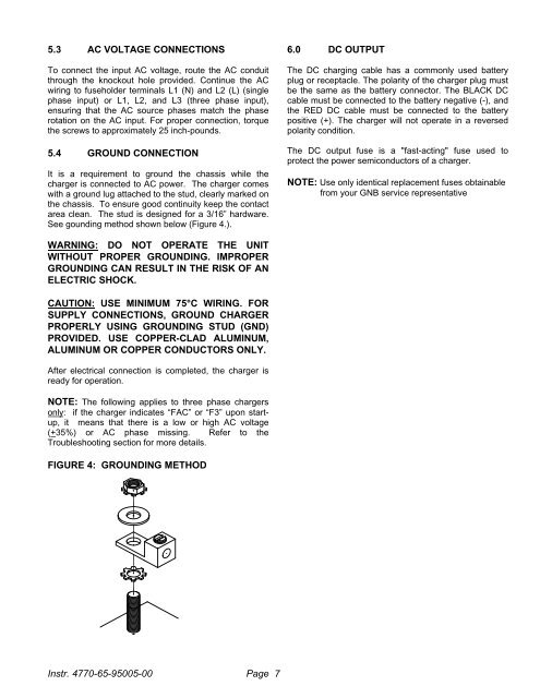
5.4 GROUND CONNECTION<br />
It is a requirement to ground the chassis while the<br />
charger is connected to AC power. The charger comes<br />
with a ground lug attached to the stud, clearly marked on<br />
the chassis. To ensure good continuity keep the contact<br />
area clean. The stud is designed for a 3/16” hardware.<br />
See gounding method shown below (Figure 4.).<br />
6.0 DC OUTPUT<br />
The DC charging cable has a commonly used battery<br />
plug or receptacle. The polarity of the charger plug must<br />
be the same as the battery connector. The BLACK DC<br />
cable must be connected to the battery negative (-), and<br />
the RED DC cable must be connected to the battery<br />
positive (+). The charger will not operate in a reversed<br />
polarity condition.<br />
The DC output fuse is a "fast-acting" fuse used to<br />
protect the power semiconductors of a charger.<br />
NOTE: Use only identical replacement fuses obtainable<br />
from your GNB service representative<br />
WARNING: DO NOT OPERATE THE UNIT<br />
WITHOUT PROPER GROUNDING. IMPROPER<br />
GROUNDING CAN RESULT IN THE RISK OF AN<br />
ELECTRIC SHOCK.<br />
CAUTION: USE MINIMUM 75°C WIRING. FOR<br />
SUPPLY CONNECTIONS, GROUND CHARGER<br />
PROPERLY USING GROUNDING STUD (GND)<br />
PROVIDED. USE COPPER-CLAD ALUMINUM,<br />
ALUMINUM OR COPPER CONDUCTORS ONLY.<br />
After electrical connection is completed, the charger is<br />
ready for operation.<br />
NOTE: The following applies to three phase chargers<br />
only: if the charger indicates “FAC” or “F3” upon startup,<br />
it means that there is a low or high AC voltage<br />
(+35%) or AC phase missing. Refer to the<br />
Troubleshooting section for more details.<br />
FIGURE 4: GROUNDING METHOD<br />
Instr. 4770-65-95005-00 Page 7