SCR100 Charger - Exide Technologies
SCR100 Charger - Exide Technologies
SCR100 Charger - Exide Technologies

Create successful ePaper yourself
Turn your PDF publications into a flip-book with our unique Google optimized e-Paper software.
2.0 INTRODUCTION<br />
The GNB <strong>SCR100</strong> battery chargers are convection<br />
cooled, solid state, micro-processor controlled SCR<br />
regulated chargers designed to make battery charging<br />
simple. They are factory set to charge sealed lead-acid<br />
batteries but it may be configured by a GNB service<br />
representative to charge flooded lead-acid batteries.<br />
The charger has a comprehensive self-checking<br />
diagnostic program to control all charger functions,<br />
monitor the quality of charge and check its own safety<br />
conditions. Large easy to read LEDs, three button<br />
keypad and LED display report on charger and battery<br />
status.<br />
3.0 RECEIVING CHARGER<br />
Examine the charger thoroughly before using, to make<br />
sure that no parts have been loosened or damaged<br />
during shipment. Check the contents of the package<br />
against the delivery slip before disposing of the shipping<br />
package. If any shipping damage or partial loss is<br />
found, file a claim with the carrier without delay and take<br />
any necessary steps to protect your rights. Before<br />
installing check that the charger nameplate data<br />
corresponds to the packing slip and to the model<br />
specified on the original sales order.<br />
The <strong>SCR100</strong> chargers are delivered on skids for easy<br />
handling using a fork lift truck.<br />
4.0 LOCATION AND INSTALLATION OF<br />
CHARGER<br />
Proper installation is important in order to achieve good<br />
charger performance and long troublefree operation and<br />
to prevent damage to the charger and batteries. The<br />
charger should be located in a clean, cool, normal<br />
ambient room temperature (between +45°F/7.2°C and<br />
90°F/32.2°C) dry and well ventilated area. In order to<br />
permit free air flow for convection cooling allow four<br />
inches minimum between the charger and any wall, six<br />
inches from other equipment, and never store anything<br />
beneath and on top of the charger.<br />
4.1 STACKING<br />
When stacking chargers on top of each other, ensure<br />
that cabinets are bolted together using properly sized<br />
black #1/4-20 UNC hardware provided in all four corners<br />
on top cover. The floor mounting must be done with<br />
#3/8-16 UNC bolts (steel rack) or #3/8 lag screws and<br />
anchors (concrete floor). All charger models with a Z,<br />
<strong>SCR100</strong>-XX-XXXT1Z OR <strong>SCR100</strong>-XX-XXXS1Z, can be<br />
stacked to a maximum of three high.<br />
WARNING: THE ABOVE PROCEDURES MUST<br />
BE FOLLOWED EXACTLY TO AVOID INJURY<br />
OR RISK OF ELECTRIC SHOCK.<br />
WARNING: TO REDUCE THE RISK OF FIRE,<br />
INSTALL BATTERY CHARGER ON A FLOOR OF<br />
NON-COMBUSTIBLE MATERIAL SUCH AS<br />
STONE, BRICK, CONCRETE OR METAL. IF<br />
THIS IS NOT AVAILABLE, A FLOOR PLATE OF<br />
AT LEAST 1.43mm GALVANIZED OR 1.6mm<br />
UNCOATED STEEL EXTENDED AT LEAST<br />
150mm BEYOND THE EQUIPMENT ON ALL<br />
SIDES MUST BE INSTALLED.<br />
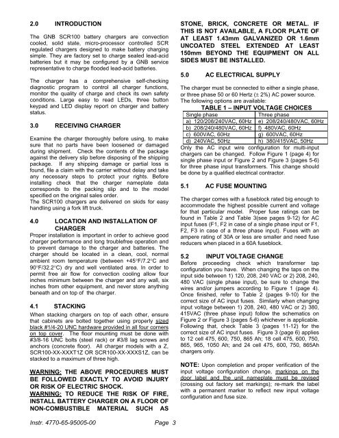
5.0 AC ELECTRICAL SUPPLY<br />
The charger must be connected to either a single phase,<br />
or three phase 50 or 60 Hertz (± 2%) AC power source.<br />
The following options are available:<br />
TABLE 1 – INPUT VOLTAGE CHOICES<br />
Single phase<br />
Three phase<br />
a) 120/208/240VAC, 60Hz e) 208/240/480VAC, 60Hz<br />
b) 208/240/480VAC, 60Hz f) 480VAC, 60Hz<br />
c) 600VAC, 60Hz g) 600VAC, 60Hz<br />
d) 240VAC, 50Hz h) 380/415VAC, 50Hz<br />
Only the AC input wire configuration for multi-input<br />
chargers can be changed. Follow Figure 1 (page 4) for<br />
single phase input or Figure 2 and Figure 3 (pages 5-6)<br />
for three phase input transformers. This change should<br />
be done by a qualified electrical contractor.<br />
5.1 AC FUSE MOUNTING<br />
The charger comes with a fuseblock rated big enough to<br />
accommodate the highest possible current and voltage<br />
for that particular model. Proper fuse ratings can be<br />
found in Table 2 and Table 3(see pages 9-12) for AC<br />
input fuses (F1, F2 in case of a single phase input or F1,<br />
F2, F3 in case of a three phase input). Fuses with an<br />
ampere rating of 30A or less are smaller and need fuse<br />
reducers when placed in a 60A fuseblock.<br />
5.2 INPUT VOLTAGE CHANGE<br />
Before proceeding check which transformer tap<br />
configuration you have. When changing the taps on the<br />
input side between 1) 120, 208, 240 VAC or 2) 208, 240,<br />
480 VAC (single phase input), be sure to change the<br />
wires and/or jumpers according to Figure 1 (page 4).<br />
Once finished, refer to Table 2 (pages 9-10) for the<br />
correct size of AC input fuses. Similarly when changing<br />
input voltage between 1) 208, 240, 480 VAC or 2) 380,<br />
415VAC (three phase input) follow the schematics on<br />
Figure 2 or Figure 3 (pages 5-6) whichever is applicable.<br />
Following that, check Table 3 (pages 11-12) for the<br />
correct size of AC input fuses. Figure 3 (page 6) applies<br />
to 12 cell 475, 600, 750, 865 Ah; 18 cell 475, 600, 750,<br />
865, 965, 1050 Ah; and 24 cell 475, 600, 750, 865Ah<br />
chargers only.<br />
NOTE: Upon completion and proper verification of the<br />
input voltage configuration change, markings on the<br />
door label and the unit nameplate must be revised<br />
(crossing out factory set markings); re-mark the label<br />
with a permanent marker to reflect new input voltage<br />
configuration and fuse size.<br />
Instr. 4770-65-95005-00 Page<br />
3