csf_mini.pdf - Harmonic Drive LLC
csf_mini.pdf - Harmonic Drive LLC
csf_mini.pdf - Harmonic Drive LLC

You also want an ePaper? Increase the reach of your titles
YUMPU automatically turns print PDFs into web optimized ePapers that Google loves.
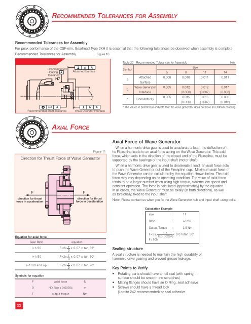
RECOMMENDED TOLERANCES FOR ASSEMBLY<br />
Recommended Tolerances for Assembly<br />
For peak performance of the CSF-min, Gearhead Type 2XH it is essential that the following tolerances be observed when assembly is complete.<br />
Recommended Tolerances for Assembly Figure 10<br />
Recommended<br />
Housing A<br />
Tolerance<br />
H7<br />
ø c A<br />
Recommended Shaft Tolerance<br />
a A<br />
Attached Surface<br />
b A<br />
Wave Operator Interface<br />
Table 20 Recommended Tolerances for Assembly<br />
Nm<br />
Symbol<br />
a<br />
b<br />
c<br />
Size<br />
5 8 11 14<br />
Attached 0.008 0.010 0.011 0.011<br />
Surface<br />
Wave Generator 0.005 0.012 0.012 0.017<br />
Interface (0.006) (0.007) (0.008)<br />
0.005 0.015 0.015 0.030<br />
Concentricity<br />
(0.006) (0.007) (0.016)<br />
* The values in parenthesis indicate that the wave generator does not have an Oldham coupling.<br />
AXIAL FORCE<br />
Direction for Thrust Force of Wave Generator<br />
F<br />
direction for thrust<br />
force in acceleration<br />
F<br />
Figure 11<br />
direction for thrust<br />
force in deceleration<br />
Axial Force of Wave Generator<br />
When a harmonic drive gear is used to accelerate a load, the deflection of t<br />
he Flexspline leads to an axial force acting on the Wave Generator. This axial<br />
force, which acts in the direction of the closed end of the Flexspline, must be<br />
supported by the bearings of the input shaft (motor shaft).<br />
When a harmonic drive gear is used to decelerate a load, an axial force acts<br />
to push the Wave Generator out of the Flexspline cup. Maximum axial force of<br />
the Wave Generator can be calculated by the equation shown below. The axial<br />
force may vary depending on its operating condition. The value of axial force<br />
tends to be a larger number when using high torque, extreme low speed and<br />
constant operation. The force is calculated (approximately) by the equation.<br />
In all cases, the Wave Generator must be axially (in both directions), as well<br />
as torsionally, fixed to the input shaft.<br />
Note: Please contact us when you fix the Wave Generator hub and input shaft using bolts.<br />
Calculation Example<br />
size : 11<br />
Ratio : i=1/50<br />
Output Torque : 3.5 Nm<br />
Equation for axial force<br />
Gear Ratio<br />
equation<br />
i=1/30 F=2x T x 0.07 x tan 32º<br />
D<br />
i=1/50 F=2x T x 0.07 x tan 30º<br />
D<br />
i=1/80 and up F=2x T x 0.07 x tan 20º<br />
D<br />
Symbols for equation<br />
F axial force N<br />
D HD Size x 0.00254 m<br />
T output torque Nm<br />
F=2x 3.5 x 0.07xtan 30º<br />
(11x0.00254)<br />
F=10N<br />
Sealing structure<br />
A seal structure is needed to maintain the high durability of<br />
harmonic drive gearing and prevent grease leakage.<br />
Key Points to Verify<br />
• Rotating parts should have an oil seal (with spring),<br />
surface should be smooth (no scratches)<br />
• Mating flanges should have an O Ring, seal adhesive<br />
• Screws should have a thread lock<br />
(Loctite 242 recommended) or seal adhesive.<br />
22