M - tormatic
M - tormatic
M - tormatic

You also want an ePaper? Increase the reach of your titles
YUMPU automatically turns print PDFs into web optimized ePapers that Google loves.
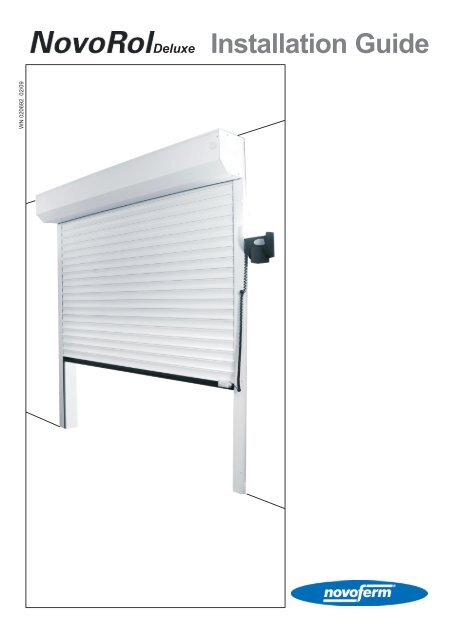
Deluxe<br />
Installation Guide<br />
WN 020692 02/09
6 mm Masonry<br />
6 mm Metal<br />
12.5 mm Metal<br />
0<br />
1<br />
2a<br />
Ø 6 mm<br />
18 mm<br />
Ø 12.5 mm<br />
6 mm<br />
Ø 6 mm<br />
90 mm<br />
Ø 6 mm<br />
90 mm<br />
12.5 mm<br />
*approx. 400 mm<br />
100 mm<br />
*approx. 400 mm<br />
100 mm<br />
2b<br />
2c
2d<br />
3a<br />
40 mm<br />
40 mm<br />
80 mm<br />
80 mm<br />
6 mm<br />
3b<br />
3c<br />
3d<br />
3e
6 mm<br />
1.<br />
6 mm<br />
2<br />
1 , 5 0 m<br />
1<br />
4a<br />
4b 5a<br />
5<br />
230V~ N PE 12V SE TEST LS STOP IMP. ANT<br />
M<br />
230V<br />
~<br />
GND<br />
PE<br />
6<br />
K M J I H G F E
M<br />
PE<br />
BL<br />
UP<br />
DOWN<br />
yellow/green<br />
blue<br />
brown<br />
black<br />
7
own<br />
green<br />
white<br />
I<br />
green brown white<br />
green brown white<br />
8
I<br />
h<br />
I<br />
H<br />
G F E<br />
LS 5 LS 5<br />
1 2 3<br />
+V -V NC C NO<br />
POTHO CELLS: TYPE LS 5<br />
CABLE TYPE: J-YY 2 x 2 x 0,6<br />
9
10a 10b 10c<br />
10d 10e 11a<br />
A<br />
a C B<br />
D<br />
11b
2 sec<br />
12a 12b 13a<br />
13b<br />
13d<br />
+ -<br />
+ -<br />
14a 11c<br />
14b
+ -<br />
+ -<br />
-<br />
+<br />
14c<br />
14d<br />
-<br />
+<br />
-<br />
+<br />
14e 11c<br />
14f<br />
14g<br />
14h
16<br />
F< 400N<br />
F=<br />
15<br />
17<br />
LIGHT<br />
DO<br />
UP<br />
N<br />
PE<br />
Receiverboard<br />
12V<br />
SE<br />
GND<br />
PC<br />
STOPA IMP ANT<br />
N L LIGHT<br />
S2<br />
18<br />
Special settings<br />
The setting can be altered via Dip switches.<br />
S1<br />
S8<br />
1 2<br />
S2<br />
S2<br />
Safety Edge<br />
Input I is configurated for a Optical Safety Edge.<br />
(factory setting)<br />
Input I is configurated for a<br />
Electic Saftey Edge with 1K2 resistor.<br />
H<br />
I<br />
c<br />
1 2<br />
S3<br />
1K2<br />
Automatic Closing Mode<br />
Press Button to open the door. After the desired hold open time<br />
set switch S3 on. In this mode photo cells are required.<br />
Early warning phase<br />
The early warning phase is set, the light starts 4 seconds before<br />
the operator starts up.<br />
18<br />
S4<br />
S6<br />
S6<br />
S7<br />
Protection against drawing in<br />
An external photocell safety device to detect a person who is in<br />
danger to be drawn in.<br />
If the photocell is interrupted whilst the door is closing,or<br />
opening thedoor stops immediately.<br />
Safety edge<br />
If the closing door encounters an obstruction, the operator stops<br />
and causes the door reopensto its top end-of-travel position.<br />
The opening door encounters an obstruction, the operator stops<br />
immediately.<br />
19
Table of Contents<br />
• General Information<br />
- Safety<br />
- Explanation of symbols<br />
- Occupational safety<br />
- Hazards that can result from this product<br />
- Spare parts<br />
- Changes and modifications to the product<br />
- Dismantling<br />
- Disposal<br />
- Data plate<br />
- Packaging<br />
- Terms of warranty<br />
• Installation Instructions<br />
• Operating Instructions<br />
• Maintenance and Checks<br />
• Trouble-shooting Guide<br />
• Diagnostic Display<br />
• Declaration of Conformity<br />
- Technical data<br />
• Inspection Log Book<br />
Deluxe<br />
• General Information<br />
• Safety<br />
Before commencing any work on the product,<br />
carefully read through the Operating Instructions<br />
from start to finish, in particular the section entitled<br />
"Safety" and the related safety advice. It is<br />
important for you to have fully understood what<br />
you have read. This product could prove<br />
hazardous if not used properly as directed or in<br />
accordance with the regulations.<br />
Any damage occurring as a result of noncompliance<br />
with these instructions shall exempt<br />
the manufacturer from all liability.<br />
• Explanation of symbols<br />
WARNING: IMMINENT DANGER<br />
This symbol indicates that instructions are<br />
being given which, if not observed, could<br />
lead to serious injury.<br />
WARNING! Risk for electric shock<br />
Installation only be performed by certified<br />
eletricians.<br />
This symbol indicates that instructions are<br />
being given which, if not observed, could<br />
! lead to malfunctions and / or failure of the<br />
operator.<br />
0<br />
Reference to text and figure<br />
• Occupational safety<br />
By following the safety advice and instructions<br />
provided in this Operating Manual, injury to<br />
persons and damage to property whilst carrying<br />
out work with and on the product can be avoided.<br />
Failure to observe the safety advice and<br />
instructions provided in this Operating Manual as<br />
well as the accident prevention regulations and<br />
general safety regulations applicable to the range<br />
of use shall exempt the manufacturer or its<br />
authorized representative from all liability and<br />
render any damage claims null and void.<br />
• Hazards that can result from this product<br />
The product has undergone a risk assessment.<br />
The design and execution of the product based on<br />
this corresponds to state-of-the-art technology.<br />
When used properly in accordance with the<br />
regulations, the product is reliable and safe to<br />
operate. Nevertheless, a residual risk always<br />
remains.<br />
The product runs at a high voltage. Before<br />
commencing any work on electrical systems,<br />
please observe the following:<br />
1. Disconnect from the power supply<br />
2. Safeguard against a power restart<br />
3. Establish that electricity supply is cut off<br />
• Spare parts<br />
Only use the manufacturer’s genuine spare<br />
parts. Wrong or faulty spare parts can<br />
cause damage, malfunctions or even a<br />
total failure of the product.<br />
• Changes and modifications to the product<br />
To prevent hazards and ensure optimum<br />
performance, the product may not be subjected to<br />
any changes, modifications or conversions that<br />
have not been expressly approved by the<br />
manufacturer.<br />
GB<br />
• Dismantling<br />
Dismantling takes place in reverse sequence to the<br />
Installation Instructions.<br />
• Disposal<br />
Observe the corresponding country-specific<br />
regulations.<br />
• Data plates<br />
The data plate for the control is located on the side<br />
of the control box. Observe the specified power<br />
rating.<br />
The data plate for the door is placed on the curtain.<br />
• Packaging<br />
Always dispose of the packaging materials in an<br />
environmentally-sound manner and in accordance<br />
with the local regulations on disposal.<br />
• Terms of warranty<br />
The purchaser is granted a warranty covering the<br />
safe and reliable operation of the Novoferm garage<br />
door for a period of 10 years from the date of<br />
purchase. This warranty is conditional on the<br />
regular inspection and maintenance of the product<br />
in accordance with the installation manual supplied<br />
with the door. During the guarantee period the<br />
manufacturer undertakes to repair, without charge,<br />
any product which has suffered a proven failure of<br />
its safe and reliable operation provided that the<br />
springs, wire cables, tracks, guide rollers and<br />
hinges have been inspected regularly (at least<br />
once a year) and maintained correctly, including<br />
replacement of wear items when required.<br />
NovoRol garage door systems are guaranteed<br />
against any form of manufacturing defects for a<br />
period of 2 years from the date of purchase. The<br />
finish of white powder coated doors is guaranteed<br />
for a period of 2 years.<br />
In the case of textured woodgrain finished doors,<br />
the exterior finish is guaranteed to provide an<br />
effective weatherproof membrane which will resist<br />
perforation of the NovoRol door from the weather<br />
side due to corrosion for 10 years. Furthermore,<br />
colour change or fade to the exterior surface will<br />
be limited and uniform for the full 10 year period.<br />
NovoRol electric operators are guaranteed against<br />
any form of manufacturing defect for a period of 5<br />
years for mechanical elements, motors and<br />
transformers. The motor control unit is guaranteed<br />
for 3 years. Remote control accessories and parts<br />
are guaranteed for a period of 2 years.<br />
Manufacturer:<br />
Novoferm Europe Limited<br />
Brooke Park, Epsom Avenue, Handforth Dean,<br />
Wilmslow, Cheshire, SK9 3PW<br />
Tel: 0161 486 0066 (Garage Door Division)<br />
These Installation, Operating and Maintanance Instructions must be retained and kept safe throughout the product`s entire service life.
GB<br />
• Installation Instructions<br />
Repairs and adjustments should only be<br />
performed by an authorized Novoferm<br />
dealer.<br />
Incorrect installation can put the safety of persons<br />
at risk or cause damage to property! Improper<br />
installation shall exempt the manufacturer from all<br />
liability.<br />
Preparing for installation<br />
1. To connect to the mains, a power point must be<br />
installed on site - the included mains lead is<br />
approx. 1 m long.<br />
2. Check the supplied screws and wall plugs to<br />
ensure that these are suitable for the structural<br />
conditions on site.<br />
3. Choose the installation side of the tubular motor<br />
in accordance with the structural conditions on<br />
site.<br />
4. For garages without a second entrance, an<br />
emergency opening device is required<br />
(accessory).<br />
0<br />
Required tools<br />
- Drilling machine with 6 mm masonry,<br />
6 mm and 12.5 mm metal drill<br />
- Sturdy side cutter<br />
- Slotted screwdriver, 3 mm wide<br />
- Philips screwdriver, size 2 x 100 mm<br />
- Spirit level<br />
- Adjustment stick<br />
1<br />
2<br />
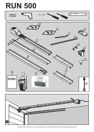
Remove the cover<br />
Preparing the guides<br />
1. Identify front and back sides of the guides refer<br />
to the diagram 2a and lay guides on the back.<br />
2. According the distances in the drawing shown.<br />
Pilot drill guides with 6mm drill bit. All the way<br />
though.<br />
3. Drill the face of track with 12.5 mm drill bit<br />
WARNING! Do not drill all the way through.<br />
4. Slide guides onto the end plates as shown.<br />
3<br />
Mounting the door<br />
Mark out and position the guides, plumb sides and<br />
top.<br />
Fix guides to the wall with appropriate fixings.<br />
Fix back box to the wall, using additional fixings<br />
across the full width of the box to reduce<br />
deflection.<br />
Ensure all bolt heads screws etc, housed inside<br />
the Novoshield canopy do not encroach into the<br />
roller shutter coiling area.<br />
Important!<br />
DO NOT ATTEMPT TO INSTALL THE SHUTTER<br />
CURTAIN AT THIS STAGE!<br />
4<br />
Fastening the control unit<br />
Mount the control unit onto the side wall.<br />
1. At side from the door and 1.50m from the floor,<br />
mark the spot for the first plug hole,<br />
2. drill the hole, insert the plug but do not screw the<br />
screw in fully.<br />
3. Place the control unit with key hole onto the<br />
screw head.<br />
4. Align the unit and mark the remaining fixing<br />
holes, drill holes, plug and fasten with screws<br />
4.2 x 32.<br />
5<br />
Mains connecting lead<br />
At the back of the control unit there is a chamber in<br />
which, if required, the excess mains lead can be<br />
stowed.<br />
1. Wind up the excess cable and place in the<br />
chamber.<br />
2. Fasten the cable clips with self-tapping screws.<br />
6<br />
Connecting plan / aligning the aerial<br />
Instructions:<br />
! or volt-free relay outputs.<br />
E. Connection for aerial<br />
Do not connect any current-carrying<br />
cables, only connect volt-free push buttons<br />
Route the aerial on the housing exit upwards.<br />
When using an external aerial, the shielding<br />
must be assigned to the adjacent terminal (F, on<br />
right).<br />
F. Connection for external impulse generator<br />
(accessories, e.g. key switch or digital coderG.<br />
Input STOP A<br />
Connection for safety devices (accessories, e.g.<br />
Emergency Button). An interruption at this input<br />
end causes the door to stop during the opening<br />
or closing phase or prevents the operator from<br />
starting up in either direction.<br />
H. Input STOP B<br />
Connection for safety devices (accessories, e.g.<br />
one-way photocell). An interruption at this input<br />
end causes the operator to automatically<br />
change direction during the closing phase only.<br />
I. Optical Safety Egde OSE<br />
- Voltage supply12 Vdc<br />
(e.g. for one-way photocell), connection can<br />
take a max. load of 60 mA (do not exceed!)<br />
- Signal Input OSE<br />
- GND<br />
J. Plug-in base for radio receiver<br />
K Connection for an external light with protectetive<br />
insulation or signal lamp, max 500W).<br />
M Motor connector<br />
- Down<br />
- Up<br />
- Common<br />
- PE<br />
1. Loosen both screws on the terminal cover and<br />
pull the cover to the front to remove.<br />
2. Connect corresponding cables according to the<br />
connection diagram.<br />
3. Put the terminal cover back on again by feeding<br />
the back end of the cover under the guides of<br />
the control unit and<br />
4. then screw back in place.<br />
7 Connecting the motor cable<br />
Lay the motor cable within the formed recess at the<br />
back of the control unit and secure, using the cable<br />
clips and screws provided.<br />
Connect the wires according<br />
to the drawing.<br />
brown – upward travel,<br />
black – downward travel<br />
blue – neutral<br />
yellow/green – PE<br />
The brown and black wires will have to be reversed<br />
for a left hand motor.<br />
8<br />
Wiring the optical safety egde<br />
1. Disconnect control panel from mains supply<br />
before wiring the safety edge<br />
2. Connect the sensor cables together with the<br />
coiled cable:<br />
3. Hold up the coiled cable in a vertical position in<br />
height of the control unit.<br />
4. Hold the clamp against the guide, mark the spot,<br />
drill, screw to the guide using screw 4.2 x 25.<br />
5. Connect the coiled cable as in the drawing on<br />
terminal i.<br />
6. Now re-connect the mains power supply to the<br />
control panel.<br />
9<br />
Installing photo cells (Option)<br />
Where door systems are used by the<br />
public or are impulse-operated out of sight<br />
of the door, a photocell must be installed,<br />
or if the operation mode of the controll unit<br />
is “automatic closing”.<br />
Install photo cell Novoferm LS5 in a hight of 20-<br />
30cm. Observe a distance to the door regarding<br />
the coiled cable.<br />
Remove the bridge on terminal (h) and route the<br />
cable and wire according the drawing.<br />
10<br />
Lamp<br />
1. Screw in light bulb (max. 40W/230V).<br />
2. From above, slot lamp cover into side guides<br />
until it engages.<br />
3. Plug into mains.<br />
11<br />
Control elements<br />
The control elements for programming the door<br />
operator are located behind the white cover. The<br />
cover can be opened with a screwdriver.<br />
Once the operator has been programmed, the<br />
cover is reclosed and serves as an interior pushbutton<br />
(figure 16).<br />
A. The numerical display serves to indicate the<br />
menu stage, the respectively set value and the<br />
error/fault diagnosis.<br />
a. The incremental display, lights up to indicate<br />
readiness for operation.<br />
B. Button serves as a START button.<br />
C.Button<br />
serves as a "DOWN" button.<br />
D. Button serves as “Prorgramming<br />
Transmitter”<br />
After power on the controller is checking itself.<br />
Successively middle line, bottom line and dot<br />
shine on the display.<br />
12 Menu stage 1: programming the starting<br />
function for the hand transmitter<br />
- Briefly press button .<br />
A "1" flashes all 2,5 seconds<br />
- keep the button of the hand transmitter, with<br />
which you would like to start the operator later,<br />
pressed for approx. 1 second.<br />
- As soon as the code has been read in, this is<br />
acknowledged by “1” is still displayed as long as<br />
the transmitter button is pressed.<br />
Further hand transmitters (up to a max. of 60<br />
button codes) can be programmed.<br />
13 Safety Brake & Curtain Connection<br />
Ensure the safety brake is fully disengaged by<br />
pressing the upward control button on the control<br />
box to make one full rotation of the barrel.<br />
1. Now press and hold the downward travel button<br />
and rotate the barrel until it stops.<br />
2. Now connect the curtain to the tube using the<br />
anti lift hinges provided.<br />
14 Limit Settings<br />
Do not use the manual override prior to<br />
setting the limit switches.<br />
! Only use the limit setting tool provided.<br />
Do not use power tools to adjust the limit<br />
position.<br />
Do not hose the motor with water.<br />
If the motor stops working, wait for 20 mins to<br />
allow the motor to cool before further operations.<br />
These Installation, Operating and Maintanance Instructions must be retained and kept safe throughout the product`s entire service life.
The tubular geared motor has intergral electromechanical<br />
limit switches that cut off the power at<br />
a position corresponding to the Fully Open &<br />
Closed position of the door.<br />
Both the upper and lower limit settings for the<br />
curtain travel are pre-set in the factory to suit the<br />
opening height of each individual door, however<br />
fine tuning will be required, using the following<br />
proceedure.<br />
Whilst toggling between the upward/downward<br />
control buttons on the control box, make<br />
adjustments to the limit travel settings as follows:<br />
50Nm MOTOR SETTINGS (Octagonal Head)<br />
LEFT HAND MOTOR<br />
14a. Adjust WHITE limit CLOCKWISE to increase<br />
the travel of bottom limit.<br />
14b. Adjust RED limit CLOCKWISE to increase the<br />
travel of top limit.<br />
RIGHT HAND MOTOR<br />
14c. Adjust WHITE limit ANTI CLOCKWISE to<br />
increase the travel of the top limit<br />
14d. Adjust RED limit ANTI CLOCKWISE to<br />
increase the travel of the bottom limit.<br />
100Nm MOTOR SETTINGS (Square Head)<br />
LEFT HAND MOTOR<br />
14e. Adjust WHITE limit ANTI CLOCKWISE to<br />
increase the travel of bottom limit.<br />
14f. Adjust RED limit ANTI CLOCKWISE to<br />
increase the travel of top limit.<br />
RIGHT HAND MOTOR<br />
14g. Adjust WHITE limit CLOCKWISE to increase<br />
the travel of the top limit.<br />
14h. Adjust RED limit CLOCKWISE to increase the<br />
travel of the bottom limit.<br />
NOTE!<br />
WHEN SETTING THE LIMIT TRAVEL, DO NOT<br />
OVER ADJUST THE DOWNWARD LIMIT<br />
SCREW AS THIS COULD CAUSE SERIOUS<br />
DAMAGE TO THE ANTI LIFT HINGES.<br />
WHEN ADJUSTING THE UPWARD TRAVEL<br />
LIMIT REMEMBER THAT THE SAFETY EDGE<br />
RELAY BOX MOUNTED ON THE BOTTOM RAIL<br />
SHOULD PROJECT BELOW THE NOVOSHIELD<br />
CANOPY.<br />
15 Re-fit the Novoshield<br />
•Operating Instructions<br />
Information regarding the operating<br />
instructions<br />
These operating instructions describe how to use<br />
the product properly and safely. The safety advice<br />
and instructions as well as the local health and<br />
safety regulations and general safety regulations<br />
for the range of use must be observed.<br />
All persons using the door system must<br />
be shown how to operate it properly and<br />
safely.<br />
1. In the interest of your safety and others, this<br />
door must be operated by users familiar with its<br />
operation.<br />
2. When operating the door do not place fingers<br />
near or in guides or another moving part at any<br />
time.<br />
3. The person operating the door must have it in<br />
sight at any times during this operation<br />
particularity if is automatic operation.<br />
4. Do not permit children to play with the garage<br />
door or electrical controls.<br />
5. Do not attach any objects to, or make any<br />
modifications to the door as this may cause<br />
damage and/or physical injury.<br />
6. Operate the door only when adjusted and free<br />
from obstruction.<br />
7. Should the door become difficult to operate or<br />
completely inoperable, call an authorized<br />
Novoferm dealer. Repairs and adjustments<br />
should only be undertaken by qualified person.<br />
8. Every 6 months check a tighten and loose<br />
fixings.<br />
9. Periodically clean your door with warm water,<br />
allow dry naturally. Do not use abrasive or<br />
caustic based cleaners. Bird droppings are<br />
caustic please remove upon detection.<br />
10.Your new garage door needs an annual service<br />
by an authorized Novoferm dealer to maintain<br />
the CE mark and warranty.<br />
16 Internal impulse generators<br />
The cover on the control unit is used as an impulse<br />
generator for opening and closing from inside the<br />
garage. Briefly press the cover and the operator<br />
starts up<br />
Functional sequence<br />
The garage door operator can be actuated by<br />
push-button on the control unit (figure 16) or by<br />
other impulse generators, such as hand<br />
transmitters, key switches etc. It is only necessary<br />
to generate a short, sharp impulse.<br />
- Initial impulse:<br />
Operator starts up and causes the door to travel<br />
to the set OPEN or CLOSE end-of-travel<br />
positions.<br />
- Impulse generated whilst the door is in motion:<br />
Door stops<br />
- A new impulse:<br />
Door continues to move but in the opposite<br />
direction.<br />
Optical safety edge<br />
If the closing door encounters an obstruction, the<br />
operator stops and causes the reverses direction<br />
for approx. 2 second in order to clear the<br />
obstruction.<br />
The door can be closed again by generating a new<br />
impulse.<br />
Photocell defective<br />
If the photocell is interrupted whilst the door is<br />
closing, the door stops and reopens to its top endof-travel<br />
position.<br />
An interruption whilst the door is opening has no<br />
effect.<br />
Lighting<br />
The lighting switches on automatically whenever a<br />
start impulse is generated and switches off again<br />
after the set time phase (factory setting approx. 90<br />
seconds).<br />
Changing the light bulb<br />
Pull out the mains plug and open the lamp shade<br />
using a Phillips screwdriver size 2 x 100. Replace<br />
the light shade (230 V, 40 W, cap E27) and screw<br />
the lamp cover back on again.<br />
Signal light<br />
If a signal light for signalling the opening and<br />
closing phases is installed, this flashes together<br />
with the lamp in the operator as soon as a start<br />
impulse is generated. The operator starts with a<br />
time delay in accordance with the set early warning<br />
phase (see Special Settings).<br />
Hand transmitters<br />
- Programming further hand transmitters:<br />
(figures 12a and 12b).<br />
- Changing the battery: slide back the battery<br />
compartment cover on the hand transmitter.<br />
Take out the battery.<br />
- Insert a new battery. Be sure to pole correctly!<br />
Slide the cover back on.<br />
Empty batteries must be disposed of<br />
separately (toxic waste)!<br />
19 Hand crank<br />
In case of a power faifure use the hand crank to<br />
open and close the door manually (figure 19).<br />
Do not overwind, this can cause damage<br />
! to auto locks.<br />
• Maintenance / Checks<br />
For your own safety we recommend<br />
that the door system be checked by a<br />
specialist after initial installation and<br />
then regularly at intervals of 1 year<br />
minimum.<br />
17 Checking the force limit facility<br />
- Place an obstruction (e. g. operator's cardboard<br />
box) underneath the door's cosing edge.<br />
- Starting from the OPEN end-of-travel position,<br />
actuate the door to close.<br />
- The door travels towards the obstruction, stops<br />
and travels back for approx. 2 seconds in order<br />
to clear the obstruction.<br />
The door system must be checked before initial<br />
operation and at least once a year thereafter. In<br />
the process, the force limiting device (figure 17)<br />
must be tested!<br />
CAUTION! If the closing force is set too<br />
high, this can result in injury to persons and<br />
damage to property.<br />
The opening force can be re-adjusted in menu<br />
stage 5, the closing force in menu stage 6.<br />
These Installation, Operating and Maintanance Instructions must be retained and kept safe throughout the product`s entire service life.
• Trouble-shooting Guide<br />
Important note: when working on the operator, always pull out the mains plug beforehand !!!<br />
Malfunction Possible causes Remedy<br />
Door does not open/close full. Door mechanics have altered. Have the door checked.<br />
Door does not open/close fully. Readjust travel limit 13 and 14.<br />
Travel limit is incorrectly set.<br />
After closing, the door opens again slightly. Door blocks shortly before reaching the closed Remove the obstruction.<br />
position. Readjust closed travel limit 13 ..<br />
Travel limit is incorrectly set.<br />
Door does not respond on impulse from the Battery in the hand transmitter is flat. Replace battery in the hand transmitter.<br />
hand transmitter - but does respond to push- Aerial not fitted. Plug in / align aerial..<br />
buttons or other impulse generators. No hand transmitter programmed. Programme the hand transmitte 12<br />
Door does not respond to impulse from hand See diagnostic display. See diagnostic display.<br />
transmitter nor to other impulse generators.<br />
Insufficient range of hand transmitter. Battery in the hand transmitter is flat. Replace battery in the hand transmitter.<br />
Aerial not fitted.<br />
Plug in / align aerial.<br />
On-site screening of the receiving signal.<br />
Connect external aerial (accessories).<br />
Door only works in dead man mode when Safety edge dip switch may be incorrectly set. Set dip switch 1 +2 as per instruction manual.<br />
closing only. .<br />
Door does not stop after hitting an obstacle. Loose wiring from safety edge / photo cells to Check wiring from safety edge / photo calls to<br />
control panel<br />
control panel as per instruction manual.<br />
Damaged safety edge / photo cells..<br />
Renew safety edge / photo cells<br />
The door is going up and down noisily and Drum and motor have come apart. Check that the motor is pushed firmly into the<br />
moving from side to side<br />
drum and is held in with the fixing screw.<br />
I have been using the door constantly but it Motor has over heated. Let the motor rest for 15 minutes [cool down<br />
has suddenly stopped working.<br />
period].<br />
There is a noise coming from the ends of the<br />
drum when the door is operated<br />
There is grit in the sliding brackets.<br />
Clean and oil the sliding brackets.<br />
• Diagnostic Display<br />
During operation the display provides diagnostic information on any possible faults and/or malfunctions<br />
Display State Diagnosis / Remedy<br />
Operator is not ready for operating<br />
Operator is ready for operating<br />
Control main power.<br />
Check internal Fuse 3.15A<br />
Operator is receiving a valid transmitter<br />
code<br />
Operator drives in up direction.<br />
A transmitter is activated.<br />
Operator has got a start impulse.<br />
Operator drives in up direction<br />
Operator drives in close direction<br />
Operator drives in close direction<br />
A transmitter is still activated.<br />
Operator has got a start impulse.<br />
A transmitter is still activated.<br />
Door does not close.<br />
All 2.5 seconds one flash.<br />
All 2.5 seconds two flashes.<br />
Door will not open or close.<br />
Dot flashes once in 2.5 seconds.<br />
Safety edge is activated.<br />
Photocell is activated.<br />
Emergency Stop is activated.<br />
Check imput G. Close this input<br />
Door will not open or close. Safety test has been triggered.<br />
Line and dot flashes consecutive.<br />
Briefly pull out mains plug.<br />
Subject to changes
hereby declares that the<br />
EU Declaration of Conformity<br />
according to EN 13241-1 Doors/Gates Product Standard Annex ZA<br />
Novoferm Europe Limited<br />
Brooke Park - Epsom Avenue<br />
Handforth Dean - Wilmslow<br />
Chehire Sk9 3PW<br />
POWER OPERATED DOOR<br />
NOVOROL<br />
conform to the relevant requirements of the EC Construction Products Directive (89/106/EEC).<br />
Proof of compliance was furnished by the recognized examining body<br />
Bodycote Warrington apt<br />
Key Industrial Park - Fernside Road.<br />
Willenhall, West Midlands UK WV 13 3YA<br />
Furthermore, NovofermEurope declares that the operator conforms to the relevant directives / regulations of the<br />
- EG-Machinery Directive (98/37/EG)<br />
- Low Voltage Directive (73/23/EWG)<br />
- Electromagnetic Compatibility Directive (89/336/CEE)<br />
In the process, the harmonized standards EN13241-1, EN12453 , EN12445 and EN60335-1 were applied.<br />
Wilmslow, 15.06.2008<br />
The undersigned is General Manager of Novoferm Europe.<br />
___________________________<br />
Steve Dickinson<br />
NovoRol Door Data<br />
Resistance to wind load: 2<br />
Thermal resistance: 5.2w/m²k<br />
Water tigthness:: NPD<br />
Air permability: NPD<br />
Power rating: 230V / 50Hz / 3,15A<br />
max. Motor Power: 740W<br />
Short-time duty: 2 min.<br />
Lighting:<br />
230V /40W E27<br />
External lighting: max. 500W<br />
Operating mode: Impulse operation, remote-controlled<br />
Temperature range: - 20°C - +60°C<br />
For dry rooms only<br />
Unique Serial No.: ___________________________ Color: ______________________________<br />
Door Size: ___________________________ Motor Type: ______________________________<br />
Side Address: ___________________________________________________________________________________<br />
WE declare that the guidelines of the manufacturer have been adhered to.<br />
Installing company<br />
Place, date: ____________________________ Signature: ______________________________
Proof of Inspection and Maintenance of the Door System<br />
Date Work performed / necessary measures Inspection carried out Defects rectified<br />
Signature / Address of<br />
the company<br />
Signature / Address of<br />
the company<br />
Initial operation, first inspection<br />
These Installation, Operating and Maintanance Instructions must be retained and kept safe throughout the product`s entire service life.