UK PRODUCT CATALOGUE - Deks.co.uk
UK PRODUCT CATALOGUE - Deks.co.uk
UK PRODUCT CATALOGUE - Deks.co.uk

You also want an ePaper? Increase the reach of your titles
YUMPU automatically turns print PDFs into web optimized ePapers that Google loves.
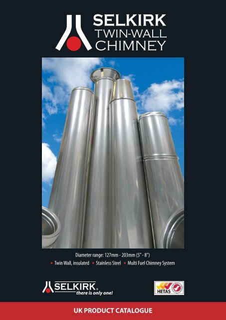
Diameter range: 127mm - 203mm (5” - 8”)<br />
• Twin Wall, insulated • Stainless Steel • Multi Fuel Chimney System<br />
<strong>UK</strong> <strong>PRODUCT</strong> <strong>CATALOGUE</strong>
INTRODUCTION<br />
The Selkirk Twin Wall chimney system is designed for use with oil, gas and solid fuel<br />
when used with the appropriate fire stopping <strong>co</strong>mponents. The system is designed for<br />
gravity flow application. The Selkirk Twin Wall chimney system is available in a range of<br />
diameters and this brochure relates to the 127mm (5”) – 203mm (8”) range.<br />
The system <strong>co</strong>nsists of straight lengths and fittings which are <strong>co</strong>nstructed entirely from<br />
stainless steel and a 25mm (1”) insulated annulus. The external skin is manufactured<br />
from 304 grade matt finish stainless steel and carries the structural load, and the inner<br />
liner is resistant to the often <strong>co</strong>rrosive products of <strong>co</strong>mbustion, and is free to expand or<br />
<strong>co</strong>ntract as flue gas temperatures change. The 316 grade inner liner heats rapidly to<br />
produce a strong draught which ensures that waste gases are exhausted and<br />
<strong>co</strong>ndensation of the harmful products of <strong>co</strong>mbustion is minimised.<br />
The system can be used internally or externally. The relatively low external wall<br />
temperature permits installation with only a 50mm (2”) air gap clearance to<br />
<strong>co</strong>mbustible materials.<br />
Size (internal diameter)<br />
127mm (5”)<br />
152mm (6”)<br />
178mm (7”)<br />
203mm (8”)<br />
Maximum outside diameter<br />
178mm (7”)<br />
203mm (8”)<br />
230mm (9”)<br />
255mm (10”)<br />
KEY DIMENSIONS<br />
COMPOSITION<br />
Lengths and fittings are twin-walled with a 25mm (1”) cavity. The outer casing is joined<br />
to both male and female <strong>co</strong>uplers, while the inner liner is <strong>co</strong>nnected only to the male<br />
<strong>co</strong>upler, as flue gas temperatures vary the inner liner can expand and <strong>co</strong>ntract without<br />
affecting the structural performance.<br />
Selkirk Twin Wall chimney is insulated with rockwool and this high quality insulation has<br />
an optimum and carefully <strong>co</strong>ntrolled density which maintains a relatively high flue gas<br />
temperature throughout the chimney lengths. Lengths and fittings are twist-locked<br />
together with a one eighth turn. Locking bands fit over the two rolled seams at joints<br />
between lengths and fittings and MUST be used.<br />
APPLICATIONS<br />
Typical equipment includes boilers, stoves and heaters. The Selkirk chimney system must<br />
be installed in ac<strong>co</strong>rdance with all appropriate building regulations, <strong>co</strong>des of practice<br />
and manufacturers installation instructions. Selkirk Twin Wall chimney in diameters<br />
127mm (5”) – 203mm (8”) are manufactured to <strong>co</strong>mply with BS4543 parts 2 and 3 and<br />
EN1856-1.<br />
The STC product designation is: T450 N1 D Vm L50045 G(50)<br />
INSTALLATION<br />
Maximum diameter<br />
Size<br />
Installation instructions can be found at www.deks.<strong>co</strong>.<strong>uk</strong> and are provided with all<br />
support <strong>co</strong>mponents. These should be <strong>co</strong>nsulted to accurately determine the<br />
<strong>co</strong>mponents that are required to enable any installation to be <strong>co</strong>rrectly assembled.<br />
Jointing<br />
Lengths and fittings are designed to be installed with the male <strong>co</strong>upling uppermost.<br />
Joints are achieved by placing the female <strong>co</strong>upling over the male <strong>co</strong>upling and making a<br />
one-eighth turn. A Locking band must be used to secure every joint and to ensure a firm<br />
<strong>co</strong>nnection.<br />
Connecting to the appliance<br />
The Adaptor is designed to make the <strong>co</strong>nnection to the appliance flue gas outlet or to a<br />
section of flue pipe to building regulation requirements.<br />
Supports<br />
The weight of the chimney may be carried by a number of different support <strong>co</strong>mponents<br />
depending on whether the chimney is installed internally or externally, and whether it is<br />
supported by the roof, ceiling, floor or external wall. These <strong>co</strong>mponents include the Wall<br />
Support, Ceiling Support and Roof Support. Lateral stability is provided by Wall Bands.<br />
Supporting free-standing chimneys<br />
Where the chimney exceeds 1.5 metres (4.9ft) beyond the last support it must be braced<br />
with a roof brace kit or similar. The bracket should be fitted above a locking band and as<br />
close to the joint as possible.<br />
Roof Support<br />
The Roof Support is designed to support the chimney on the roof timbers and is provided<br />
with adjustable gimbal plates.<br />
Load Bearing data<br />
The weight of the chimney can be borne in a number of ways and this table states the<br />
maximum length of chimney that can be supported by various <strong>co</strong>mponents.<br />
Chimney size (mm)<br />
127 152 178 203<br />
Ceiling Support 6m* 6m* 6m* 6m*<br />
Wall Support<br />
Side Plates Up 15m 15m 15m 15m<br />
Side Plates Down 9m 9m 9m 9m<br />
Teles<strong>co</strong>pic Floor Support 16.7m 16.7m 16.7m 16.7m<br />
Roof Support 9m* 9m* 9m* 9m*<br />
*part of the flue up to a maximum of 6m may be suspended beneath the roof support.<br />
NB: Wall Bands are not load-bearing and must be used at intervals not exceeding 2.5 to<br />
provide lateral stability.<br />
Weight<br />
The weight of each diameter per metre run installed is shown in the table below.<br />
Chimney size (mm)<br />
127 152 178 203<br />
TWIN-WALL CHIMNEY 6.7kg 8.2kg 9.7kg 11.2kg<br />
Clearance<br />
The relatively low external casing temperature experienced in normal operation permits<br />
installation with only 50mm air gap clearance to <strong>co</strong>mbustible materials. Where the Twin-<br />
Wall Chimney passes through a <strong>co</strong>mbustible floor the appropriate firestopping<br />
<strong>co</strong>mponents must be used.<br />
Lengths of Chimney<br />
Standard lengths of 1219mm, 914mm, 610mm, 457mm, 305mm and 152mm and an<br />
adjustable length are available. Individual tables provide details.<br />
Elbows<br />
Building regulations stipulate that where bends are essential, they should be angled at<br />
no more than 45° to the vertical. 15°, 30° and 45° elbows are available.<br />
Floor and Ceiling Penetration<br />
Where the chimney penetrates a <strong>co</strong>mbustible floor or ceiling a 50mm air gap clearance<br />
must be maintained from the outer skin of the chimney to any <strong>co</strong>mbustible materials.<br />
Components are available which cater for such requirements.<br />
Please refer to floor penetration requirements at the rear of this brochure.<br />
Roof Penetrations<br />
Where the chimney penetrates the roof an appropriate flashing should be used. The<br />
Seldek range of flashings is specifically designed for this purpose. To fit, trim the E.P.D.M.<br />
<strong>co</strong>ne to suit the external pipe size using sharp tin snips or scissors, slide down pipe using<br />
water as a lubricant. Dress the aluminium or lead base over the profile of the tiles.<br />
Providing the <strong>co</strong>ne has been cut to the appropriate size, the use of a storm <strong>co</strong>llar or<br />
sealant is not required. If the chimney has a raised seam on the outer skin a small<br />
amount of sili<strong>co</strong>ne sealant should be applied where the chimney penetrates the E.P.D.M.<br />
<strong>co</strong>ne of the flashing.<br />
Termination<br />
Two types of terminations are available. Both have female <strong>co</strong>uplers and are fixed to the<br />
top chimney length and secured with a locking band. The rain cap is a domed stainless<br />
steel cap. The AD <strong>co</strong>wl provides aerodynamic down-draught protection. Both<br />
terminations are deemed to be sacrificial <strong>co</strong>mponents.<br />
1 www.deks.<strong>co</strong>.<strong>uk</strong>
LENGTHS<br />
LENGTHS<br />
ADJUSTABLE LENGTH<br />
The Adjustable Length is designed to provide small<br />
increments in length between 2 fixed points. This<br />
length is not a load bearing <strong>co</strong>mponent, it fits over<br />
the length below and by removing the required<br />
amount of insulation material the length will adjust<br />
from 50mm to 200mm. Because the <strong>co</strong>mponents<br />
application and installation and therefore<br />
performance cannot be accurately <strong>co</strong>ntrolled this<br />
<strong>co</strong>mponent should be installed 300mm from any<br />
<strong>co</strong>mbustible material.<br />
a<br />
Size Part # amm<br />
127 mm 5STC-AL 300<br />
152 mm 6STC-AL 300<br />
178 mm 7STC-AL 300<br />
203 mm 8STC-AL 300<br />
b<br />
LENGTHS<br />
Available in 4 sizes and 6 lengths. They are easy to<br />
assemble and can be <strong>co</strong>mbined to obtain the<br />
required installation height.<br />
Each length is 38mm longer than its effective length.<br />
All lengths are seam welded.<br />
Size Part # amm bmm cmm<br />
127 mm 5STC-L48 1219 127 178<br />
127 mm 5STC-L36 914 127 178<br />
127 mm 5STC-L24 610 127 178<br />
127 mm 5STC-L18 457 127 178<br />
127 mm 5STC-L12 305 127 178<br />
127 mm 5STC-L6 152 127 178<br />
a<br />
TEES<br />
LOCKING BANDS<br />
Inward flanges around the band fit into grooves at<br />
chimney length joints. Reinforces joints of chimney<br />
and prevents accidental un<strong>co</strong>upling. Locking Band is<br />
included with all insulated lengths, tees and elbows.<br />
Size Part # amm<br />
127 mm 5STC-LB 178<br />
152 mm 6STC-LB 203<br />
178 mm 7STC-LB 229<br />
203 mm 8STC-LB 254<br />
a<br />
Size Part # amm bmm cmm<br />
152 mm 6STC-L48 1219 152 203<br />
152 mm 6STC-L36 914 152 203<br />
152 mm 6STC-L24 610 152 203<br />
152 mm 6STC-L18 457 152 203<br />
152 mm 6STC-L12 305 152 203<br />
152 mm 6STC-L6 152 152 203<br />
135° INSULATED TEE & PLUG<br />
The 135° Insulated Tee is used at the base of a vertical<br />
flue. Each Tee is supplied with one Locking Band and<br />
plug. Can be used on the base or branch to provide<br />
access.<br />
See Table 4A and diagrams for dimensions of the<br />
135° Insulated Tee and a 45° Elbow positioned in a<br />
vertical or horizontal direction.<br />
c<br />
Size Part # amm bmm cmm<br />
178 mm 7STC-L48 1219 178 229<br />
178 mm 7STC-L36 914 178 229<br />
178 mm 7STC-L24 610 178 229<br />
178 mm 7STC-L18 457 178 229<br />
178 mm 7STC-L12 305 178 229<br />
178 mm 7STC-L6 152 178 229<br />
Size Part # amm bmm cmm<br />
203 mm 8STC-L48 1219 203 254<br />
203 mm 8STC-L36 914 203 254<br />
203 mm 8STC-L24 610 203 254<br />
203 mm 8STC-L18 457 203 254<br />
203 mm 8STC-L12 305 203 254<br />
203 mm 8STC-L6 152 203 254<br />
b<br />
d<br />
c<br />
a<br />
a<br />
b<br />
e<br />
Size Part # amm bmm<br />
127 mm 5STC-E135 450 453<br />
152 mm 6STC-E135 550 457<br />
178 mm 7STC-E135 600 533<br />
203 mm 8STC-E135 650 565<br />
Dimension Table 4A – 135° Tee/45° Elbow<br />
125mm 150mm 175mm 200mm<br />
ID ID ID ID<br />
Chimney Chimney Chimney Chimney<br />
a 368 394 432 457<br />
b 419 445 483 533<br />
c 267 292 318 343<br />
d 453 457 533 565<br />
e 502 546 584 635<br />
f 286 298 337 356<br />
f<br />
www.deks.<strong>co</strong>.<strong>uk</strong> 2
INSULATED TEE PLUG<br />
The insulated Tee Plug allows access for inspection<br />
and cleaning.<br />
Size Part #<br />
127 mm 5STC-ITP<br />
152 mm 6STC-ITP<br />
178 mm 7STC-ITP<br />
203 mm 8STC-ITP<br />
CEILING SUPPORT (Galvanised)<br />
These supports MUST be used whenever the weight<br />
of the STC chimney is to be taken at ceiling level and<br />
where it is applied with solid fuel, multi-fuel or wood<br />
burning appliances. The <strong>co</strong>mponent in<strong>co</strong>rporates a<br />
radiation shield, and is used where the chimney<br />
passes through a <strong>co</strong>mbustible floor. The maximum<br />
length of any sections of the chimney which can be<br />
carried by the Ceiling Support is 15ms, part of which<br />
can be suspended beneath it.<br />
90° INSULATED TEE & PLUG<br />
The insulated Tee allows the horizontal <strong>co</strong>nnection of<br />
the chimney to the appliance. The Tee Cap provided<br />
allows access for inspection and cleaning.<br />
Size Part # amm bmm cmm<br />
127 mm 5STC-E90 159 159 318<br />
152 mm 6STC-E90 162 162 324<br />
178 mm 7STC-E90 175 175 349<br />
203 mm 8STC-E90 187 187 375<br />
a<br />
b<br />
Size Part # amm bmm<br />
127 mm 5STC-CS 333 333<br />
152 mm 6STC-CS 355 355<br />
178 mm 7STC-CS 380 380<br />
203 mm 8STC-CS 405 405<br />
Please refer to floor penetration requirements at the rear<br />
of this brochure.<br />
b<br />
a<br />
c<br />
ADJUSTABLE WALL SUPPORT<br />
The Adjustable Wall Support will allow for an<br />
adjustment of 51mm to 152mm from a vertical wall.<br />
For use with an insulated tee. Consists of two wall<br />
brackets, plate and hardware. Two angled brackets<br />
are supplied with the adjustable wall support to hold<br />
the T plug in place as illustrated.<br />
For support heights refer to chart below.<br />
SUPPORTS<br />
ROOF SUPPORT (Universal)<br />
Provided with gimbal plates to permit a chimney to<br />
be supported on roof joists, trussed rafters etc.<br />
a<br />
b<br />
c<br />
Size Part # amm bmm cmm<br />
127 mm 5STC-AWS 479 270 235<br />
152 mm 6STC-AWS 479 270 235<br />
178 mm 7STC-AWS 521 295 260<br />
203 mm 8STC-AWS 556 321 286<br />
a<br />
b<br />
Maximum length of chimney which can be<br />
suspended below the roof support is 6.08 metres.<br />
Maximum total length (both above and below is 9.12<br />
metres).<br />
Size Part #<br />
Universal STC-RS<br />
ANCHOR PLATE<br />
The Anchor Plate can be used for adapting the Selkirk<br />
Twin-Wall Chimney System to a “brick built chimney”.<br />
Stainless steel and heavy gauge steel <strong>co</strong>nstruction for<br />
long life. Retains chimney with a twist-lock<br />
<strong>co</strong>nnection.<br />
Size Part # amm bmm<br />
127 mm 5STC-AP 127 235<br />
152 mm 6STC-AP 152 235<br />
178 mm 7STC-AP 178 260<br />
203 mm 8STC-AP 203 286<br />
WALL SUPPORT CHIMNEY HEIGHT CHART<br />
Distance 127mm dia. 152mm dia. 178mm dia. 203mm dia.<br />
from Wall Max. Height Max. Height Max. Height Max. Height<br />
to Chimney m m m m<br />
51 mm 22.50 19.15 17.02 14.90<br />
64 mm 22.19 18.85 16.72 14.59<br />
76 mm 21.58 18.24 16.11 14.29<br />
89 mm 19.15 17.94 15.50 13.98<br />
102 mm 20.06 17.02 14.90 13.38<br />
114 mm 18.85 16.11 13.98 12.77<br />
127 mm 17.63 15.20 13.07 11.86<br />
140 mm 15.81 13.68 11.55 10.64<br />
152 mm 13.68 11.86 10.34 9.12<br />
3 www.deks.<strong>co</strong>.<strong>uk</strong>
c<br />
INTERMEDIATE WALL SUPPORT<br />
Designed to provide intermediate support for the<br />
chimney at any point throughout its length. Will<br />
support chimney heights as per chart on page 3.<br />
Chimney length is not supplied.<br />
Size Part # amm bmm cmm<br />
127 mm 5STC-AIWS 435 250 375<br />
152 mm 6STC-AIWS 435 275 375<br />
178 mm 7STC-AIWS 435 300 375<br />
203 mm 8STC-AIWS 435 325 375<br />
ELBOWS<br />
a<br />
offset<br />
ELBOW<br />
Elbows have barbs on only the male <strong>co</strong>uplers. This<br />
allows 360 degree rotation and locking bands secure<br />
the <strong>co</strong>mponents together at the exact offset required.<br />
Elbows can be used on the same 50mm air space<br />
clearance as chimney sections.<br />
15° Elbow 30° Elbow 45° Elbow<br />
Size Part # Part # Part #<br />
127 mm 5STC-E15 5STC-E30 5STC-E45<br />
152 mm 6STC-E15 6STC-E30 6STC-E45<br />
178 mm 7SCT-E15 7STC-E30 7STC-E45<br />
203 mm 8STC-E15 8STC-E30 8STC-E45<br />
a<br />
b<br />
height<br />
To determine offset dimension requirements,<br />
see chart below.<br />
a<br />
b<br />
ANODISED WALL BAND<br />
The Wall Band is used along the wall to provide for<br />
50mm clearance and assure stability, required at 2.4<br />
metres or closer intervals to stabilise the chimney.<br />
Stainless steel band, anodised back plate.<br />
Size Part # amm bmm<br />
127 mm 5STC-WB 125 50<br />
152 mm 6STC-WB 145 50<br />
178 mm 7STC-WB 175 50<br />
203 mm 8STC-WB 200 50<br />
STC ELBOW OFFSET CHARTS<br />
15° OFFSET CHART<br />
Chimney 127 mm dia. 152 mm dia. 178 mm dia. 203 mm dia.<br />
Length mm amm bmm amm bmm amm bmm amm bmm<br />
none 25 210 25 232 25 225 25 219<br />
152 57 327 57 348 57 342 57 335<br />
305 95 474 95 496 95 489 95 483<br />
457 136 621 136 643 136 636 136 630<br />
610 175 769 175 790 175 784 175 777<br />
305 & 457 206 885 206 907 206 900 206 894<br />
914 254 1063 254 1085 254 1078 254 1071<br />
305 & 914 325 1327 325 1348 325 1342 325 1335<br />
457 & 914 364 1474 364 1495 364 1489 364 1482<br />
305 & 457 & 914 435 1738 435 1759 345 1753 345 1746<br />
1219 333 1357 333 1379 333 1372 333 1366<br />
30° OFFSET CHART<br />
Chimney 127 mm dia. 152 mm dia. 178 mm dia. 203 mm dia.<br />
Length mm amm bmm amm bmm amm bmm amm bmm<br />
none 90 340 90 394 105 407 105 407<br />
152 150 444 150 499 164 511 164 524<br />
305 228 576 228 630 241 643 241 656<br />
457 303 708 303 762 317 775 317 788<br />
610 379 840 379 894 395 907 395 920<br />
305 & 457 517 953 517 1131 530 1144 530 1156<br />
914 532 1104 532 1158 545 1171 545 1184<br />
305 & 914 669 1341 669 1395 681 1407 681 1420<br />
457 & 914 745 1472 745 1527 758 1539 758 1552<br />
305 & 457 & 914 821 1605 821 1659 835 1672 835 1684<br />
1219 679 1351 679 1405 691 1417 691 1430<br />
45° OFFSET CHART<br />
Chimney 127 mm dia. 152 mm dia. 178 mm dia. 203 mm dia.<br />
Length mm amm bmm amm bmm amm bmm amm bmm<br />
none 120 304 120 305 140 356 140 384<br />
152 205 389 205 390 225 441 225 469<br />
305 313 497 313 498 333 549 333 577<br />
457 421 605 421 606 441 657 441 685<br />
610 529 713 529 713 548 765 548 793<br />
305 & 457 722 906 722 906 742 958 742 986<br />
914 744 928 744 929 764 980 764 1008<br />
305 & 914 937 1121 937 1122 958 1173 958 1201<br />
457 & 914 1045 1229 1045 1230 1065 1281 1065 1309<br />
305 & 457 & 914 1153 1337 1153 1337 1173 1388 1173 1417<br />
1219 955 1144 955 1144 980 1196 980 1224<br />
a<br />
b<br />
STAINLESS STEEL WALL BAND<br />
All stainless steel <strong>co</strong>nstruction provides 50mm<br />
clearance from the wall and lateral stability.<br />
Size Part # amm bmm<br />
127 mm 5STC-WBSS 175 50<br />
152mm 6STC-WBSS 190 50<br />
178 mm 7STC-WBSS 210 50<br />
203 mm 8STC-WBSS 220 50<br />
a<br />
a<br />
b<br />
b<br />
STAINLESS STEEL WALL BAND EXTENSION<br />
BRACKETS<br />
Attaches to stainless steel wall band (as shown) to<br />
extend clearance between chimney and wall surface.<br />
Part # amm bmm<br />
STC-WBEB 40 300<br />
www.deks.<strong>co</strong>.<strong>uk</strong> 4
FIRESTOPS<br />
b<br />
a<br />
FIRESTOP SPACER<br />
Firestop Spacers are non-load bearing and provide<br />
lateral bracing. They can be used where the chimney<br />
passes through a non-<strong>co</strong>mbustible floor or where the<br />
chimney below is not enclosed. If an enclosure is<br />
applied to within 50mm of the outside skin, four<br />
grilles must be used, two each side, top and bottom.<br />
Size Part # amm bmm cmm<br />
127 mm 5STC-FS 191 343 343<br />
152 mm 6STC-FS 206 356 356<br />
178 mm 7STC-FS 232 381 381<br />
203 mm 8STC-FS 257 406 406<br />
b<br />
a<br />
Also available in black<br />
DAD COWL<br />
This <strong>co</strong>wl is streamlined and <strong>co</strong>mpact, it harnesses<br />
the airflow around the chimney to produce a positive<br />
upward draught. It <strong>co</strong>nnects to a Selkirk Twin-Wall<br />
chimney with use of a Locking Band (not supplied).<br />
Powder <strong>co</strong>ated silver.<br />
(Also available in Black - <strong>co</strong>de number DADB)<br />
This product is tested to BS715 and against BS<br />
EN1856 Part 2 as being suitable for all types of fuel.<br />
Size Part # amm bmm<br />
127 mm 5STC-DADS 330 130<br />
152 mm 6STC-DADS 330 130<br />
178 mm 7STC-DADS 330 130<br />
203 mm 8STC-DADS 330 130<br />
a<br />
c<br />
Please refer to floor penetration requirements at the rear<br />
of this brochure.<br />
ATTIC INSULATION SHIELD<br />
The Attic Insulation Shield may be used wherever the<br />
chimney enters an open attic. A Joist Shield is<br />
included for use when the chimney is enclosed below<br />
the ceiling. Refer to installation instructions for full<br />
details.<br />
STORM COLLAR<br />
The Storm Collar is designed to fit around the<br />
chimney pipe just above the upstand of a standard<br />
roof flashing. The upper edge of the Storm Collar<br />
should be waterproofed with non-hardening sili<strong>co</strong>ne<br />
caulking to prevent any water from leaking between<br />
the Storm Collar and chimney pipe.<br />
e<br />
b<br />
a<br />
c<br />
The Attic Insulation Shield acts as an insulation shield<br />
to keep blown in or blanket insulation from filling in<br />
any framed opening or <strong>co</strong>ntacting the chimney.<br />
NOTE: Storm Collar is not required with Seldek<br />
flashings.<br />
Size Part #<br />
127 mm 5STC-SC<br />
152 mm 6STC-SC<br />
178 mm 7STC-SC<br />
203 mm 8STC-SC<br />
d<br />
DIAMETER OF 5STC-AIS 6STC-AIS 7STC-AIS 8STC-AIS<br />
CHIMNEY 127 mm 152 mm 178 mm 203 mm<br />
FRAMED 11 x 11 12 x 12 13 x 13 14 x 14<br />
OPENING 280 x 280 305 x 305 330 x 330 358 x 358<br />
amm 180.8 mm 180.8 mm 231.6 mm 257 mm<br />
bmm 279.4 mm 304.5 mm 330.2 mm 355.6 mm<br />
cmm 250 mm 250 mm 250 mm 250 mm<br />
dmm 330.2 mm 355.6 mm 381 mm 406.4 mm<br />
emm 516 mm 516 mm 516 mm 516 mm<br />
TERMINATIONS<br />
FLASHINGS<br />
b<br />
SELDEK<br />
The Seldek Flashing is used to form a watertight seal<br />
when the chimney penetrates a slate or tiled roof,<br />
available with lead or aluminium base (as shown).<br />
For external pipe diameters from 50mm to 170mm<br />
(Seldek No. 1), or 110mm to 200mm (Seldek No. 2),<br />
or 160mm to 300mm (Seldek No. 3).<br />
Part # amm bmm<br />
SDA 101 500 500 Seldek No. 1<br />
SDA 102 600 600 Seldek No. 2<br />
SDA 103 764 764 Seldek No. 3<br />
RAIN CAP<br />
Secured with Locking Band (not supplied).<br />
a<br />
c<br />
b<br />
Size Part # amm bmm cmm<br />
127 mm 5STC-RC 127 254 160<br />
152 mm 6STC-RC 152 305 160<br />
178 mm 7STC-RC 178 356 190<br />
203 mm 8STC-RC 203 406 190<br />
a<br />
5 www.deks.<strong>co</strong>.<strong>uk</strong>
a<br />
MISCELLANEOUS ACCESSORIES<br />
VENTILATION GRILLE<br />
Ventilation Grilles are required when the chimney is<br />
enclosed and non-ventilated firestops are used.<br />
Please refer to floor penetration requirements at the rear<br />
of this brochure.<br />
Part # amm bmm<br />
VG 140 240<br />
ROOF BRACE KIT<br />
A Roof Brace Kit can be used whenever there is a<br />
need to stabilise the chimney above the roof level.<br />
The roof brace kit must be used if the chimney<br />
extends 1.5 + metres above the roof. The arms can be<br />
adjusted from 1.5 metres to 2.9 metres in length.<br />
Size Part #<br />
Universal STC-RBK<br />
b<br />
ADAPTOR<br />
Used as a vertical or horizontal <strong>co</strong>nnection between<br />
chimney lengths and <strong>co</strong>nnector pipe or to <strong>co</strong>nnect<br />
directly to an appliance.<br />
ROOF BRACE KIT REQUIREMENTS<br />
Up to 1.2 metres None<br />
1.5 metres to 3 metres 1<br />
over 3 metres<br />
1 every 1.5 metres<br />
c<br />
c<br />
b<br />
a<br />
b<br />
a<br />
Size Part # amm bmm cmm<br />
127 mm 5STC-A 127 178 40<br />
152 mm 6STC-A 152 203 40<br />
178 mm 7STC-A 178 229 40<br />
203 mm 8STC-A 203 254 40<br />
100 – 127mm INCREASING ADAPTER<br />
Used to <strong>co</strong>nnect from 100mm outlet on appliance or<br />
100mm flue pipe to 127mm Twin-Wall chimney.<br />
Part # amm bmm cmm<br />
05STC-IA 100 178 40<br />
127 – 152mm INCREASER ADAPTER<br />
Used to <strong>co</strong>nnect from 127mm outlet on appliance or<br />
127mm flue pipe to 152mm Twin-Wall chimney.<br />
Part # amm bmm cmm<br />
06STC-IA 125 203 40<br />
152 – 178mm INCREASER ADAPTER<br />
Used to <strong>co</strong>nnect from 152mm outlet on appliance or<br />
152mm flue pipe to 178mm Twin-Wall chimney.<br />
COSMETIC COVER RING<br />
Used to finish the transition between the single skin<br />
flue pipe and the Twin-Wall chimney held in place by<br />
the locking band. Black powder <strong>co</strong>ated. Available in<br />
Brushed Aluminium at same price.<br />
Part #<br />
05STC CCR - for 127mm adaptor<br />
06STC CCR - for 152mm adaptor<br />
07STC CCR - for 178mm adaptor<br />
08STC CCR - for 203mm adaptor<br />
05STC CCRI - for 100 - 127mm increasing adaptor<br />
06STC CCRI - for 127 - 152mm increasing adaptor<br />
07STC CCRI - for 152 - 178mm increasing adaptor<br />
08STC CCRI - for 178 - 203mm increasing adaptor<br />
TRIM PLATES<br />
Used as a <strong>co</strong>smetic <strong>co</strong>ver plate where the chimney<br />
penetrates a sloped wall or ceiling available in flat,<br />
20°, 30° or 45° angles.<br />
Flat 20° 30° 45°<br />
05STC-TPFTP 05STC-TP20 05STC-TP30 05STC-TP45<br />
06STC-TPFTP 06STC-TP20 06STC-TP30 06STC-TP45<br />
07STC-TPFTP 07STC-TP20 07STC-TP30 07STC-TP45<br />
08STC-TPFTP 08STC-TP20 08STC-TP30 08STC-TP45<br />
Part # amm bmm cmm<br />
07STC-IA 150 230 40<br />
WALL SLEEVE<br />
Used to allow chimney to pass through a cavity wall.<br />
178 – 203mm INCREASER ADAPTER<br />
Used to <strong>co</strong>nnect from 178mm outlet on appliance or<br />
178mm flue pipe to 203mm Twin-Wall chimney.<br />
Part # amm bmm cmm<br />
08STC-IA 175 255 40<br />
b<br />
Part # amm bmm<br />
WS05F 195 400<br />
WS06F 225 400<br />
WS07F 280 400<br />
WS08F 300 400<br />
a<br />
www.deks.<strong>co</strong>.<strong>uk</strong> 6
Floor penetration and chimney enclosure<br />
requirements for the Selkirk STC Chimney<br />
System assessed to BS EN 1856-1 at T450.<br />
Building Regulations as well as the approval procedure to which all<br />
prefabricated system chimneys are required to be certificated, dictate that an<br />
adequate air gap clearance MUST be maintained between the outside skin of<br />
the chimney and any <strong>co</strong>mbustible material. Clearances be<strong>co</strong>mes more crucial if<br />
the chimney is enclosed. The increase in temperature within any enclosure must<br />
be dissipated for safety reasons. The approval process for the Selkirk STC<br />
Chimney system requires the air gap distance to be not less than 50mm. Where<br />
the chimney passes through a room or cupboard and is enclosed, four<br />
ventilation grilles MUST be used as shown in fig.1 on page 8.<br />
Appropriate <strong>co</strong>mponents to be used and how they are applied are described in<br />
these illustrations and related text and must be followed to ensure that the STC<br />
system is applied in ac<strong>co</strong>rdance with its certificated approval.<br />
These illustrations represent typical <strong>co</strong>nfigurations over a<br />
freestanding solid fuel or wood burning appliance. NOTE: If the<br />
STC Chimney System serves an appliance which is located within<br />
a false chimney breast, it is good practice to provide an air gap<br />
clearance of at least 100mm between any <strong>co</strong>mbustible material<br />
located within the false chimney breast and the outer surface of<br />
the chimney.<br />
Ceiling Support<br />
Ventilation Studs<br />
Spacing Lugs<br />
Support Ring<br />
Support Plate<br />
These supports MUST be used whenever the weight of the STC chimney is to<br />
be taken at ceiling level and where it is applied with solid fuel, multi-fuel or<br />
wood burning appliances. The <strong>co</strong>mponent in<strong>co</strong>rporates a radiation shield,<br />
and is used where the chimney passes through a <strong>co</strong>mbustible floor. The<br />
maximum length of any sections of the chimney which can be carried by the<br />
Support is 50ft, part of which can be suspended beneath it.<br />
1 The integrity and structural performance of the fire stopping<br />
arrangement of the Ceiling Support is dependent upon a four-sided<br />
enclosure within the floor depth. The integral teles<strong>co</strong>pic radiation shield will<br />
ac<strong>co</strong>mmodate floor thickness of between 150 and 275mm. Frame a level<br />
square opening within the joists using timber stringers where necessary<br />
ac<strong>co</strong>rding to the chimney diameter.<br />
2 Screw or nail the trim plate to the underside of the frame, so that the<br />
lower half of the integral radiation shield is centrally located.<br />
3 Locate the Support Plate in position so that the upper half of the<br />
radiation shield locates over the lower half of the radiation shield projecting<br />
from the lower trim plate. Push down until the two halves of the radiation<br />
shield teles<strong>co</strong>pe together and the Support Plate rests on top of the frame.<br />
Screw or nail into position.<br />
Trim Plate<br />
Radiation<br />
Shield<br />
The chimney MUST<br />
project down a<br />
minimum of 150mm<br />
from the underside<br />
of the ceiling if<br />
<strong>co</strong>nnected to a flue<br />
pipe.<br />
Flue pipe<br />
<strong>co</strong>nnection<br />
to a freestanding<br />
appliance<br />
5 Once the position of the chimney is determined, tighten the clamp<br />
support ring to the chimney so that the flared edge rests on the ventilating<br />
studs of the Support Plate.<br />
6 Using four holes in the clamping support ring as a guide, drill four 3mm<br />
holes through the outer wall of the chimney taking care not to pierce the<br />
inner skin of the chimney. Using the self-tapping screws provided secure the<br />
clamping ring to the chimney wall.<br />
4 Lower the chimney through the Support Plate with the support<br />
clamping ring loosely positioned.<br />
NOTE. The illustrations in this section are Copyright protected and are representative of support <strong>co</strong>mponents. They are not drawn to scale, and<br />
details may vary from those illustrated where design improvements are made.<br />
7 www.deks.<strong>co</strong>.<strong>uk</strong>
Firestop Spacers<br />
These non-load bearing supports provide the alternative method for<br />
bracing the chimney at the ceiling penetration point into the roof<br />
space where the chimney below is enclosed not less than 50mm of<br />
the outer skin of the chimney surface AND THE ENCLOSURE IS<br />
VENTILATED TOP AND BOTTOM WITH PURPOSE DESIGNED<br />
GRILLES, as shown in fig. 1. They are also used where the chimney<br />
penetrates a non-<strong>co</strong>mbustible floor.<br />
In every case, where grilles are required and used, EACH must have a minimum<br />
unrestricted air ingress area of 110cm2. They MUST also be used so that the slopes of<br />
the inlets point downwards into the enclosures as shown here.<br />
Firestop Spacers used where the chimney<br />
beneath is enclosed<br />
Firestop Spacers used where the chimney<br />
beneath is exposed<br />
Ventilation<br />
grille<br />
If the enclosure is in<br />
the <strong>co</strong>rner of the<br />
room, then the<br />
grilles can be<br />
located on two<br />
adjacent sections of<br />
the enclosure.<br />
Ventilation<br />
grilles<br />
Where the chimney is used<br />
without enclosure,<br />
precautions should be<br />
taken to ensure that any<br />
<strong>co</strong>mbustible materials are<br />
kept 50mm clear of the<br />
chimney external surface.<br />
Fig. 1<br />
Ceiling Support<br />
www.deks.<strong>co</strong>.<strong>uk</strong> 8
TYPICAL INSTALLATIONS<br />
Internal Application<br />
External Application<br />
Rain<br />
Cap<br />
Wall<br />
Band<br />
Rain<br />
Cap<br />
Wall Band<br />
Extension<br />
Bracket<br />
Flashing<br />
Roof<br />
Support<br />
Mesh guard<br />
enclosure<br />
o<br />
Two 45<br />
Elbows<br />
Wall<br />
Band<br />
Two grilles<br />
at the top<br />
Wall<br />
Band<br />
Firestop<br />
Spacers<br />
Two grilles<br />
at the<br />
bottom<br />
o<br />
135 Tee<br />
Wall<br />
Sleeve<br />
Wall<br />
Support<br />
Adaptor<br />
Ceiling<br />
Support<br />
Insulated<br />
Tee Plug<br />
or<br />
Drain<br />
Tee Cap<br />
Free Standing Solid Fuel<br />
appliance, with grille<br />
ventilated enclosure<br />
Solid Fuel Stove<br />
9 www.deks.<strong>co</strong>.<strong>uk</strong>
DESIGN YOUR SYSTEM HERE
Insta-Lock Gas Vent<br />
also available from<br />
<strong>Deks</strong> Distribution<br />
<strong>Deks</strong> <strong>UK</strong>,<br />
West End Trading Estate, Blackfriars Road,<br />
Nailsea, Bristol BS48 4DJ<br />
375 Green Road<br />
Stoney Creek, Ontario, Canada<br />
L8E 4A5<br />
Tel: 01275 858866 Tel: 1 905 662 6600<br />
Fax: 01275 855887 Fax: 1 905 662 5352<br />
sales@deks.<strong>co</strong>.<strong>uk</strong><br />
info@selkirkcanada.<strong>co</strong>m<br />
www.deks.<strong>co</strong>.<strong>uk</strong><br />
www.selkirkcanada.<strong>co</strong>m<br />
While every effort has been made to ensure that the details in this brochure are <strong>co</strong>rrect at time of print we cannot accept responsibility for any errors or omissions<br />
C-STC 01/12 <strong>UK</strong>