Land communication range - Truckline
Land communication range - Truckline
Land communication range - Truckline

Create successful ePaper yourself
Turn your PDF publications into a flip-book with our unique Google optimized e-Paper software.
12<br />
antennas<br />
10<br />
11<br />
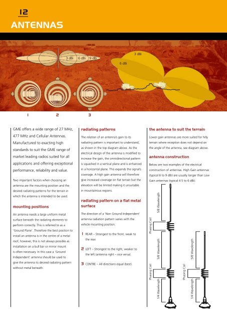
3 dBi 6 dBi 9 dBi<br />
6 dBi<br />
3 dBi<br />
1 2 3<br />
GME offers a wide <strong>range</strong> of 27 MHz,<br />
477 MHz and Cellular Antennas.<br />
Manufactured to exacting high<br />
standards to suit the GME <strong>range</strong> of<br />
market leading radios suited for all<br />
applications and offering exceptional<br />
performance, reliability and value.<br />
Two important factors when choosing an<br />
antenna are the mounting position and the<br />
desired radiating patterns for the terrain in<br />
which the antenna is intended to be used.<br />
mounting positions<br />
An antenna needs a large uniform metal<br />
surface beneath the radiating elements to<br />
perform correctly. This is referred to as a<br />
‘Ground Plane’. Therefore the best position to<br />
install an antenna is in the centre of a metal<br />
roof, however, this is not always possible as<br />
installation on a bull bar or mirror mount<br />
is often necessary. In this case a ‘Ground<br />
Independent’ antenna should be used to<br />
give the antenna its desired radiating pattern<br />
without metal beneath.<br />
radiating patterns<br />
The relation of an antenna’s gain to its<br />
radiating pattern is important to understand,<br />
as shown in the top diagram above. As the<br />
electrical design of the antenna is modified to<br />
increase the gain, the omnidirectional pattern<br />
is squashed in a vertical plane and is enhanced<br />
in a horizontal plane. This expands the signal’s<br />
coverage. A high gain antenna will therefore<br />
give increased coverage on flat terrain but the<br />
elevation will be limited making it unsuitable<br />
in mountainous regions.<br />
radiating pattern on a flat metal<br />
surface<br />
The direction of a ‘Non Ground Independent’<br />
antenna radiation pattern varies with the<br />
vehicle mounting position.<br />
1 Rear – Strongest to the front, weak to<br />
the rear.<br />
2 Left – Strongest to the right, weaker to<br />
the left (antenna right – vice versa).<br />
3 Centre – All directions equal (best).<br />
the antenna to suit the terrain<br />
Lower gain antennas are more suited for hilly<br />
terrain where reception does not depend on<br />
the angle of the antenna, see diagram above.<br />
antenna construction<br />
Below are two examples of the electrical<br />
construction of antennas. High Gain antennas<br />
(typical 6 to 9 dBi) are usually longer than Low<br />
Gain antennas (typical 4.5 to 6 dBi).<br />
Phasing Coil<br />
Phasing Coil<br />
1/4 Wavelength<br />
5/8 Wavelength<br />
5/8 Wavelength<br />
Phasing Coil<br />
1/4 Wavelength<br />
5/8 Wavelength