w23-760-4261 coilrite air suspension mercedes vito ... - Drive-Rite
w23-760-4261 coilrite air suspension mercedes vito ... - Drive-Rite
w23-760-4261 coilrite air suspension mercedes vito ... - Drive-Rite

Create successful ePaper yourself
Turn your PDF publications into a flip-book with our unique Google optimized e-Paper software.
1<br />
Unit 626 Kilshane Avenue, North West Business Park, Ballycoolin, Dublin 15, Ireland<br />
Telephone: +353 1 8612 632, Fax: +353 1 8612 647, email: sales@driveriteltd.com<br />
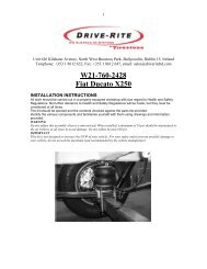
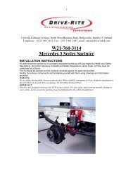
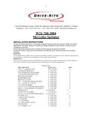
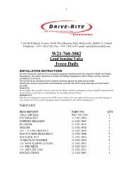
W23-<strong>760</strong>-<strong>4261</strong><br />
COILRITE AIR SUSPENSION<br />
MERCEDES VITO<br />
2004 ONWARDS REAR WHEEL DRIVE<br />
VERSION 2004 / 1<br />
INSTALLATION INSTRUCTIONS<br />
All work should be carried out in a properly equipped workshop with due regard to Health<br />
and Safety Regulations. No further reference to<br />
Health and Safety Regulations will be made, but they must be considered at all times.<br />
The kit should be opened and the contents checked against the parts list provided. Identify<br />
the various components and familiarise yourself with them using drawings and information<br />
provided.<br />
Tools required: 13 mm spanner; tube cutter; pistol drill; 8mm mm drill bit.<br />
WARNING: Do not inflate this assembly when it is unrestricted: it must be restricted by a<br />
coil spring with a textile sleeve. Do not inflate beyond the recommended operating<br />
pressure. Improper use or over inflation may cause property damage or severe personal<br />
injury.<br />
PREPARATION OF VEHICLE: It is possible to install the Coilrite <strong>air</strong>springs with the vehicle<br />
in its normal position on the road, but it may be easier if the coil springs are extended. To do<br />
this, raise the rear axle of the vehicle on a jack until the wheels are a few inches off the<br />
ground, support the body under the chassis and lower the rear axle to the ground again.
2<br />
Remove the bump stops by pulling them down to unclip from the<br />
top spigots.<br />
Decide which side of the vehicle to mount the inflation valve. The<br />
valve should be easily accessible but protected, and on the same<br />
side of the vehicle as you intend to mount the pressure gauge (if<br />
used): a suitable location for this is inside the rear of the vehicle.
3<br />
Cut a generous length of <strong>air</strong> tubing to reach from the inflation valve<br />
to the bottom of the nearest coil spring, routing it along the chassis<br />
and <strong>suspension</strong> arm, allowing sufficient slack for <strong>suspension</strong><br />
movement.<br />
Tube cutter<br />
Insert one end of this tube into the <strong>air</strong> fitting in the <strong>air</strong>spring.<br />
Enlarge the holes in the plastic plugs holding the bottom of the coil<br />
springs to allow the <strong>air</strong> tubes to pass through.<br />
Drill & 8 mm bit
4<br />
Position the bottom spacers at the bottom of the coil springs.<br />
Position the top spacers so they cover the top spigots.<br />
Feed the <strong>air</strong> tube out through the hole in the bottom of the spring,<br />
and compress the <strong>air</strong>spring to insert it into the coil spring.
5<br />
Cut another generous length of <strong>air</strong> tubing to reach from the bottom<br />
of the other coil spring to the tube coming from the first, routing it<br />
along the <strong>suspension</strong> arms so that it can be neatly held in place.<br />
Insert one end of this tube into the <strong>air</strong> fitting in the second <strong>air</strong>spring<br />
feed the tube through the hole, and insert the <strong>air</strong>spring into the coil<br />
spring, as before.<br />
Feed the tubes out up through the wishbones.<br />
Cut the tube between the inflation valve and the first spring<br />
squarely, and insert a T fitting between the 2 ends. Connect the<br />
tube from the spring on the other side of the vehicle into the T<br />
fitting.<br />
Protect the tube<br />
with the sleeving<br />
provided where<br />
there are any sharp<br />
edges.
6<br />
Drill an 8 mm (5/16”) hole and mount the inflation valve as shown,<br />
pushing the valve through the hole from behind and attaching with<br />
2 washers and a nut.<br />
Cut the <strong>air</strong> tube to length, making sure the end is cut squarely, and<br />
push the end as far as possible into the back of the inflation valve.<br />
13mm spanner<br />
Pistol drill and 8mm<br />
bit<br />
Tube cutter
7<br />
OPTION: To mount a pressure gauge inside the rear of the vehicle. Cut the <strong>air</strong> tube squarely a short distance back from the inflation valve,<br />
and insert the ends of the tubes into a Tee fitting. Cut a length of tube long enough to reach from the T fitting to the gauge. Feed the <strong>air</strong> tube<br />
up from below and connect the tube into the gauge and the Tee fitting.<br />
Attach the <strong>air</strong> tubing to the vehicle securely using nylon ties, making sure the tube is well clear of any sharp edges or sources of heat, with<br />
sufficient slack to allow <strong>suspension</strong> movement.<br />
Do not attach to brake lines. Use protective sleeves supplied as necessary.<br />
Inflate the <strong>air</strong> helper springs to 5 bar, which is the maximum recommended operating pressure and check for <strong>air</strong> leaks with soapy water.<br />
For the best ride, use only enough <strong>air</strong> pressure in the springs to level the vehicle; this amount will vary depending on the load. It is<br />
recommended to deflate and inflate in small increments to find the ideal pressure for your vehicle.<br />
Air pressure should be checked frequently and maintained between 2.5 and 5 Bar.<br />
Damage to units may occur if pressure is too low.