W21-760-3004 Mercedes Sprinter - Drive-Rite
W21-760-3004 Mercedes Sprinter - Drive-Rite
W21-760-3004 Mercedes Sprinter - Drive-Rite

You also want an ePaper? Increase the reach of your titles
YUMPU automatically turns print PDFs into web optimized ePapers that Google loves.
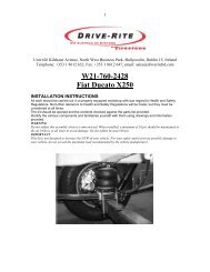
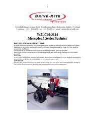
1Unit 626 Kilshane Avenue, North West Business Park, Ballycoolin, Dublin 15, IrelandTelephone: +353 1 8612 632, Fax: +353 1 8612 647, email: sales@driveriteltd.com<strong>W21</strong>-<strong>760</strong>-<strong>3004</strong><strong>Mercedes</strong> <strong>Sprinter</strong>INSTALLATION INSTRUCTIONSAll work should be carried out in a properly equipped workshop with due regard to Health and SafetyRegulations. No further reference to Health and Safety Regulations will be made, but they must beconsidered at all times.The kit should be opened and the contents checked against the parts list provided.Identify the various components and familiarise yourself with them using drawings and informationprovided.WARNINGDo not inflate this assembly when it is unrestricted. When installed, a minimum of 10 psi should be maintained inthe air bellows at all times to avoid damage. Do not inflate beyond 100 psi.IMPORTANTThis kit is not designed to increase the GVW of your vehicle. For your safety and to prevent possible damage toyour vehicle, do not exceed the maximum load recommended by the vehicle manufacturer.Parts List
Fitting Instructions <strong>W21</strong> <strong>760</strong> <strong>3004</strong>STEP 1 PREPARE THE VEHICLEYour vehicle is equipped with a rubber bump stop which ispositioned on the frame directly above the axle. Remove this bumpstop and discard. Fit the adaptor plate in place of the bump stop, slightlybending the bump stop brackets to ensure a tight fit of the adaptor plate.Bolt the top inner bracket to this adaptor plate using the trimmed M10bolts. Make sure that the slot cut out of the top inner bracket is to theinside of the chassis rail.STEP 2 INSTALL THE AIR FITTINGInstall the elbow in the air inlet hole on the top plate of the bellows.Tighten until the elbow is pointing towards the centre of the vehicle. Next,cut the air line into two equal lengths, making the cut as square to the axisof the tubing as possible. Insert the air line into the elbow and push untila positive click is felt.STEP 3 MOUNT BRACKET TO BELLOWSBefore bolting the air bellows to the lower bracket, the CSS carriage boltsshould be positioned in the bracket as illustrated. Fasten the bellows to thelower bracket using 3/8” hex bolts and spring washers provided. The topof the bellows has two studs and an air inlet hole. Position the top outerbracket on the bellows ensuring that the air inlet hole is exposed in theslot cut out of the bracket. Fasten the top outer bracket to the bellows using3/8” hex nuts and spring washers. Note, the top outer bracket with thenotch taken out of it is usually the right hand bracket (see parts list).STEP 4 INSTALL THE ASSEMBLYPlace the assembly on the axle and position so that the lower bracketrests on the axle as shown in diagram. Bolt the top outer bracket to theinner bracket (already fixed to the chassis) using the hex head carriagebolts. Position the lower bracket so that it is level on the axle and bolt inplace using the U-straps provided.STEP 5 INSTALL THE AIR LINESelect locations on the vehicle for the air inflation valves. The locationscan be on the bumper or on the body of the vehicle. Drill a 5/16” hole andinstall the air inflation valve.Run the tubing from the bellows to the valve, routing it so that it will beprotected from the direct heat of the exhaust system, and away from sharpedges. Secure the tubing in place with nylon ties. Attach the end of the airline tubing to the inflation valve.Once the inflation valves are installed, inflate the bellows to therecommended pressure and check the fittings for air leaks. If a leak isdetected at a tubing connection then check to make sure that the tube is cutas square as possible and that it is pushed completely into the fitting. If aleak is detected where the brass elbow fitting screws into the spring, thenscrew the elbow into the spring one additional turn until the leak stops.
Fitting Instructions <strong>W21</strong> <strong>760</strong> <strong>3004</strong>