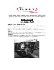
W21-760-3446 Ford Transit (Front Wheel Drive) Type 330-350
W21-760-3446 Ford Transit (Front Wheel Drive) Type 330-350
W21-760-3446 Ford Transit (Front Wheel Drive) Type 330-350
- No tags were found...

You also want an ePaper? Increase the reach of your titles
YUMPU automatically turns print PDFs into web optimized ePapers that Google loves.
Special Instructions for Air Connections1. To cut the tubing correctly an appropriate cutter must be used (not a scissors)2. When inserting the tubing into the connection, must be pushed in approximately14mm until a click is heard.3. To remove the tube, push the flange on the connection and at the same time pull thetube. (No tool is necessary.)4. ATTENTION, when a tube is removed it is important to trim 14mm from the endbefore reconnection.5. IT is advisable that LOCKTITE be used on the threaded fittings.Important• The Installation manual should be read entirely before beginning assembly.• This kit does not increase the G.V.W. (gross vehicle weight) of your vehicle, for yoursafety and to avoid any damage to your vehicle do not exceed the maximum loadingrecommended by the manufacturer.• Do not inflate air bags before assembly.• Once the kit is installed, do not exceed the max and min pressure limits, incorrect useor over inflation can cause deterioration of your suspension.PREPARATION:In order for the kit to be installed on the vehicle, it is necessary firstly to provide free spacewithin the range of the rear axle. Usually, there are no additional components which couldinterfere with installing the kits in this space. However, if components are interfering withmounting the kit, then it must be clarified whether it is still possible to mount this kit or whetherthese additional parts can be moved accordingly. You must always take care not to interferewith the vehicle parts, e.g. brake hoses, cables etc. These could be jammed or damagedwhile assembling the kit. In order to ensure this does not occur, they must be partially shifted.3
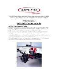
INSTALLATIONRaise the chassis from the axle to createenough room to remove the bump stops.NOTE. Do not strain any brake lines orcables.Remove the bump stop assembly. Theseholes will be used to locate the upperbrackets.Detach the ABS cables from their holder onthe left hand side of the vehicle.Take note of the thread on the bump stop asit may be a standard or fine thread.There are C/Sink Bolts provided in the kit tosuit both sizes. The correct sized bolt mustbe used.Position the upper brackets so that the foldedup part of the bracket is inside the frame andpoints up (see photo). To fix this bracket inplace use the correct M10 C/Sink bolts thathave been determined in part one. (discardthe other two M10 bolts)Position the Anti twist plates on the air bag asindicated in the photograph. Fix the lowerplates onto the air bag without tightening thescrew, to enable you to position the air bag inthe transverse direction with the slotted hole.Position the plates and air bag between theaxle and frame, checking that the side of theanti twist plate is on the outside of the frame.The Upper bracket has a slotted hole toposition the air bag in the longitudinaldirection. Screw the Air spring Nut onto theair bag without tightening it.4
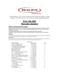
Attach the lower brackets onto the axle usingthe supports and the M10 nuts. Check thatthe alignment of the air bag is good and notin contact with another component of thevehicle. Then tighten the lower screw on theair bag and the Air spring Nut on the top nut.Screw the elbow connections onto the airbags. Then pass the ABS cable through thehigher notch in the air bag bracket.Route the longer air tube from the air springalong the underneath of the vehicle to theother side and connect with a Tee fitting tothe tube from the other air spring.Insert a length of air tube into the Tee fittingand run this tube to the location chosen forthe inflation point.Cut a long length of tubing in order to connect the valve to the nearest air bag. Do the samefor the opposite side. Choose whether you want separate inflation valves for each side or onevalve common to both sides using the T shaped connector. Use the nylon ties provided to tiethe tubing up into a safe position.Drill an 8 mm (5/16”) hole and mount theinflation valve as shown in the diagram,pushing the valve through the hole frombehind and attaching with 2 washers and anut.Cut the air tube to length, making sure theend is cut squarely, and push the end as faras possible into the back of the inflationvalve.5
OPTION:To mount a pressure gauge inside the rear of the vehicle. Cut the air tube squarely a shortdistance back from the inflation valve, and insert the ends of the tubes into a Tee fitting. Cut alength of tube long enough to reach from the T fitting to the gauge. Feed the air tube up frombelow and connect the tube into the gauge and the Tee fitting.IMPORTANT:Attach all tubing securely to the underneath of the vehicle using nylon ties.Do not attach to brake lines.Protect the tube with the sleeves provided where there are any sharp edges or sources ofheat.If the vehicle is fitted with ABS and Load Sensing Valve (LSV), then adjust the LSV to givemaximum braking (1:1).If the vehicle is fitted with ABS and no LSV, then no brake adjustment is required.For vehicles without ABS, please contact us on +353 1 8612 632Examination:After assembly, inflate air bellows and check all mounting bolts are tight. Screw allconnections tight again. It must be ensured that the mounting brackets can not move. If theplates touch the brake hose at the air bellows, then these must be moved by suitable means.After having carried out the assembly, having inflated the Airsprings andhaving checked that all the bolts as well as the pneumatic connections arequite tight. You must make sure that the mounting plates cannot move. Ifbrackets touch the brake cables towards the Airbagss, then they must bemoved with adapted means.Precautions:Never exceed the maximum and minimum recommended pressure limits.Min pressure 1barMax pressure 7barNever drive with deflated air bags.6