air suspension renault trafic electronic control version ... - Drive-Rite
air suspension renault trafic electronic control version ... - Drive-Rite
air suspension renault trafic electronic control version ... - Drive-Rite

You also want an ePaper? Increase the reach of your titles
YUMPU automatically turns print PDFs into web optimized ePapers that Google loves.
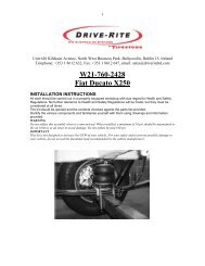
Unit 10, Parkmore Industrial Estate, Long Mile Road, Dublin 12, IrelandTelephone: +353 1 450 7833 Fax: +353 1 450 9739 email:sales@driverite.iol.ie<strong>Drive</strong>rite France SARL : 4, rue Verdun, 76410 St. Aubin les Elbeuf, FranceTél : 05.56.07.67.08 Fax : 05.56.36.89.42AIR SUSPENSIONRENAULT TRAFICELECTRONIC CONTROL VERSION (25.04.2005)INSTALLATION INSTRUCTIONSAll work should be carried out in a properly equipped workshop with due regard to Health and Safety Regulations. No further reference to Health andSafety Regulations will be made, but they must be considered at all times. It is recommended that the battery be disconnected during installation.The kit should be opened and the contents checked against the parts list provided.Identify the various components and familiarise yourself with them.Tools required : Jack or 4 post lift or other means of raising vehicle ; torque wrench ;24, 21, 19, 17, 14, 13, 10 and 8 mm spanners; screwdriver ; tube cutter ;Torx 20 & 50 ; measuring tape.
A. PREPARATIONRaise the rear of the vehicle and support itJack or 4 post liftforward of the wheels.Remove the road wheels. Wheel braceRemove the spare wheel. 17 mm spanner A special interfacespacer is requiredas supplied with thevehicle.Remove the front left-hand bracket of the sparewheel carrier.17 mm spanner Retain the bolts forreplacement later.
Allow the carrier to drop and unhook it from theright.Support the weight of the rear axle. Axle stand
Remove the shock absorber bolts, noting whichway they are located.Retain the bolts forreplacement later.
Lower the axle and remove the coil springs. JackRemove the rubber pads.
Remove the top spring plates. 13 mm spanner Retain 2 bolts fromeach side forreplacement later.
Remove the bump stop rubbers from the topspring plates.Retain the rubberbump stops.
B. INSTALLATION – SUSPENSION COMPONENTS 25/04/2005Using 3/8 UNC x 5/8” bolts , attach the <strong>air</strong>springs tothe top <strong>air</strong>spring brackets. Use the two bracketsthe opposite way up, with the more pointed endbeing the front and the side with small holes beingtowards the centre of the vehicle.14 mm spannerTighten to 25 Nm.Tighten to 25 Nm.
Screw in the ¼”npt/4 mm elbow <strong>air</strong> fittings to thetop of the <strong>air</strong>springs.14 mm spanner Use thread sealant.Identify the right-hand <strong>air</strong>spring and insert a 1470mm length of <strong>air</strong> tube covered in mm ribbedconduit into the fitting on top. Insert a 360 mmlength of tube covered in conduit into the top of theleft-hand <strong>air</strong>spring. Feed the tubes down throughthe large holes in the brackets.Cutters
Attach each <strong>air</strong>spring assembly to the correct sideof the chassis, using 2 of the original bolts andwashers each side in the original rear holes.13 mm spanner Take care not tosquash the tube.Slide the bump stop rubbers into the bump stopholders with the spacers uppermost.
Bolt on the bump stop holders through the frontholes in the top <strong>air</strong>spring brackets to the originalholes in the chassis, using M8 x 40 bolts, andspring and flat washers.13 mm spannerTorque wrenchTighten all the top<strong>air</strong>spring bracketbolts to 22 NmGently pull down the pistons and locate the recessin the piston on to the lip in the carrier.
Pass M10 x 25 socket headed bolts through theM10 spring washers, and the bottom <strong>air</strong>springplates.Allen keyUsing these, attach the bottom of each <strong>air</strong>spring tothe original spring holder.Make sure the rubber of the <strong>air</strong>spring is not twistedat all before tightening.Torque wrenchTighten to 25 Nm.
Insert the end of the tube from the left-hand<strong>air</strong>spring into one side of a T fittingPass the tube from the right-hand <strong>air</strong>springacross to the left-hand side of the vehicle insidethe chassis cross-member.
Connect it to the T fitting on the left-hand side.Take the new shock absorbers and pull down theshroud to reveal the top of the main body.
Press the button while rotating the topanticlockwise to its fullest extent. Replace theshroud.
Prime the new shock absorbers by verticallycompressing and extending them. Then, keepingthem as upright as possible, mount them on thevehicle using the original nuts and bolts in theoriginal locations.
Raise the axle to ride height using the spacerprovided in the position shown.Alternatively, if you do not have a spacer, measure240 mm between the top of the <strong>air</strong>spring and thetop rim of the lower <strong>air</strong>spring holder.
Torque the shock absorber bolts. Torque wrench Tighten to Renaultrecommendations:130NmLocate the correct groove in the underside of thefloor to the right of the handbrake adjusting bolt(see illustration P3) and insert one underfloorsupport bar as shown, pushing it in from the front ofthe chassis cross-member just behind the wheels,until the stud is almost touching the flange of thecross-member.Slide the end of the ride height sensor bracket, withthe sensor already attached, forwards in the samegroove so that the end locates on the stud of thesupport bar.
Attach the bracket to the stud using M8 flat washerand M8 nyloc nut.10 & 13 mmspannersTorque wrenchTighten to 22 NmConnect one ball joint on the <strong>control</strong> rod to the armof the ride height sensor using M5 nuts: the linkageis preset to the correct length. Connect the otherball joint to the lug on the axle inserting the nylonspacer into the overlarge hole in the lug.10 mm spannerConnect a length of <strong>air</strong> tubing protected by conduitinto the compressor, long enough to feed along thechassis to reach the left-hand <strong>air</strong>spring.
Locate the correct grooves in the underside of the flooron the right-hand side underneath the front seats (seeillustration P.3) and insert 2 rear compressor under-floorsupport bars, pushing them in from the front of thechassis cross-member, until the stop is touching theflange of the cross-member.Insert the 2 front support bars into the rear of the forwardchassis cross-member in the same way, locating thestuds through the holes, and secure with M8 nylocs andflat washers.Attach the front and rear support bars togetherusing M8 flat washers and M8 nyloc nuts on thestuds.10 & 13 mm spannersTorque wrenchTighten to 22 Nm
Attach the compressor box to the support bars using M6and M8 bolts, nylocs and flat washers.Bolt the heat shield to the compressor bracket.
3. RUNNING THE HARNESSES 25/04/2005Locate the end of the main harness which fits the height<strong>control</strong> sensor. Starting from the front of the fuel tank,feed this part of the harness over the filler neck, downthe left hand side of the chassis behind the tank andalong the stabilising bar to the ride height sensor, stayingwell clear of the exhaust. Plug the end into the heightsensor.Take the <strong>air</strong> tube from compressor down the same routeas the harness to the T fitting from the <strong>air</strong>springs at backaxle. Securely clip the harness and <strong>air</strong> tube in itsprotective conduit to the vehicle, avoiding sharp edgesand sources of heat. Coil any excess neatly and secure.
Using the 5 mm bolts supplied, attach the 2 fuse holdersand the relay at the other end of the harness to the clipplate as shown in the photo.Route the harness to the battery box and clip the plateover the end of the battery box. Secure the plate with a 6mm bolt.
Join the red wire from the compressor to the red/blackwire from the relay on the clip-plate. Join the yellow wirefrom the solenoid on the compressor to the yellow wireon the clip-plate and the blue wire from the solenoid tothe red wire on the clip-plate.Connect the white wire with the ring terminal from therear of the harness, together with the black wire from thecompressor, to the earth terminal just outside thebattery box or the negative battery terminal.Connect the 2 red wires from the fuse holders to apositive feed in the battery box.Continue the blue wire forward into the enginecompartment, and into the fuse box. Connect it to theyellow ignition <strong>control</strong> wire.Secure all wires firmly to the vehicle.
Attach the <strong>air</strong> filter to the end of a length of 6 mm tubeand mount it in the engine compartment as shown in thephoto. Feed the tube down to the compressor box,attaching it securely, and plug the tube into the inlet.Reconnect the battery and turn on the ignition. Wait forthe compressor to fill the system, them check for leaksusing soapy water.Make sure all wires and tubes are securelyfastened away from sharp edges and sourcesof heat.
4. Inflation Valve InstallationDecide which side of the vehicle to mount the inflation valve: a suitable place is in the plastic panel at the front of the rear wheel arch. The inflationvalve should be easily accessible but protected.Cut the <strong>air</strong> tube from the nearest <strong>air</strong>spring squarely 150 mm from the<strong>air</strong>spring and insert the 2 ends into a T connector. Insert a length of <strong>air</strong> tubeinto the Tee fitting and run this tube to the location chosen for the inflationpoint.Drill an 8 mm (5/16”) hole and mount the inflation valve as shown, pushingthe valve through the hole from behind and attaching with 2 washers and anut.13mm spannerPistol drill and 8mm bitCut the <strong>air</strong> tube to length, making sure the end is cut squarely, and push theend as far as possible into the back of the inflation valve.Tube cutterAttach the <strong>air</strong> tubing to the vehicle securely using nylon ties and protectiveconduit, making sure the tube is well clear of any sharp edges or sources ofheat, with sufficient slack to allow <strong>suspension</strong> movement.
USING THE INFLATION VALVEIn the event of a failure in the <strong>electronic</strong> or electrical systems <strong>control</strong>ling the <strong>air</strong> <strong>suspension</strong>, and subsequent loss of <strong>air</strong> pressure, the inflationvalve is provided solely as a safety device to enable you to continue travelling as far as a service station where the problem can be rectified.The inflation valve is usually located forward of one of the rear wheels. By using an <strong>air</strong>-line, the <strong>air</strong>springs can be re-inflated so that the vehicle is at thesame ride height as before.If you find that the <strong>suspension</strong> is still losing <strong>air</strong>, disconnect the fuses in the fuse holders on the plate clipped to the back of the battery box underneaththe vehicle.