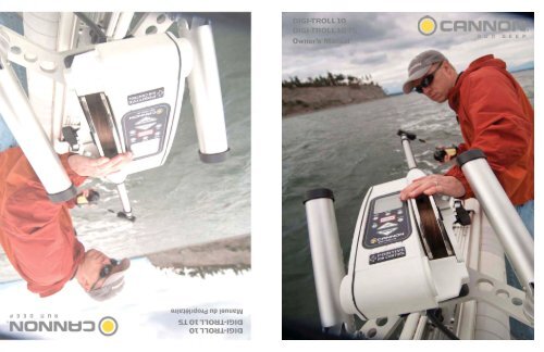
digi-troll 10 digi-troll 10 ts - Cannon Downriggers
digi-troll 10 digi-troll 10 ts - Cannon Downriggers
digi-troll 10 digi-troll 10 ts - Cannon Downriggers

You also want an ePaper? Increase the reach of your titles
YUMPU automatically turns print PDFs into web optimized ePapers that Google loves.
DIGI-TROLL <strong>10</strong><br />
DIGI-TROLL <strong>10</strong> TS<br />
Owner’s Manual
Table of Conten<strong>ts</strong><br />
TABLE OF CONTENTS<br />
Introduction ................................................................................................................................................. 3<br />
Warranty / Service Information ................................................................................................................ 4<br />
Product Overview ....................................................................................................................................... 5<br />
Installation .................................................................................................................................................... 6<br />
Mounting ...................................................................................................................................................... 6<br />
Boom and Ball Hook................................................................................................................................... 8<br />
Boom End Assembly ................................................................................................................................. <strong>10</strong><br />
Spool Cover Removal................................................................................................................................ 11<br />
Rod Holders ............................................................................................................................................... 12<br />
Cable Termination ..................................................................................................................................... 13<br />
Line Release……….....………………………………………………………………………………13<br />
Intelli<strong>troll</strong> Antenna .................................................................................................................................... 14<br />
Power Loss Crank Handle ........................................................................................................................ 15<br />
Wiring Your Downrigger ......................................................................................................................... 16<br />
Installing Transducer ................................................................................................................................ 18<br />
Getting Started ........................................................................................................................................... 19<br />
Display ........................................................................................................................................................ 20<br />
Menu ........................................................................................................................................................... 22<br />
Bottom Track ............................................................................................................................................. 22<br />
Cycle ............................................................................................................................................................ 23<br />
Up and Down ............................................................................................................................................. 24<br />
Positive Ion Control .................................................................................................................................. 24<br />
Line On Reel .............................................................................................................................................. 24<br />
Uni<strong>ts</strong> ............................................................................................................................................................ 25<br />
Un/Coated Line ......................................................................................................................................... 25<br />
Sonar Offset ................................................................................................................................................ 25<br />
Preset Programmable Depths .................................................................................................................. 26<br />
Factory Settings ......................................................................................................................................... 26<br />
Networking ................................................................................................................................................. 27<br />
Intelli<strong>troll</strong> Use ............................................................................................................................................ 27<br />
Fishing Theory ........................................................................................................................................... 28<br />
Positive Ion Control Theory ..................................................................................................................... 29<br />
Blowback Calculations .............................................................................................................................. 30<br />
Trolling Tips ............................................................................................................................................... 31<br />
Troubleshooting ......................................................................................................................................... 32<br />
Par<strong>ts</strong> Lis<strong>ts</strong> .................................................................................................................................................... 34<br />
Wiring Diagram......................................................................................................................................... 38<br />
WEEE Compliance .................................................................................................................................... 40<br />
2<br />
www.cannondownriggers.com
Introduction<br />
Overview<br />
Thank you for purchasing the <strong>Cannon</strong> Digi-Troll <strong>10</strong> electric downrigger. We have designed your new downrigger<br />
to be an accurate and reliable tool that will enhance fi shing control and improve your ability to catch<br />
fi sh.<br />
Introduction<br />
This manual covers installation and the functions of both the Digi-Troll <strong>10</strong> and Digi-Troll <strong>10</strong> TS. The Tournament<br />
Series version of the Digi-Troll is fi tted with a cast stainless steel reel, brushed fi nish stainless steel<br />
boom, and a white frame.<br />
Safety and Cautions<br />
Your <strong>Cannon</strong> downrigger should only be used for i<strong>ts</strong> intended purpose. Improper use will void the warranty<br />
and may be a safety risk.<br />
We hope that you enjoy the use of your new downrigger and enjoy the benefit of con<strong>troll</strong>ed depth<br />
fishing for years to come by always following safe boating practices and laws for wherever you are<br />
fishing.<br />
Read this manual carefully before operating your new <strong>Cannon</strong> Downrigger. Retain this manual for<br />
future reference.<br />
Warranty and Registration<br />
To receive all the benefi <strong>ts</strong> for your product warranty please fi ll out and mail the registration card. You may<br />
also register your product online at www.cannondownriggers.com.<br />
Digi-Troll <strong>10</strong><br />
Digi-Troll <strong>10</strong> TS<br />
3<br />
www.cannondownriggers.com
Product Warranty<br />
CANNON LIMITED WARRANTY<br />
................................................................................................................<br />
Johnson Outdoors Marine Electronics, Inc. warran<strong>ts</strong> to the original<br />
purchaser that if the accompanying product (see exclusions below)<br />
proves to be defective in material or workmanship within the following<br />
warranty periods, Johnson Outdoors Marine Electronics, Inc. will, at<br />
i<strong>ts</strong> option, either repair or replace same without charge (but no cash<br />
refunds will be made):<br />
1) The boom, motor, and reels, plus all composite par<strong>ts</strong>, including<br />
but not limited to frames and bases, will be free from defec<strong>ts</strong> in<br />
materials and workmanship, subject to normal wear and tear,<br />
for the original purchaser’s lifetime.<br />
2) All other items will have 1-year limited warranties from the<br />
date of original retail purchase, except THE FOLLOWING<br />
ITEMS THAT HAVE NO WARRANTY WHATSOEVER: boot<br />
covers, clothing, Dacron line, rubber bands, swivel lock pin,<br />
weigh<strong>ts</strong>, and wire cable.<br />
This limited warranty may be enforced only by the original purchaser;<br />
all subsequent purchasers acquire the product “as is”<br />
without any benefi t of this limited warranty. Repair or replacement<br />
of the product as set forth in this limited warranty shall<br />
be the original purchaser’s sole and exclusive remedy and<br />
Johnson Outdoors Marine Electronics, Inc.’ sole and exclusive<br />
liability for breach of this warranty.<br />
EXCLUSIONS<br />
This warranty does not apply in the following circumstances:<br />
• When the product has been connected, installed, combined,<br />
altered, adjusted, serviced, repaired, or handled in a manner<br />
other than according to the instructions furnished with the<br />
product<br />
• When the motor housing is opened by anyone other than <strong>Cannon</strong><br />
® Authorized service repair personnel.<br />
• ...................................................................................................<br />
When any defect, problem, loss, or damage has resulted from<br />
any accident, misuse, negligence, carelessness, or abnormal<br />
use, or from any failure to provide reasonable and necessary<br />
maintenance in accordance with the instructions of the owner’s<br />
manual<br />
LIMITATION AND EXCLUSION OF IMPLIED WARRANTIES AND<br />
CERTAIN DAMAGES<br />
................................................................................................................<br />
THERE ARE NO EXPRESS WARRANTIES OTHER THAN THESE<br />
LIMITED WARRANTIES. JOHNSON OUTDOORS MARINE ELEC-<br />
TRONICS, INC. DISCLAIMS LIABILITY FOR INCIDENTAL AND CON-<br />
SEQUENTIAL DAMAGES, AND IN NO EVENT SHALL ANY IMPLIED<br />
WARRANTIES (EXCEPT ON THE BOOM, MOTOR, REELS, AND<br />
ALL COMPOSITE PARTS), INCLUDING ANY IMPLIED WARRANTY<br />
OF MERCHANTABILITY OR FITNESS FOR PARTICULAR PUR-<br />
POSE, EXTEND BEYOND ONE YEAR FROM THE DATE OF PUR-<br />
CHASE (AND IN THE CASE OF THE BOOT COVERS, CLOTHING,<br />
DACRON LINE, RUBBER BANDS, SWIVEL LOCK PIN, WEIGHTS,<br />
AND WIRE CABLE, JOHNSON OUTDOORS MARINE ELECTRON-<br />
ICS, INC. DISCLAIMS ALL IMPLIED WARRANTIES). THIS WRITING<br />
CONSTITUTES THE ENTIRE AGREEMENT OF THE PARTIES WITH<br />
RESPECT TO THE SUBJECT MATTER HEREOF; NO WAIVER OR<br />
AMENDMENT SHALL BE VALID UNLESS IN WRITING SIGNED BY<br />
JOHNSON OUTDOORS MARINE ELECTRONICS, INC.<br />
Some states do not allow limitations on how long an implied warranty<br />
las<strong>ts</strong> or the exclusion or limitation of consequential damages, so the<br />
above limitation or exclusion may not apply to you. This warranty gives<br />
you specific legal righ<strong>ts</strong>, and you may also have other righ<strong>ts</strong> that vary<br />
from state to state.<br />
CANNON ® SERVICE POLICY<br />
AFTER THE APPLICABLE WARRANTY PERIOD<br />
After the applicable warranty period, or, if one of the above exclusions<br />
applies, <strong>Cannon</strong> produc<strong>ts</strong> will be repaired for a charge of par<strong>ts</strong><br />
plus labor. All factory repairs, after the applicable warranty period,<br />
carry a 90-Day Limited Warranty, subject to the exclusions and limitations<br />
stated above.<br />
TO ENFORCE WARRANTY OR TO OBTAIN REPAIRS AFTER<br />
WARRANTY<br />
To obtain warranty service in the U.S., the downrigger or part believed<br />
to be defective and the proof of original purchase (including the<br />
date of purchase) must be presented to a <strong>Cannon</strong> Authorized Service<br />
Center or to <strong>Cannon</strong>’s factory service center in Mankato, MN. Except<br />
as noted below, any charges incurred for service calls, transportation<br />
or shipping/freight to/from the <strong>Cannon</strong> Authorized Service Center or<br />
<strong>Cannon</strong>’s factory, labor to haul out, remove, re-install or re-rig produc<strong>ts</strong><br />
for warranty service, or any similar items are the sole and exclusive<br />
responsibility of the purchaser. <strong>Downriggers</strong> purchased ou<strong>ts</strong>ide of the<br />
U.S. (or par<strong>ts</strong> of such downriggers) must be returned prepaid with<br />
proof of purchase (including the date of purchase and serial number)<br />
to any Authorized <strong>Cannon</strong> Service Center in the country of purchase.<br />
Warranty service can be arranged by contacting a <strong>Cannon</strong> Authorized<br />
Service Center listed on the enclosed sheet, or by contacting the<br />
factory at 1-800-227-6433 or Fax 1-800-527-4464. If the necessary<br />
repairs are covered by the warranty, we will pay the return shipping<br />
charges to any destination within the United States.<br />
DO NOT return your <strong>Cannon</strong> downrigger or par<strong>ts</strong> to your retailer. Your<br />
retailer is not authorized to repair or replace them.<br />
Major par<strong>ts</strong>, such as the motor and main frame, must be returned<br />
to Johnson Outdoors Marine Electronics, Inc. in Mankato, Minnesota,<br />
or a <strong>Cannon</strong> Authorized Service Center, for repair or replacement. To<br />
reduce shipping cos<strong>ts</strong>, we suggest removal of loose par<strong>ts</strong> such as the<br />
boom and rod holders. Small par<strong>ts</strong> that can be easily removed such as<br />
the handle and/or the counter, may be removed from the downrigger<br />
and returned for repair or replacement.<br />
Retain your sales receipt! Proof of purchase must accompany<br />
product when returned.<br />
Return Address: <strong>Cannon</strong><br />
121 Power Drive<br />
Mankato, MN 56001<br />
FOR YOUR INFORMATION:<br />
_______________________Serial No.<br />
__________________Date Purchased<br />
RETAIN THIS SECTION FOR YOUR RECORDS<br />
____________Store Where Purchased<br />
4<br />
www.cannondownriggers.com
Introduction to Con<strong>troll</strong>ed Depth Fishing<br />
....................................................................................<br />
Undoubtedly there are many fi shermen familiar with<br />
the methods and use of con<strong>troll</strong>ed depth fi shing.<br />
During the mid 1960’s the state of Michigan introduced<br />
Pacifi c salmon into the Great Lakes in an attempt<br />
to revitalize i<strong>ts</strong> sport fi shing industry. From this<br />
successful transplant, new fi shing techniques and<br />
equipment were developed. One such method was<br />
con<strong>troll</strong>ed depth fi shing which enabled fi shermen to<br />
place a lure at a desired depth by utilizing downriggers.<br />
....................................................................................<br />
Because of the varying factors (water temperature,<br />
thermocline, weather, tides, time of day, or time of<br />
year) it is necessary for successful fi shing to maintain<br />
specifi c water depths that coincide with fi sh<br />
movemen<strong>ts</strong> and feeding patterns.<br />
One essential feature of the downrigger is the depth<br />
meter or gauge that indicates lure depth. This allows<br />
the angler to control as well as return to specifi c<br />
depths where fi sh have been caught.<br />
...................................................................................<br />
Due to the success of con<strong>troll</strong>ed depth fi shing,<br />
downriggers are now being used throughout the<br />
world to catch a wide variety of species in both fresh<br />
and salt water. Whether fi shing for blues off Rhode<br />
Island, walleyes in Lake Erie, sailfi sh off the coast of<br />
Florida, or stripers in Tennessee, the use of downriggers<br />
will make your fi shing more successful and<br />
more enjoyable.<br />
3<br />
Product Overview<br />
7<br />
5<br />
1<br />
2<br />
8<br />
4<br />
6<br />
Digi-Troll <strong>10</strong> TS<br />
Par<strong>ts</strong> Description<br />
1. Reel This is used to spool the cable, available in lengths ranging from 150 to 400 feet.<br />
2. Boom This is used to extend the weight out from the body of the downrigger and has a<br />
pulley fi xed to i<strong>ts</strong> end. Boom lengths range from 24 to 53 inches.<br />
3. Swivel Head This relays the cable at the end of the boom to lower the weight.<br />
4. Cable This connec<strong>ts</strong> to the weight. Cable material is 150 lb. test stainless steel cable.<br />
5. Keypad/LCD Keypad is used to control the functions of the downrigger. The LCD display<br />
provides feedback of the downrigger functions.<br />
6. Mounting Base This attaches to the boat, enabling you to place the downrigger where you<br />
choose.<br />
7. Rod Holder This holds your fi shing rods while <strong>troll</strong>ing and may also be used for storing<br />
rods.<br />
5<br />
8. Boom Clamps These lock the boom sectios together after the boom has been extended or retracted.<br />
www.cannondownriggers.com
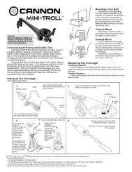
Installation<br />
Downrigger Mounting on Boa<strong>ts</strong><br />
A downrigger should be mounted wherever it is<br />
easy to operate and observe. You want to be able to<br />
see your fishing rod and to react quickly. So, choosing<br />
a good location to mount your downrigger on your<br />
boat is very important.<br />
Due to the great variety of boa<strong>ts</strong> available,<br />
mounting your downrigger can be a diffi cult decision.<br />
<strong>Cannon</strong> has a complete line of mounting and fi shing<br />
accessories to aid in your fi shing experience. Before<br />
making any permanent changes to your boat consider<br />
what accessories might be used in your application.<br />
Arrows Indicate<br />
Typical Mounting<br />
Locations<br />
Installing the Base on Your Boat<br />
Decks up to 7/16” thick<br />
Where access to the underside<br />
of the deck is not available, the mounting base can be<br />
mounted using wellnu<strong>ts</strong>. Use the base as a template<br />
to mark locations and drill four wellnut clearance holes.<br />
Mount the base using four 1/4-20 x 1-1/2” truss head<br />
screws and four wellnu<strong>ts</strong>. Tighten the screws so the<br />
wellnu<strong>ts</strong> are firmly compressed as pictured.<br />
Decks up to<br />
7/16” Thick<br />
Decks thicker than 7/16”<br />
For decks thicker than 7/16”, or<br />
where the underside of the deck is accessible, mount<br />
the base with screws, nu<strong>ts</strong>, and washers. Use the base<br />
as a template to mark the locations and drill four 9/32”<br />
holes. Use four 1/4-20 x 2” truss head screws and four<br />
each flat washers and nu<strong>ts</strong>. Fasten the base to the deck<br />
as pictured. NOTE: Wellnu<strong>ts</strong> SHOULD NOT be used<br />
on decks thicker than 7/16”.<br />
Decks Thicker<br />
Than 7/16”<br />
Thick<br />
6<br />
www.cannondownriggers.com
Decks thinner than 1/4”<br />
Use a <strong>Cannon</strong> deck plate (PN<br />
2200693) to prevent defl ection and add stability to decks<br />
thinner than 1/4”. Use the deck plate as a template to<br />
mark the hole locations.<br />
If access to the underside of<br />
the deck is not available, the deck plate can be mounted<br />
using screws and wellnu<strong>ts</strong>. Use the deck plate as a<br />
template to mark locations and drill 4 wellnut clearance<br />
holes. Use four 1/4-20 x 1-1/2” fl at head screws and four<br />
wellnu<strong>ts</strong> to mount deck plate. Tighten the screws so the<br />
wellnu<strong>ts</strong> are fi rmly compressed.<br />
Where the underside is accessible,<br />
the deck plate can be mounted using screws, nu<strong>ts</strong>,<br />
and washers. Drill 9/32” holes. Use four 1/4-20 x 1-1/2”<br />
fl at head screws, nu<strong>ts</strong> and washers (fl at and lock). Fasten<br />
plate to deck. To secure the mounting base to the<br />
deckplate use four 1/4-20 x 1” truss head screws.<br />
The Low-Profi le Swivel Base mounting follows the same<br />
procedure as for the deck plate except that four 1/4”-<br />
20 x 1-1/2” truss head screws are used to fasten the<br />
mounting base and four additional 1/4”-20 x 2” truss<br />
head screws fi x the swivel base to the boat deck.<br />
Low-Profile Swivel Base<br />
Installation<br />
NOTE: When using the telescopic boom, we strongly<br />
recommend the use of a deck plate on all boa<strong>ts</strong> to<br />
provide adequate stability for the downrigger.<br />
7<br />
www.cannondownriggers.com
Installation<br />
INSTALLING THE BOOM AND BALL HOOK<br />
1) Remove the ball hook collar, ball hook, and 1/4-20<br />
nut from the included hardware bag assembly.<br />
2) Thread the nut onto the ball hook, then thread the<br />
ball hook into the ball hook collar. Do not tighten yet<br />
(Figure 1).<br />
3) Slide ball hook collar onto the end of the boom and<br />
leave it loose. (Figure 2)<br />
4) Insert boom with ball hook collar assembly into<br />
frame (Figure 3) and line up holes in boom with holes<br />
in frame (Figure 4).<br />
FIGURE 1<br />
5) Remove 1/4-20 x 2” bolt and 1/4-20 nylon locknut<br />
from included hardware bag assembly.<br />
FIGURE 2<br />
FIGURE 3<br />
8<br />
FIGURE 4<br />
www.cannondownriggers.com
6) Insert the 1/4-20 nylon locknut into the hex pocket on<br />
the nose of the frame (motor side of frame). (Figure 5)<br />
7) Insert 1/4-20 x 2” bolt into reel side of frame nose.<br />
With a Phillips head screw driver, thread bolt into nylon<br />
locknut from step 6. Tighten bolt until the end of the bolt<br />
is fl ush with the top of the nut. (Figure 6)<br />
Installation<br />
8) Slide ball hook collar to your preferred location. Hand<br />
tighten the ball hook into boom tube. Tighten enough so<br />
that there is no movement on the boom. (Figure 7)<br />
FIGURE 5<br />
Important: Do not overtighten ball hook or permanent<br />
deformation of the boom is possible.<br />
9) Once ball hook is secure, with a 7/16” wrench, tighten<br />
the 1/4-20 nut until secure with ball hook collar.<br />
(Figure 8)<br />
**TELESCOPIC BOOM ONLY**<br />
FIGURE 6<br />
To adjust the boom length (with the boom extending<br />
away from you) rotate the clamps (See item # 8 on page<br />
5) approximately ¼ turn counter-clockwise to unlock and<br />
slide the boom section to the desired position. Once in<br />
place, lock the clamps by rotating clockwise until tight.<br />
FIGURE 7<br />
FIGURE 8<br />
9<br />
www.cannondownriggers.com
Installation<br />
BOOM END PULLEY<br />
Telescopic Boom<br />
1) Remove boom end assembly from hardware bag.<br />
2) Remove #8 self tapping screw from hardware bag.<br />
3) Insert boom end post into end of the small tube of the<br />
telescopic boom assembly. (Figure 9)<br />
4) Align hole in boom post with hole in small end tube.<br />
(Figure <strong>10</strong>)<br />
5) Secure boom end with #8 screw as shown. Tighten<br />
with Phillips head screw driver.<br />
FIGURE 9<br />
FIGURE <strong>10</strong><br />
<strong>10</strong><br />
www.cannondownriggers.com
REMOVABLE SPOOL COVER<br />
Your new downrigger comes with a removable spool<br />
cover. By removing this cover, you are able to gain<br />
easy access to your spooled cable and easy spool<br />
removal. This feature allows you to easily access<br />
tangled line, get it repaired and get you back into action<br />
quickly.<br />
Installation<br />
FIGURE 11<br />
This feature also allows you to have<br />
multiple reels for different types of line. By purchasing<br />
additional reels, you can wind each with a different<br />
type of cable (i.e. Uncoated cable, Coated Cable,<br />
Mono, etc.). This allows you to switch out desired<br />
cables quickly and easily.<br />
NOTE: Remove all tension from the line before removing<br />
or replacing the spool.<br />
Follow the below steps to remove the side cover:<br />
1) Loosen and remove the clutch knob. Turn the<br />
clutch knob clockwise until it is free of the motor shaft.<br />
(Figures 11 & 12)<br />
2) Loosen the two 1/4-20 Phillips head screws on opposite<br />
sides on the cover. (Figure 13)<br />
FIGURE 12<br />
NOTE: Screws are captured in the cover and will not<br />
come out completely.<br />
3) Remove the cover and you now have complete access<br />
to the spool. (Figures 14 & 15)<br />
4) Reassemble by reversing the above steps.<br />
Note: Take care when removing the spool over open<br />
water so that the clutch pad or clutch disk doesn’t get<br />
pulled off as well.<br />
FIGURE 13<br />
WARNING: Do not touch the cable reel while the<br />
downrigger is in use.<br />
FIGURE 14 FIGURE 15<br />
11<br />
www.cannondownriggers.com
REPLACING THE CLUTCH PAD<br />
Installation<br />
To replace the clutch pad, follow the steps for removing<br />
the spool. Once the spool is removed, you have access<br />
to the clutch pad. (Figure 16) Simply pull it off the shaft<br />
and replace. Reassemble the spool and cover in the<br />
reverse order.<br />
FIGURE 16<br />
ATTACHING THE ROD HOLDER(S)<br />
The locking rod holder(s) incorporate a locking tooth<br />
design which can be easily adjusted every 15° with the<br />
soft grip knob. The symmetrical design will allow mounting<br />
of the rod holder on either side of the downrigger or<br />
two rod holders at the same time. The unique two piece<br />
design allows independent adjustment of the rod holder<br />
and the rod holder arm in two axes.<br />
(Figure 17)<br />
Caution: This rod holder is intended for use of up to<br />
30 lb. test line only and is not recommended for use<br />
with any tackle IGFA (International Game Fish Association)<br />
rated higher than 30 lb. A safety strap (not included) is<br />
recommended for all applications.<br />
FIGURE 17<br />
NOTE: The rod holder assembly is not covered<br />
under warranty when used with tackle above 30 lbs.<br />
Equipment placed in the rod holders and the loss<br />
thereof is the responsibility of the user and is in no<br />
way warranted by Johnson Outdoors, Inc. Mounting<br />
must be in accordance with the above instructions<br />
and pictures to comply with the product warranty.<br />
To install the rod holder(s):<br />
FIGURE 18<br />
12<br />
1) Fasten rod holder to rod holder elbow using supplied<br />
spring and knob.<br />
2 ) Attach the rod holder to the downrigger on either side<br />
using the supplied spring and knob. (Figure 19)<br />
3) Repeat the above steps for the other side if (2) rod<br />
holders are to be mounted.<br />
The rod holders can be adjusted by loosening either<br />
knob until the locking teeth are free from each other.<br />
Rotate the rod holder or arm to the desired position and<br />
re-tighten knob.<br />
FIGURE 19<br />
www.cannondownriggers.com
TERMINATING THE DOWNRIGGER CABLE<br />
Installation<br />
TIP: Use only straight cable when routing thru the terminator. Worn or kinked cable can be stressed<br />
and may break prematurely when retrieving <strong>troll</strong>ing weigh<strong>ts</strong>.<br />
ATTACHING THE LINE RELEASE (UNI-RELEASE)<br />
The <strong>Cannon</strong> Uni-Release attaches directly to the downrigger<br />
weight. Attach fi shing line to the clip at the end of<br />
the release, and then click through a series of increasing<br />
tension settings. The release can be used with any<br />
test line on salt or fresh water and may be adjusted from<br />
2 to 22 pounds of grip tension on the line.<br />
To change line release tension, turn tension knob to (+)<br />
to increase or (-) to decrease. Tension also may vary<br />
according to where the line is placed in the grips. Higher<br />
tension is on the line if it is set back toward the hinge,<br />
and lower if set closer to the opening. To open the release,<br />
spread the release arms with thumb and forefi n-<br />
ger applying pressure to the sides.<br />
13<br />
www.cannondownriggers.com
Installation<br />
USING YOUR DIGI-TROLL WITH THE INTELLITROL<br />
ACCESSORY<br />
Both the Digi-Troll 5 and Digi-Troll <strong>10</strong> are compatible<br />
with the IntelliTroll accessory. The Digi-Troll 5 receives<br />
the IntelliTroll data and sends it to your Humminbird fishfinder<br />
(using the <strong>Cannon</strong>link accessory). You can also<br />
use the Intelli<strong>troll</strong> monitor and antenna cable assembly<br />
to display sensor information. The Digi-Troll <strong>10</strong> does the<br />
same thing but also displays the IntelliTroll information<br />
on the internal LCD display.<br />
To install the Intelli<strong>troll</strong> on the Digi-Troll follow the below<br />
steps:<br />
1) Locate the antenna mounting bolt in the location<br />
shown. (Figure 20)<br />
2) With a 1/4” wrench, loosen the bolt and remove.<br />
(Figure 21)<br />
3) Install the antenna spring that came with the Intelli<strong>troll</strong><br />
sensor kit. Insert bolt into the closed loop on the spring.<br />
(Figure 22)<br />
4) Tighten bolt until tight. (Figure 23)<br />
Caution: Do not over tighten as the stainless steel bolt<br />
head may shear with too much torque.<br />
5) Once the antenna is installed, run downrigger cable<br />
through center of spring. (Figures 24 & 25)<br />
Note: It is recommended that you use the coated cable<br />
that came with your Intelli<strong>troll</strong> sensor for proper sensor<br />
operation. The use of non-coated could result in<br />
poor display performance and/or a loss of data signal.<br />
Refer to your Intelli<strong>troll</strong> owners manual for more detailed<br />
instructions.<br />
FIGURE 20<br />
FIGURE 21<br />
FIGURE 22<br />
14<br />
FIGURE 23<br />
www.cannondownriggers.com
6) Terminate cable as previously described.<br />
Your Digi-Troll is now Intelli<strong>troll</strong> compatible. Once you<br />
attach your Intelli<strong>troll</strong> to the cable per the instructions<br />
included, your Digi-Troll <strong>10</strong> will display the data on it’s<br />
screen. The Digi-Troll 5 will pass this data on to the<br />
<strong>Cannon</strong>link for display on your Humminbird fi sh fi nder.<br />
Installation<br />
FIGURE 24<br />
FIGURE 25<br />
USING THE INCLUDED POWER LOSS MANUAL<br />
CRANK HANDLE<br />
In case of a dead battery, your downrigger comes<br />
equipped with a power loss manual crank handle. This<br />
handle allows for the retrieval of your weight should you<br />
lose power or have an electrical failure. To utilize the<br />
handle follow the below steps.<br />
WARNING: LOOSENING OR REMOVING THE<br />
CLUTCH KNOB WILL RELEASE THE SPOOL AND<br />
ALLOW IT TO RUN FREE. MAKE SUIRE YOU HOLD<br />
THE SPOOL BEFORE REMOVING THE CLUTCH<br />
KNOB.<br />
FIGURE 26<br />
1) Unplug downrigger and secure reel.<br />
2) Rotating clockwise, remove the clutch knob.<br />
(Figure 26)<br />
CAUTION: Take care when removing the clutch knob<br />
over open water.<br />
3) Install the handle’s hex pattern to match the hex pattern<br />
on the spool. Once installed, you can start cranking<br />
up your weight. (Figure 27)<br />
FIGURE 27<br />
15<br />
www.cannondownriggers.com
Installation<br />
Wiring Your Downrigger<br />
Your Boat’s Electrical Condition<br />
It is important to make sure that your boat is properly set up before installing your Digi-Troll with Positive<br />
Ion Control (PIC). Whenever a boat is in water, various submerged par<strong>ts</strong> interact to create weak electrical curren<strong>ts</strong>.<br />
These weak electrical curren<strong>ts</strong> must be con<strong>troll</strong>ed to extend the life of the boat’s metal par<strong>ts</strong> and ensure a good fish<br />
catching environment.<br />
Check the zinc sacrifi cial anodes on your boat and on the outboard/outdrive. If they are more than 50% dissolved<br />
they should be replaced. Any coating of slime or growth should be cleaned off. All metal par<strong>ts</strong> including the<br />
hull (if metal) must be interconnected by a grounding wire. This includes motor shaf<strong>ts</strong>, outdrives, and through hull<br />
fittings. f your boat and zinc anodes are set up correctly, the voltage on the stainless steel downrigger wire should be<br />
positive when in contact with the water.<br />
With your boat in the water and the downrigger cable deployed in the water, measure the dc voltage from the<br />
cable to a grounded metal surface of the boat touching the water. It should be 0.6-0.8VDC (fixed PIC) or it should<br />
match your Digi-Troll setting if properly wired.<br />
• The use of <strong>Cannon</strong> vinyl coated lead weigh<strong>ts</strong> is recommended.<br />
• Use the <strong>troll</strong>ing weight insulators supplied with your downrigger. This insulates your weight from the positive<br />
charge on the cable. This will also ensure that the <strong>troll</strong>ing weight will stop at water level when retrieved.<br />
• The cable on your downrigger should be replaced every 2 years. Etching of the cable can weaken it physically<br />
and electrically.<br />
• In saltwater, make sure the sacrifi cial zinc anodes are replaced when half dissolved. This ensures that the boat<br />
will run with a neutral or slightly positive charge. Clean zincs on a regular basis with a non-corrosive brush.<br />
• Always make sure the boat is properly grounded to the water. This will help ensure proper PIC voltage on the<br />
cable and that the Short Stop will function properly.<br />
1.<br />
NOTE: To ensure proper operation of your Digi-Troll, ground the battery to your boat’s electrical system’s<br />
ground. Malfunctions with the PIC, communication between uni<strong>ts</strong>, or loss of operation result from faulty<br />
grounding. Always check to see if your boat is properly grounded first.<br />
1.<br />
Electrical Specifications & Wiring Instructions<br />
The Digi-Troll is rated at 30 amps (full load), 12 vol<strong>ts</strong> DC and is protected by a 25 amp manual reset circuit<br />
breaker (located under motor housing). Be sure to measure the battery voltage of your boat.<br />
WARNING! - DO NOT RUN THIS DOWNRIGGER ON A 24 VOLT BATTERY SYSTEM. THIS WILL DAMAGE THE<br />
UNIT AND VOID YOUR WARRANTY.<br />
Connecting to the Battery:<br />
It is strongly recommended that a fuse or manual reset circuit breaker be installed at the battery on the positive<br />
lead of the power cable or that you connect the downrigger to a battery selector switch. (See Fuse and Wire Specifications)<br />
Connect the positive lead (RED) to the (+) post on your battery and the negative lead (BLACK) to the (-) post<br />
on your battery or the downrigger will not operate. Use the quick disconnect plug to remove the downrigger without<br />
touching the battery.<br />
NOTE: It is strongly recommended to power your Digi-Troll with a Deep-Cycle marine battery. Only run a Digi-Troll<br />
from a Starter battery if it is recharged by an alternator while <strong>troll</strong>ing.<br />
Tip: Control degradation of the power cables and limit corrosion by using anti-oxidant gel on all connections.<br />
16<br />
www.cannondownriggers.com
Installation<br />
Rigging and Installation Guidelines:<br />
For safety and compliance reasons, we recommend that you follow American Boat and Yacht Council (ABYC) standards when<br />
rigging your boat. Altering boat wiring should be completed by a qualified technician. The following specifications are for general<br />
guidelines only:<br />
CAUTION: These guidelines apply to general rigging to support your <strong>Cannon</strong> Downrigger. Powering multiple <strong>Downriggers</strong> or<br />
additional electrical devices from the same power circuit may impact the recommended wire gauge. If you are using wire longer<br />
than that provided with your unit, follow the chart below. If you are running more than 30 feet from the battery, we recommend that<br />
you contact a qualified marine technician.<br />
Wire Specifications:<br />
0-15 ft. (0-5 meters) <strong>10</strong> gauge<br />
15-25 ft. (5-8 meters) 8 gauge<br />
25-30 ft. (8-9 meters) 6 gauge<br />
Fuse/Breaker Specifications:<br />
30 Amp, 32 Volt, waterproof, fast blow<br />
Powering Multiple <strong>Downriggers</strong><br />
17<br />
When operating multiple Digi-Trolls, run a maximum of 2 downriggers per dedicated battery. The advanced<br />
features of the Digi-Troll can keep the unit working virtually all the time. (See below for the recommended wiring<br />
setup.)<br />
Typical Operating Time*:<br />
1 Digi-Troll per battery – 24 hours.<br />
2 Digi-Trolls per battery – <strong>10</strong> hours.<br />
*Time based on lab resul<strong>ts</strong> using a 15lb weight and Deep-Cycle batteries. Actual run time will vary.<br />
Red ( + )<br />
Black ( – )<br />
Connect Multiple<br />
Batteries in Parallel<br />
www.cannondownriggers.com<br />
Le greement et les Directives D’installation :<br />
Pour la securite et les raisons d’acquiescement, nous recommandons que vous suivez Ie Conseil d’Yacht et de Bateau america in<br />
(ABYC) les normes en truquant votre bateau . Le changement de I’installation electrique de bateau devrait etre accompli par un<br />
technicien qualifi e. Les specifications suivantes sont pour les directives generales seulement :<br />
PRUDENCE: Ces directives s’appliquent au general truquant pour soutenir votre Canon Downrigger. Le branchement de<br />
<strong>Downriggers</strong> multiple ou les artifi ces electriques supplementaires du meme circuit de pouvoir peut avoir un impact sur Ie calibre<br />
metallique recommande. Si vous utilisez Ie fi l plus long que cela fourni avec votre unite, suivez Ie graphique ci-dessous. Si vous<br />
dirigez plus de 30 pieds de la batterie, no us recommandons que vous contactez un technicien marin qualifie.<br />
Specifications Metalliques :<br />
0-15 ft. (0-5 metres) <strong>10</strong> calibre<br />
15-25 ft. (5-8 metres) 8 calibre<br />
25-30 ft. (8-9 metres) 6 calibre<br />
Specifications de Fusible/Brisant :<br />
30 Ampere, 32 vol<strong>ts</strong>, impermeables, souffl e vite
Installation<br />
Digi-Troll Transducer<br />
By purchasing the optional Digi-Troll transducer accessory (149<strong>10</strong>72), the Digi-Troll <strong>10</strong> is able to display water depth<br />
and independently bottom track.<br />
Installing the Optional Transducer<br />
Proper transducer installation is critical to the performance of your Digi-Troll’s depth tracking features. For best resul<strong>ts</strong>,<br />
follow all mounting instructions carefully.<br />
Where to Mount the Transducer<br />
Any location along the bottom edge of the transom is acceptable. The preferred mounting position is within the center<br />
1/3 of the transom excluding the area directly in line with the boat’s propeller. The transducer must be mounted where<br />
the water is smooth and free of bubbles. It may be helpful to drive your boat at a variety of speeds and observe where<br />
the water fl ows most smoothly off the transom before deciding on a mounting location. The sonar signals cannot<br />
travel through either open air or turbulent water, therefore, you must make sure that the transducer is in contact with<br />
undisturbed water at all times.<br />
If you have an aluminum boat, avoid placing the transducer behind a row of rive<strong>ts</strong>. The rive<strong>ts</strong> will cause turbulence<br />
and air bubbles. Water turbulence is minimized when the transducer face is mounted below the bottom of your boat.<br />
In certain applications for non-metallic hulled boa<strong>ts</strong>, the transducer can be positioned in the bilge with the bottom surface<br />
of the transducer as level as possible. Make sure that the transducer is submerged at least 2 inches at all times.<br />
How to Mount the Transducer<br />
To mount the transducer, you will need:<br />
A slotted screwdriver<br />
A phillips screwdriver<br />
Drill with a No. 28 or 9/64” bit<br />
3/8” wrench<br />
Silicone caulk<br />
Follow the mounting instructions supplied with your transducer mounting hardware. Attach the transducer to the<br />
bracke<strong>ts</strong> and tighten the bol<strong>ts</strong> just enough to hold it in place. Using the bracke<strong>ts</strong> as a guide, mark and drill the four<br />
mounting screw holes 1/2” to 5/8” deep, using the No. 28 or 9/64” drill.<br />
Loosely attach the transducer to the transom of your boat with the four #8 self tapping screws supplied. Adjust the<br />
bracke<strong>ts</strong> until the desired height is achieved and snug up the screws.<br />
The flat surface on the transducer should be as parallel with the water surface as possible, but tipped forward just<br />
enough to keep water pressure on the fl at surface when the boat is moving and should be 1/16” to 1/8” below the hull<br />
of the boat. Tighten up the bol<strong>ts</strong>.<br />
Remove the #8 self tapping screws one at a time and fill the hole with silicone caulk. Failure to do so may seriously<br />
damage your boat! Reinsert each screw and tighten.<br />
NOTE: On aluminum boa<strong>ts</strong> it may be necessary to use a wooden backing plate between the transom and the bracke<strong>ts</strong>.<br />
Attach a 7” piece of 1 x 6 hardwood flush with the bottom of the hull, and attach the transducer per the above<br />
instructions. Be sure to varnish the wood and silicone the screw holes thoroughly to prevent leakage and damage to<br />
your boat.<br />
18<br />
www.cannondownriggers.com
Transducer Cable Routing<br />
After mounting the transducer, route the transducer cable to your Digi-Troll. Connect the transducer cable to the<br />
transducer plug at the back of the downrigger. Be sure not to damage the cable jacket. Keep the cable away from<br />
ignition, tachometer, alternator and other electrical wiring to prevent interference. Do not cut, splice or shorten the<br />
cable. Coil the excess and secure it in place. The transducer cable NEEDS to be connected before turning the unit<br />
on.<br />
Getting Started<br />
Connector removal or cable splicing voids the product warranty.<br />
Once the transducer is mounted and connected to your Digi-Troll <strong>10</strong>, the display will show the bottom depth under<br />
SONAR DEPTH on the display.<br />
TRANSDUCER INPUT<br />
CIRCUIT BREAKER<br />
DISPLAYED SONAR DEPTH<br />
FIGURE 28<br />
GETTING STARTED<br />
POWER CABLE<br />
FIGURE 29<br />
Operating the Digi-<strong>troll</strong> <strong>10</strong><br />
The Digi-<strong>troll</strong> <strong>10</strong> offers you the most advanced features available in a downrigger.<br />
• Variable Positive Ion Control.<br />
• Large LCD <strong>digi</strong>tal display for weight depth and easy programming.<br />
• Networking operation allowing you to chain several Digi-Troll <strong>10</strong>s together for bottom following with only one<br />
transducer. (Optional transducer and interfacing cable required)<br />
• Cycling mode allows the weight to be cycled between two programmable depths.<br />
• Store fi ve pre-programmed weight depths that can be selected at the touch of a key.<br />
• AUTO-UP key to quickly raise the weight to water surface.<br />
• Bottom depth monitor mode allows your downrigger to be used as a depth fi nder (optional transducer required).<br />
• A permanent storage memory to retain all the settings.<br />
• Variable speed operation<br />
• High effi ciency motor<br />
• Compatibility with <strong>Cannon</strong>link and Humminbird fi shfinders (1<strong>10</strong>0, 900, 700, or Matrix Series).<br />
• Display of the Humminbird depth on the <strong>Cannon</strong> LCD screen (using <strong>Cannon</strong>link).<br />
19<br />
www.cannondownriggers.com
Getting Started<br />
Digi-Troll <strong>10</strong> Display<br />
When the power cord is plugged in, press the power button on the keypad to turn on the downrigger. In normal usage,<br />
the display will indicate the depth of the weight in feet.<br />
(Note: A negative depth indicates distance above the water surface).<br />
During programming of special features, the display is used to indicate various settings.<br />
Digi-<strong>troll</strong> <strong>10</strong> Keypad<br />
The Digi-<strong>troll</strong> <strong>10</strong>’s key pad has eight keys located below the display.<br />
Power<br />
The ON/OFF key functions:<br />
1) Turn the Digi-<strong>troll</strong> ON - Simply press and release.<br />
2) Turn the Digi-<strong>troll</strong> OFF - Press and hold power button for three seconds.<br />
MENU<br />
The Menu moves the display through up to eight<br />
screens for programming (see section on programming<br />
for details). After 7 seconds of inactivity on the key pad,<br />
the screen rever<strong>ts</strong> back to the weight line out display.<br />
UP<br />
During manual operation, this key raises the weight<br />
when pressed. In programming mode, the UP key<br />
increases numeric values.<br />
DOWN<br />
During manual operation, this key lowers the weight<br />
when pressed. In programming mode, the DOWN<br />
key decreases numeric values.<br />
WATER ZERO<br />
The water zero key provides a reset option for<br />
depth. When pressed and held, the line out count<br />
will reset to zero.<br />
MENU<br />
The menu key provides access to all programming<br />
submenus.<br />
RUN<br />
This key is typically used to execute a function after<br />
selected using the menu system.<br />
SELECT<br />
Use the Select key to set or display the pre-programmed<br />
weight depths when in the Depth screen.<br />
To move the weight to any of the depths indicated,<br />
press the RUN key. Another function of the Select<br />
is to step through sub-menus when you are setting<br />
certain programmable parameters.<br />
AUTO UP<br />
Press AUTO UP to raise the weight to the water<br />
zero set point at any time. AUTO UP uses the<br />
speed 5 regardless of your setting and cancels any<br />
other mode of operation (bottom following, cycling,<br />
etc.) when used.<br />
20<br />
www.cannondownriggers.com
Digi-Troll <strong>10</strong> LCD Display<br />
The icons for the Digi-Troll <strong>10</strong> display are illustrated below. Icons will illuminate as they become applicable to<br />
function settings.<br />
Backlight Feature<br />
Both the keypad and LCD use electroluminescence technology for backlighting the LCD icons and the keypad<br />
buttons. This feature makes it easier to fi sh in low light conditions with your Digi-Troll <strong>10</strong>.<br />
The backlighting will automatically illuminate upon power up of the downrigger. It will time-out after 3 hours of<br />
continuous use. To restart another 3 hour lighting cycle, press the power button briefl y without turning off the<br />
downrigger.<br />
Getting Started<br />
Daytime Use<br />
Night/Low Light Use<br />
LCD Icon Layout<br />
Programming the Digi-<strong>troll</strong> <strong>10</strong><br />
The Digi-<strong>troll</strong> <strong>10</strong> contains up to eight menus that enable you to program and customize i<strong>ts</strong> operation. Any changes<br />
made using the menu system are automatically saved in permanent memory when the downrigger is turned off.<br />
NOTE: The downrigger must be turned off with the power button for the settings to be saved.<br />
The MENU key is used to enter each of the menus starting from the default screen (referred to as the depth screen).<br />
Sub levels, if any, are entered using the Select key. Additionally, pressing the Select key when in the depth screen<br />
allows you to display, change and activate up to fi ve programmable weight depths.<br />
21<br />
www.cannondownriggers.com
Getting Started<br />
The Menu System<br />
The chart below summarizes the Digi-<strong>troll</strong> <strong>10</strong>’s menu system in the order of occurrence.<br />
While programming, the UP key is used to increase the value and the DOWN key is used to<br />
decrease the value. Remember during programming, if there is no activity on the keypad for 7 seconds, the menu<br />
rever<strong>ts</strong> back to the default depth screen.<br />
NOTE: The Cycling, Speeds, Line On Reel, and PIC menu options are NOT accessible through the downrigger when<br />
connected to <strong>Cannon</strong>link.<br />
Bottom Track<br />
The Bottom Track mode is designed to help you fish consistently<br />
near the bottom. This mode of operation requires one of the following:<br />
1) Connection to <strong>Cannon</strong>link and a compatible Humminbird fishfinder (only settable at fi shfinder).<br />
or<br />
2) Optional sonar transducer attached to your downrigger and mounted according to the instructions in this manual.<br />
In the bottom track mode, the Digi-<strong>troll</strong> <strong>10</strong> maintains the weight at a fixed distance above the bottom. In order<br />
to avoid continuous weight adjustmen<strong>ts</strong> due to minor changes in bottom depth and boat motion caused by wave action,<br />
you have the ability to adjust the responsiveness of the weight. You can also define the maximum depth that you<br />
wish the weight to go to, regardless of the bottom depth.<br />
1.<br />
Caution:<br />
In order to keep the weight from touching the bottom, make sure that the bottom is well below the band that<br />
you have selected.<br />
Bottom Track Menu<br />
From the depth screen, press the menu key once. The screen shows the user-set depth limit that the weight will travel<br />
to regardless of the bottom depth. Press the UP key to increase and DOWN key to decrease. Caution: For obvious<br />
reasons, this limit must not exceed the bottom depth and/or the length of the cable. Complete running out of the cable<br />
will result in back spooling or loss of cable.<br />
22<br />
Now press the RUN key to activate the Bottom Following feature or press Select key to adjust the distance that the<br />
weight is to remain off the bottom. The range is from +50 to -50 feet. Use the negative range to compensate for the<br />
Blowback of the weight at high <strong>troll</strong>ing speeds. Press the UP or DOWN key to increase or decrease the value and<br />
press RUN key to activate the Bottom Track or press Select key once more to adjust the sensitivity of the weight<br />
depth adjustment to minor variations in depth and/or motion of the boat due to wave action. Use UP or DOWN key to<br />
adjust. The range is 1 to 16 feet. For relatively calm water, start with a setting of 4 feet. The weight will now adjust i<strong>ts</strong><br />
depth only when the bottom depth increases by 4 feet or more. However, it will always adjust for any decrease in bottom<br />
depth regardless of this setting.<br />
www.cannondownriggers.com
Getting Started<br />
Cycling Menu<br />
From the depth screen, press the MENU key once (or once from the Bottom Track screen if the transducer is connected)<br />
to enter this menu. The fi rst screen allows you to adjust the pause time of the weight between cycling movemen<strong>ts</strong>.<br />
Press UP or DOWN to adjust. You can adjust the cycle time in steps of 1 second incremen<strong>ts</strong> from 5 to 60<br />
seconds. Press the “RUN” button to activate.<br />
Press Select to adjust the cycle depth. Down (dn) will be displayed for the down boundary. Press the UP or DOWN<br />
key to increase or decrease the down boundary. Press Select again to adjust the UP boundary. Press the UP or<br />
DOWN key to increase or decrease the up boundary.<br />
23<br />
www.cannondownriggers.com
Getting Started<br />
Up Speed Menu<br />
This menu le<strong>ts</strong> you adjust the speed of the weight in the UP direction from 1 to 5 (1 slowest, 5 fastest) at all times<br />
except during the AUTO UP operation. AUTO UP is always at speed 5.<br />
Press the MENU key three times from the depth screen or once from the cycle menu. Use UP or DOWN key to select<br />
one of the fi ve speeds.<br />
Down Speed Menu<br />
This menu le<strong>ts</strong> you adjust the speed of the weight in the DOWN direction at all times.<br />
Press the Select menu to toggle between up and down speed selection. Use UP or DOWN key to select one of five<br />
speeds.<br />
Positive Ion Control Menu<br />
This menu le<strong>ts</strong> you control the PIC level from 0.2 vdc to 1.2 vdc.<br />
Press the Menu four times from the depth screen or once from the up/down screen.<br />
Line On Reel Menu<br />
This menu le<strong>ts</strong> you set the amount of line on the reel. Incremen<strong>ts</strong> are in 50 ft. This setting is important in determining<br />
true line out.<br />
Press the Menu fi ve times from the depth screen or once from the PIC screen.<br />
24<br />
www.cannondownriggers.com
Uni<strong>ts</strong> Menu<br />
This menu le<strong>ts</strong> you switch between English and Metric uni<strong>ts</strong>.<br />
Press the Menu six times from the depth screen or once from the Line On Reel Screen<br />
Getting Started<br />
Un/Coated Menu<br />
This menu le<strong>ts</strong> you switch between <strong>Cannon</strong> coated and uncoated cable. This setting is important as well in determining<br />
accurate line out.<br />
Press the Menu seven times from the depth screen or once form the Uni<strong>ts</strong> screen.<br />
Sonar Offset Menu<br />
This menu le<strong>ts</strong> you set an offset for your sonar value. In comparison with your Humminbird or other transducer, if<br />
your Digi-Troll transducer is mounted a foot or two of difference in height you can account for that difference.<br />
Press the Menu eight times from the depth screen or once from the Un/Coated screen.<br />
Bottom Depth Display<br />
(<strong>Cannon</strong>link or Optional Transducer Required)<br />
This feature allows your downrigger to be used as a depth fi nder by continuously displaying the bottom depth. The<br />
unit needs to be hooked up to either the optional Digi-Troll transducer or a Humminbird fi shfinder (1<strong>10</strong>0, 900, 700, or<br />
Matrix Series) via the <strong>Cannon</strong>link module. If hooked up to <strong>Cannon</strong>link, the sonar display will match the fi shfinders<br />
depth. The connection to the <strong>Cannon</strong>link or transducer will need to be installed prior to power up of the downrigger.<br />
25<br />
www.cannondownriggers.com
Getting Started<br />
Using Programmable Depths<br />
The Digi-<strong>troll</strong> <strong>10</strong> allows you to program and store up to five depths for quick movement of the weight without having to<br />
manually hold the DOWN key until the desired depth is reached. When in the (default) depth screen, simply press the<br />
Select key until the required depth memory is displayed. For example, pressing the Select key three times will result<br />
in a display similar to that shown on the opposite page. Use UP or DOWN keys to change the depth if desired and<br />
press the RUN key to move the weight to that depth.<br />
Digi-Troll Factory Settings<br />
Your Digi-<strong>troll</strong> <strong>10</strong> was shipped with the following factory settings so that you can use your downrigger immediately<br />
without further programming.<br />
Depth Memory Settings:<br />
#1 25 feet<br />
#2 50 feet<br />
#3 75 feet<br />
#4 <strong>10</strong>0 feet<br />
#5 150 feet<br />
Bottom Following<br />
Maximum bottom following depth<br />
50 feet<br />
Distance of weight off bottom<br />
<strong>10</strong> feet<br />
Sensitivity 6 feet<br />
Cycling<br />
Cycle time 5 seconds<br />
Cycle depth UP 90 feet<br />
Cycle depth DOWN<br />
<strong>10</strong>0 feet<br />
Line on Reel 400 feet<br />
Up speed 3<br />
Down speed 3<br />
PIC 0.6 vdc<br />
Cable setting Uncoated<br />
Uni<strong>ts</strong> English<br />
26<br />
www.cannondownriggers.com
Networking your Digi-Trolls<br />
Up to six Digi-Troll series downriggers can be networked together. The uni<strong>ts</strong> can either be network together with the<br />
optional transducer or networked together with the <strong>Cannon</strong>link accessory. To network your downriggers you will need<br />
the Relay Cable Accessory (019634) between each downrigger you would like to link. To link using the transducer, install<br />
and hook up tranducer as described in the Transducer Cable Routing section. Once the transducer is hooked up<br />
to the fi rst downrigger, install the Relay Cable Accessory from the initial downrigger Data Out connector on the back<br />
of the downrigger to the Data In connector on the next downrigger. Repeat for all connected downrigger. To network<br />
the downriggers using <strong>Cannon</strong>link, the <strong>Cannon</strong>link cable will install to the Data In connector on the fi rst downrigger.<br />
Connect all other downriggers by connecting the Relay Cable Accessory from the Data Out to the Data In of the next<br />
downrigger. A terminator is needed on the last downrigger Data Out in order for the downriggers to properly communicate.<br />
This terminator is included in the <strong>Cannon</strong>link accessory.<br />
DATA OUT<br />
Getting Started<br />
CIRCUIT BREAKER<br />
POWER CABLE<br />
FIGURE 30<br />
DATA IN<br />
Optional Intelli<strong>troll</strong> Accessory<br />
The Digi-Troll series is compatible with the <strong>Cannon</strong> Intelli<strong>troll</strong> Speed and Temp sensor. The Intelli<strong>troll</strong> sensor gives<br />
the user the speed, temperature, and depth at the weight. With the Digi-Troll <strong>10</strong>, this information is displayed on the<br />
built in LCD display. The Digi-Troll <strong>10</strong> will automatically recognize the Intelli<strong>troll</strong> when the Intelli<strong>troll</strong> is powered up.<br />
DISPLAYED INTELLITROLL DATA<br />
FIGURE 31<br />
27<br />
www.cannondownriggers.com
Fishing Theory<br />
Fishing With Your Downrigger<br />
After programming your Digi-Troll,<br />
release some line from your rod and reel so that the lure<br />
is anywhere from 5 to <strong>10</strong>0 feet behind the boat. This is<br />
called drop back. Attach the fi shing line fi rmly into the<br />
line release. Press and hold the down key to lower the<br />
weight to the desired depth as indicated on the display<br />
or select a pre-programmed weight depth. Place the<br />
fishing rod in the rod holder and reel up the slack so that<br />
your rod has a slight bend in it. When a fi sh strikes the<br />
lure, the line will separate from the release. Then you<br />
will be free to fi ght the fi sh and bring it in on your rod<br />
and reel.<br />
Manual Descent<br />
By turning the clutch knob gently clockwise (toward<br />
the boom), you can let your <strong>troll</strong>ing weight descend as<br />
fast or as slowly as you wish. Turning the knob counterclockwise<br />
(away from the boom) stops the weight. This<br />
gives you control to let it plunge rapidly or sink slowly to<br />
a predetermined <strong>troll</strong>ing depth. With multiple downriggers,<br />
you could start all your weigh<strong>ts</strong> creeping down,<br />
one at a time, and then stop them each in turn.<br />
Note: In order to track line out, the Digi-Troll must<br />
be turned on.<br />
The Positive Ion Control System<br />
Your boat has an electrical charge<br />
around the hull in water. If a boat is properly grounded<br />
and has a proper zinc anode, that charge should be<br />
slightly positive when measured from ground to the<br />
downrigger cable. Positive Ion Control (PIC) is the use<br />
of electricity to control that charge and i<strong>ts</strong> fluctuation so<br />
that it is always maintained at a specified set voltage.<br />
The practice of setting up and maintaining<br />
a slight positive charge on fishing gear has been<br />
used by commercial fishermen for many years. This<br />
practice has enabled some fisherman to increase yield<br />
when used along with other good fishing and boating<br />
practices.<br />
<strong>Cannon</strong>’s electric downriggers offer<br />
fishermen a big advantage in being able to stabilize and<br />
control the positive charge around their boat. Because<br />
of the composite construction of the frame, <strong>Cannon</strong><br />
downriggers are insulated from your boat’s hull charge.<br />
When the stainless steel downrigger<br />
cable is lowered into the water, the natural ionization between<br />
the cable and the boat creates a positive charge<br />
of 0.7 to 0.9 vol<strong>ts</strong> in saltwater and 0.3 to 0.6 vol<strong>ts</strong> in<br />
fresh water. This natural voltage is dependent upon<br />
salinity and mineral content of the water. Your actual<br />
voltage may vary.<br />
WARNING—DO NOT TOUCH THE CABLE REEL<br />
WHILE THE DOWNRIGGER IS IN USE!<br />
The Short Stop System<br />
The Short Stop system is composed of three critical<br />
componen<strong>ts</strong>: the electronic unit, the reel conductive<br />
path, and the <strong>troll</strong>ing weight insulator.<br />
While the downrigger cable is in the water, there is<br />
a minute electrical current that fl ows between the cable<br />
and the grounded metal boat componen<strong>ts</strong> in the water.<br />
When the cable clears the water, this current fl ow will<br />
stop. The Short Stop system senses this interruption<br />
and turns off the motor. The <strong>troll</strong>ing weight insulator is<br />
used to break the cable contact to the water while the<br />
weight is still in the water. The reel conductive path allows<br />
the circuit path to be made through the structure of<br />
the downrigger.<br />
Cable Terminator<br />
Weight Insulator<br />
NOTE: It may be necessary to use two <strong>troll</strong>ing<br />
weight insulators.<br />
NOTICE: Short stop and Positive Ion<br />
Control features do not function when<br />
spooled with monofilament or super<br />
lines or if the boat is not properly<br />
grounded.<br />
28<br />
Stopping the weight at water level eliminates the<br />
cable strain caused by bouncing weigh<strong>ts</strong> or weigh<strong>ts</strong> hitting<br />
the boom end. Stopping at water level will also keep<br />
the weight from hitting the boat hull.<br />
www.cannondownriggers.com
How the Positive Ion Control System Works<br />
The PIC system uses an internal circuit<br />
that passes the voltage through the drive train of the<br />
Digi-Troll to the shaft. The shaft contac<strong>ts</strong> the cable<br />
by means of a ball bearing, spring and, lastly, a one<br />
direction button head screw. Care must be taken to<br />
ensure contact between the cable and the screw when<br />
replacing the cable. When using coated cable, 3-4 ft of<br />
coating must be striped when terminating the cable to<br />
reel. Take care in ensuring that the striped portion is in<br />
contact with the button head screw.<br />
The Positive Ion Control system applies<br />
a variable 0.2 to 1.2 vol<strong>ts</strong> on the <strong>troll</strong>ing cable at all<br />
times.<br />
Measuring the Natural Electrolysis and PIC Voltage<br />
on Your Boat<br />
A voltmeter with a scale of zero to one<br />
volt will measure the natural electrolysis. Place the<br />
ground lead of the meter on the motor or the battery<br />
ground. Place the positive lead on the stainless steel<br />
downrigger cable while it is in the water. The downrigger<br />
must be unplugged. The voltage you measure on the<br />
volt meter is your boat’s natural electrolysis voltage. Use<br />
the same set up to measure the PIC voltage; just plug in<br />
the Digi-Troll and adjust the PIC voltage desired.<br />
Using Positive Ion Control<br />
Positive Ion Control is very effective<br />
when <strong>troll</strong>ing. The zone of attraction created at the<br />
downrigger wire will attract the fi sh. It is best to use a<br />
short drop back between the downrigger release and the<br />
lure. Drop backs of <strong>10</strong> to 20 ft. are typical. A drop back<br />
of 50 to <strong>10</strong>0 ft. will entirely negate the effec<strong>ts</strong> of the PIC<br />
circuit. Fishing depths greater than 125 ft. may require a<br />
slightly higher PIC voltage. If you return to shallow water<br />
fi shing remember to turn the PIC voltage down again.<br />
The correct PIC setting for best fi shing<br />
advantage varies, depending on fi sh type and location.<br />
To fully benefi t from PIC technology, it is important that<br />
you experiment with the PIC setting to fi nd the proper<br />
voltage for the gamefi sh in the area.<br />
Maintaining Your Downrigger<br />
Periodically, lightly grease the thrust<br />
bearing and bearing race found behind the clutch knob.<br />
Replace the cable at least every two years.<br />
There are no user serviceable par<strong>ts</strong> internal to the<br />
Digi-Troll. Your warranty will be void if opened by<br />
anyone other than an authorized or factory service<br />
center. For repairs or servicing your downrigger<br />
refer to the Warranty Information section of this<br />
booklet.<br />
Positive Ion Control Theory<br />
29<br />
www.cannondownriggers.com
Blowback Calculations<br />
Blowback<br />
Simply stated, blowback is what happens<br />
to the downrigger weight when you pull it through<br />
the water behind your boat. As your speed increases,<br />
so does the horizontal distance between the weight<br />
and your downrigger. The faster you go, the farther the<br />
weight is behind you. The farther the weight is behind<br />
you, the shallower the weight is.<br />
The following char<strong>ts</strong> provide you with<br />
blowback information for three sizes of <strong>Cannon</strong> downrigger<br />
weigh<strong>ts</strong> pulled at three different speeds with no<br />
lures attached and with no current. Current drag, water<br />
salinity and the use of non-<strong>Cannon</strong> produc<strong>ts</strong> will affect<br />
your actual <strong>troll</strong>ing depth.<br />
As an example, the first chart shows that if you are <strong>troll</strong>ing<br />
at 4 MPH with an 8 pound weight and you have <strong>10</strong>0<br />
FT. of cable in the water with no current; the downrigger<br />
ball is actually at a depth of about 80 FT.<br />
Blowback Char<strong>ts</strong><br />
Actual Depth of Weight (ft.)<br />
8-Lb. Weight at 2, 4, and 6 MPH<br />
Amount of Cable in Water (ft.)<br />
2 MPH<br />
4 MPH<br />
6 MPH<br />
<strong>10</strong>-Lb. Weight at 2, 4, and 6 MPH<br />
2 MPH<br />
ActualDepth of Weight (ft.)<br />
4 MPH<br />
6 MPH<br />
Amount of Cable in Water (ft.)<br />
12-Lb. Weight at 2, 4, and 6 MPH<br />
2 MPH<br />
Actual Depth of Weight (ft.)<br />
4 MPH<br />
6 MPH<br />
30<br />
Amount of Cable in Water (ft.)<br />
www.cannondownriggers.com
Ten Good Trolling Tips<br />
1) Test your lures over the boat side before<br />
sending them down and back. Do this to make sure<br />
the lure wiggles and wobbles properly without going<br />
belly up or wandering off. Some lures can be adjusted,<br />
fi ne tuned actually, to impart maximum action. For example,<br />
a slight bend in the tail of a spoon or twist of the<br />
hook eye in the nose of a plug can make a noticeable<br />
difference in how the lure performs.<br />
Also, when running two or more lures, make sure the<br />
offerings are compatible. Lures that run out of harmony<br />
with each other are bound to tangle and that means<br />
wasted time to straighten out the mess. Testing them<br />
fi rst will avoid the problem.<br />
2) Consider different sizes, shapes, and<br />
colors of lures. No one has ever fi gured out with precision<br />
what makes a fi sh strike or snub a lure. There is<br />
no doubt, that matching the forage (minnows, crayfi sh,<br />
etc.) in color, shape, action, and size can help trigger<br />
those strikes from hungry fish. On the other hand, if fish<br />
such as bluegills, small mouth bass or Coho salmon are<br />
protecting spawning beds, they may attack whatever is<br />
threatening. So, bright colors in lures may out produce<br />
bland colors.<br />
3) Vary <strong>troll</strong>ing speeds. Goosing the engine<br />
now and then or slowing to a crawl every so often<br />
will change the action of the lures and may get fi sh to<br />
strike them.<br />
4) Vary <strong>troll</strong>ing patterns and lead lengths. The amount<br />
of line you let out often determines how deep the lure<br />
will run and, to some extent, what degree of action it will<br />
impart. For starters, consider running lures about ten<br />
feet behind downrigger weigh<strong>ts</strong>. If fl at line <strong>troll</strong>ing, put<br />
them back about fi fty feet, then experiment depending<br />
on what the fi sh do.<br />
Trolling patterns affect lure action too, that is why<br />
some anglers like to wheel a lazy S course. On turns,<br />
ou<strong>ts</strong>ide lures will speed up momentarily while inside<br />
lures hang for a moment or two. Fish may nail lures that<br />
change speeds. Also, zigzag patterns allow for more<br />
water coverage, plus it keeps lures out of propeller boil,<br />
an important consideration for browns and other wary<br />
species.<br />
5) Locate fi sh on a vertical plane. Place lures in areas<br />
where fi sh might be. Skilled fi shermen call these areas<br />
the “strike zones”. They include the edges of the<br />
week beds, structure along bottom, drop-offs, preferred<br />
temperature of the target species, and the thermocline.<br />
Remember<br />
that fi sh occupy certain areas for certain reasons<br />
(sources of food, protective cover, preferred temperatures,<br />
etc.).<br />
6) Consider special kno<strong>ts</strong> and swivels. A<br />
good ball bearing swivel will all but eliminate line twist<br />
and will aid in getting maximum performance from a<br />
lure. Many anglers add the tiny swivels to split rings already<br />
on the lure i<strong>ts</strong>elf. On the other hand, a swivel may<br />
dampen the action of a sensitive lure, such as a Rapala.<br />
Some fi sherman tie tiny improved clinch or loop kno<strong>ts</strong>.<br />
Loop kno<strong>ts</strong> in particular may enhance up and down and<br />
side to side action of lures. Any good fi shing manual will<br />
explain how to tie these and other kno<strong>ts</strong>.<br />
7) Consider releases for fl atline <strong>troll</strong>ing.<br />
A good tip is to secure a piece of downrigger cable or<br />
heavy monofi lament to the water ski hook or handle<br />
below the transom of most boa<strong>ts</strong>. To the other end of<br />
the mono or cable, add a pinch-r-release. After letting<br />
out your lure to the desire distance, put the rod in i<strong>ts</strong><br />
holder, then bend the tip and secure the fi shing line in<br />
the release.<br />
8) Add a weed guard. Having trouble with<br />
weeds hanging up lures Consider tying a three-inch<br />
piece of monofi lament a foot above the lure. Leaves,<br />
smaller weeds and other debris may catch here momentarily<br />
then fall off to the side of the lure without tangling.<br />
Weedless lures are another smart consideration. Downrigger<br />
cables are effective weed catchers when <strong>troll</strong>ing<br />
for pike, muskies, or bass in weed-infested lakes.<br />
9) Add a stinger hook. When fi sh short<br />
strike, slap at lures without becoming hooked, adding a<br />
stinger hook can solve the problem. Simply tie a treble<br />
hook to one end of a four inch piece of monofi lament<br />
and then tie the extra hook to the last gang of hooks on<br />
your lure. The stinger hook, which trails the lure, provides<br />
extra insurance.<br />
<strong>10</strong>) Keep hooks sharp. Some of the best<br />
fi shermen sharpen all hooks after every fi sh caught.<br />
Hooks get dull through both use and misuse, and probably<br />
more fi sh are lost to dull poin<strong>ts</strong> than anything else.<br />
Trolling Tips<br />
31<br />
www.cannondownriggers.com
Troubleshooting<br />
Troubleshooting<br />
PROBLEM:<br />
In the UP or AUTO-UP mode the downrigger stops<br />
periodically but the display stays on or the circuit<br />
breaker trips repeatedly.<br />
SOLUTION:<br />
• Low battery. The battery voltage at the power cord<br />
is less than 11.5 vol<strong>ts</strong> (measure with a volt meter<br />
while the downrigger is pulling up the weight).<br />
• Power cable is too long or too small in diameter.<br />
Use 8 or <strong>10</strong> gauge wire if the distance between the<br />
battery and the downrigger is greater than 6 feet.<br />
• Do not overload the downrigger. It is designed to lift<br />
up to 20 lb. weigh<strong>ts</strong> only.<br />
PROBLEM:<br />
Unit does not turn on.<br />
SOLUTION:<br />
• Check polarity on power cable.<br />
• Check circuit breaker(s)<br />
PROBLEM:<br />
Unit does not count the amount of cable retrieved<br />
correctly.<br />
SOLUTION:<br />
Verify the correct line type (Coated/Uncoated) and<br />
line on reel is set to the correct length.<br />
PROBLEM:<br />
Unit does not count the depth correctly.<br />
SOLUTION:<br />
• Current was interrupted and circuit board was reset.<br />
• Check power cable connections and try to prevent<br />
power interruption.<br />
• Retrieve the <strong>troll</strong>ing weight using UP or AUTO-UP.<br />
• Unplug the power cable for 30 seconds and then<br />
reconnect.<br />
• Reset the Zero Depth to your desired position.<br />
• Verify all magne<strong>ts</strong> are present in the spool.<br />
1.<br />
PROBLEM:<br />
Unit does not display sonar depth correctly or at all.<br />
SOLUTION:<br />
With the transducer connected, power down the<br />
downrigger, wait 30 seconds, and power on the<br />
downrigger.<br />
PROBLEM:<br />
Bottom-Following option does not work.<br />
SOLUTION:<br />
• Check cable connections with transducer or<br />
with <strong>Cannon</strong>link.<br />
• Check transducer mounting.<br />
PROBLEM:<br />
Clutch slips<br />
SOLUTION:<br />
• Retighten clutch knob. Clutch knob should be<br />
just tight enough that the clutch does not slip<br />
when downrigger is in normal use. Do not use<br />
tools of any kind to tighten the clutch, hand<br />
tightening should always be sufficient.<br />
• Check clutch disc condition by removing side<br />
cover and spool. Replace if necessary.<br />
PROBLEM:<br />
Unit does not stop at water line.<br />
SOLUTION:<br />
Using the up and down buttons, adjust the weight<br />
so it is at or a little below the water line. Use the<br />
Water Zero button to set that as the new water zero<br />
point. Note: due to cable stack this water zero point<br />
may shift up or down. It may have to be adjusted<br />
continuously depending on the amount of up and<br />
down cycles.<br />
32<br />
www.cannondownriggers.com
THIS PAGE INTENTIONALLY LEFT BLANK<br />
33<br />
www.cannondownriggers.com
Par<strong>ts</strong> List<br />
1902325 Digi-Troll <strong>10</strong><br />
34<br />
www.cannondownriggers.com
Par<strong>ts</strong> List<br />
60 3390<strong>10</strong>1 KNOB-CANNON, SOFT GRIP 90 3391732 WASHER, SEALING<br />
29 3391711 PAD, CLUTCH 59 3391955 BASE-MOUNT, DT PRO/MAG ST 89 3393113 NUT, HEX, MINI-CON-X<br />
28 3392640 PIN, DRIVESHAFT 58 3991930 ASY, MNT BASE DT/MAG(SUB) 88 33909<strong>10</strong> HANDLE-CRANK, MANUAL<br />
27 3391907 PLATE, CLUTCH SHAFT 57 90<strong>10</strong>004 HDW BEARING SWIVEL BASE 87 3393461 SCREW-1/4-20 x 2” SS, PPH<br />
26 3393480 SCREW-#<strong>10</strong>X.75”PPH HI-LO SS 56 2277001 HDW RETAINER RELEASE NUT 86 9040040 HDW BOLT 1/4-20 ROLLEDTHD HOOK<br />
25 3396902 GASKET, COVER 55 3391919 PLATE, INDEX TS 85 2200148 ASY SNAP & INSULATOR<br />
24 401966-3 MIC VENT,PTFE LU LRA MATERIAL 54 2267002 BRK PLATE SWIVEL 84 9<strong>10</strong>0620 HDW SNAP SWIVEL 4/0-37 MARLIN<br />
23 3390203 COVER, MOTOR 53 2267001 ASY PLATE BASE MACHINED 83 9<strong>10</strong>0<strong>10</strong>1 CUSHION SLEEVE TERMINATOR<br />
22 3394008 ASY PCA,DIGI-TRLL <strong>10</strong>,<strong>10</strong>TS 52 2287002 HDW SPRING RELEASE PIN 82 9<strong>10</strong>0<strong>10</strong>0 CON TERMINATOR<br />
21 3393411 SCREW-FLANGE HEX HI-LO 51 3392600 PIN - RELEASE 81 2371712 WASHER-FLAT 9/32 X 5/8 X 1/16<br />
20 3996515 MOTOR/GEAR HOUSING ASSY 50 2249001 HDW KNB RELEASE PIN 80 2263<strong>10</strong>3 NUT-1/4-20 NYLOCK SS<br />
19 3392920 STRAIN-RELIEF, HEYCO M4502 49 2998905 CNN ASY, SWIVEL BASE 79 9280713 HDW SCR 1/4 20X1 1/2 TRUSS HEA<br />
18 3993220 ASSY, POWER CABLE, RETRO(SUB) 48 33957<strong>10</strong> DECAL-PIC BLACK 78 9280720 HDW SCR 1/4 20X2 TRUSS HD PHIL<br />
17 1221491 BOOT CIRCUIT BREAKER 47 3395634 DECAL- SIDE, BLACK 77 3390005 BEARING-NYLINER, #8L5-1/2-F<br />
16 3398205 CIRCUIT BREAKER, 25 AMP 46 90<strong>10</strong>280 HDW BEARING, THRUST 76 2303412 SCREW-#6-20 X 5/8 SELF TAP<br />
15 3393426 SCREW-#6-32x3/8,TRIM’D HEX CAP 45 3391737 HDW WASHER, THRUST 75 3393124 NUT-#<strong>10</strong>-32 NYLOK 18-8 SS<br />
14 1234002 HDW INSERT SS PRESS 1/4IN(SUB) 44 3390<strong>10</strong>3 KNOB, SOFT GRIP, CLUTCH 74 3393485 SCREW-#<strong>10</strong>-24X1.75 PPHMS S<br />
13 3391223 HARNESS, RF ANTENNA 43 3394605 O-RING, KNOB 73 3392013 BOOM END, NEW<br />
35<br />
www.cannondownriggers.com<br />
1902325 Digi-Troll <strong>10</strong><br />
In the U.S.A., replacement par<strong>ts</strong> may be ordered directly from CANNON Par<strong>ts</strong> Dept., 121 Power Drive, Mankato, Minnesota 56001. Be sure to provide the MODEL and SERIAL<br />
numbers of your downrigger when ordering par<strong>ts</strong>. Please use the correct part numbers from the par<strong>ts</strong> list. Payment for any par<strong>ts</strong> ordered from the CANNON par<strong>ts</strong> department,<br />
may be by cash, personal check, Discover Card, MasterCard or VISA. To order, call 1-800-227-6433 or FAX 1-800-527-4464.<br />
12 3391221 HARNESS, TRANSDUCER 42 2071718 WASHER #<strong>10</strong> NYLON RETAINING 72 3391507 SHIM, BOOM END<br />
11 3391220 HARNESS, COMM 41 2373434 SCREW-1/4-20 X 3/4 SS PPMS 71 3392300 SHEEVE, PULLEY<br />
<strong>10</strong> 3391730 WASHER, SEAL, DATA 40 3390205 COVER, REEL 70 3392520 CASE, PULLEY<br />
9 700176 CON XCAP MINI-CON PANEL MOUNT 39 9<strong>10</strong>0070 CON LEADER SLEEVE 69 3990200 ASSY-CNN, BOOM END (SUB)<br />
8 3396603 SEAL PLATE, DT<strong>10</strong> 38 3775397 400’ CABLE 68 3397900 BALL HOOK EXTRUSION<br />
7 3394019 KEYPAD, DIGI-TROLL <strong>10</strong> 37 1459666 CERAMIC MAGNET P/N 42-B-5020 67 22<strong>10</strong>821 ASY BOOM TELESCOPIC<br />
6 33965<strong>10</strong> LENS-WINDOW MAG DTIV 36 3393418 SCREW-#<strong>10</strong>-16X.75”HI-LO SS 66 2277002 ASY HDW RELEASE UNIVERSAL<br />
5 2373450 SCREW-#8-18 X 3/8 THD* (SS) 35 3391906 PLATE, CLUTCH REEL 65 3394602 WASHER, FLAT, #8, SS<br />
4 3394702 INSERT, BASE 34 3393474 SCREW-DRIVE #14 X .75” SS 64 3392033 TUBE, DUAL AXIS RD HLDR<br />
3 3394722 INSERT, PUSH ON 33 3396020 BALL BEARING, REEL 63 3394200 ARM, DUAL AXIS-ROD HOLDER<br />
2 2263<strong>10</strong>2 NUT-HEX 1/4-20 SS 300SRS 32 3392707 SPRING, REEL 62 3991904 ASSY-CNN, ROD HOLDER<br />
1 3392524 FRAME, RAW 31 3777927 REEL, ROUGH, 3.75” OD 61 3393000 RING, RETAINING, 1/4” SHAFT<br />
3777927<br />
2373450 SCREW #8-18 x 5/8” THD (SS)<br />
3775397 400’ CABLE<br />
3391737
Par<strong>ts</strong> List<br />
1902330 Digi-Troll <strong>10</strong> TS<br />
36<br />
www.cannondownriggers.com
Par<strong>ts</strong> List<br />
29 3391711 PAD, CLUTCH 58 3392033 TUBE, DUAL AXIS RD HLDR<br />
28 3392640 PIN, DRIVESHAFT 57 3394200 ARM, DUAL AXIS-ROD HOLDER<br />
27 3391907 PLATE, CLUTCH SHAFT 56 3991904 ASSY-CNN, ROD HOLDER 84 3391732 WASHER, SEALING<br />
26 3393480 SCREW-#<strong>10</strong>X.75”PPH HI-LO SS 55 3393000 RING, RETAINING, 1/4” SHAFT 83 3393113 NUT, HEX, MINI-CON-X<br />
25 3396902 GASKET, COVER 54 3390<strong>10</strong>1 KNOB-CANNON, SOFT GRIP 83 1459666 CERAMIC MAGNET<br />
24 401966-3 MIC VENT,PTFE LU LRA MATERIAL 53 3391955 BASE-MOUNT, DT PRO/MAG ST 82 33909<strong>10</strong> HANDLE-CRANK, MANUAL<br />
23 3390204 COVER, MOTOR, TS 52 3991930 ASY, MNT BASE DT/MAG(SUB) 81 3393461 SCREW-1/4-20 x 2” SS, PPH<br />
22 3394008 ASY PCA,DIGI-TRLL <strong>10</strong>,<strong>10</strong>TS 51 90<strong>10</strong>004 HDW BEARING SWIVEL BASE 80 9040040 HDW BOLT 1/4-20 ROLLEDTHD HOOK<br />
21 3393411 SCREW-FLANGE HEX HI-LO 50 2277001 HDW RETAINER RELEASE NUT 79 2200148 ASY SNAP & INSULATOR<br />
20 3996515 MOTOR/GEAR HOUSING ASSY 49 3391919 PLATE, INDEX TS 78 9<strong>10</strong>0620 HDW SNAP SWIVEL 4/0-37 MARLIN<br />
19 3392920 STRAIN-RELIEF, HEYCO M4502 48 2267002 BRK PLATE SWIVEL 77 9<strong>10</strong>0<strong>10</strong>1 CUSHION SLEEVE TERMINATOR<br />
18 3993220 ASSY, POWER CABLE, RETRO(SUB) 47 2267001 ASY PLATE BASE MACHINED 76 9<strong>10</strong>0<strong>10</strong>0 CON TERMINATOR<br />
17 1221491 BOOT CIRCUIT BREAKER 46 2287002 HDW SPRING RELEASE PIN 75 2371712 WASHER-FLAT 9/32 X 5/8 X 1/16<br />
16 3398205 CIRCUIT BREAKER, 25 AMP 45 3392600 PIN - RELEASE 74 2263<strong>10</strong>3 NUT-1/4-20 NYLOCK SS<br />
15 3393426 SCREW-#6-32x3/8,TRIM’D HEX CAP 44 2249001 HDW KNB RELEASE PIN 73 9280713 HDW SCR 1/4 20X1 1/2 TRUSS HEA<br />
14 1234002 HDW INSERT SS PRESS 1/4IN(SUB) 43 2998905 CNN ASY, SWIVEL BASE 72 9280720 HDW SCR 1/4 20X2 TRUSS HD PHIL<br />
13 3391223 HARNESS, RF ANTENNA 42 3395711 DECAL-PIC TS 71 3390005 BEARING-NYLINER, #8L5-1/2-F<br />
12 3391221 HARNESS, TRANSDUCER 41 3395634 DECAL- SIDE, BLACK 70 2303412 SCREW-#6-20 X 5/8 SELF TAP<br />
11 3391220 HARNESS, COMM 40 90<strong>10</strong>280 HDW BEARING, THRUST 69 3393124 NUT-#<strong>10</strong>-32 NYLOK 18-8 SS<br />
37<br />
www.cannondownriggers.com<br />
1902330 Digi-Troll <strong>10</strong> TS<br />
In the U.S.A., replacement par<strong>ts</strong> may be ordered directly from CANNON Par<strong>ts</strong> Dept., 121 Power Drive, Mankato, Minnesota 56001. Be sure to provide the MODEL and SERIAL<br />
numbers of your downrigger when ordering par<strong>ts</strong>. Please use the correct part numbers from the par<strong>ts</strong> list. Payment for any par<strong>ts</strong> ordered from the CANNON par<strong>ts</strong> department,<br />
may be by cash, personal check, Discover Card, MasterCard or VISA. To order, call 1-800-227-6433 or FAX 1-800-527-4464.<br />
<strong>10</strong> 3391730 WASHER, SEAL, DATA 39 3391737 HDW WASHER, THRUST 68 3393485 SCREW-#<strong>10</strong>-24X1.75 PPHMS S<br />
9 700176 CON XCAP MINI-CON PANEL MOUNT 38 3390<strong>10</strong>3 KNOB, SOFT GRIP, CLUTCH 67 3392013 BOOM END, NEW<br />
8 3396603 SEAL PLATE, DT<strong>10</strong> 37 3394605 O-RING, KNOB 66 3391507 SHIM, BOOM END<br />
7 3394019 KEYPAD, DIGI-TROLL <strong>10</strong> 36 2071718 WASHER #<strong>10</strong> NYLON RETAINING 65 3392300 SHEEVE, PULLEY<br />
6 33965<strong>10</strong> LENS-WINDOW MAG DTIV 35 2373434 SCREW-1/4-20 X 3/4 SS PPMS 64 3392520 CASE, PULLEY<br />
5 2373450 SCREW-#8-18 X 3/8 THD* (SS) 34 3390206 COVER, REEL, TS 63 3990200 ASSY-CNN, BOOM END (SUB)<br />
4 3394702 INSERT, BASE 33 9<strong>10</strong>0070 CON LEADER SLEEVE 62 3397900 BALL HOOK EXTRUSION<br />
3 3394722 INSERT, PUSH ON 32 3775397 400’ CABLE 61 33920<strong>10</strong> ASY BOOM TELESCOPIC, SS<br />
2 2263<strong>10</strong>2 NUT-HEX 1/4-20 SS 300SRS 31 1459666 CERAMIC MAGNET P/N 42-B-5020 60 3394602 WASHER, FLAT, #8, SS<br />
1 3392525 FRAME, TS 30 3397908 REEL, ROUGH, 3.75” OD, SS 59 2200<strong>10</strong>9 SALTWATER RELEASE<br />
3777927<br />
3775397 400’ CABLE<br />
2373450 SCREW #8-18 x 5/8” THD (SS)<br />
3391737
Wiring Diagram<br />
Digi-Troll <strong>10</strong> Series Wiring Diagram<br />
38<br />
www.cannondownriggers.com
NOTES:<br />
__________________________________________<br />
__________________________________________<br />
__________________________________________<br />
__________________________________________<br />
__________________________________________<br />
__________________________________________<br />
__________________________________________<br />
__________________________________________<br />
__________________________________________<br />
__________________________________________<br />
__________________________________________<br />
__________________________________________<br />
__________________________________________<br />
__________________________________________<br />
__________________________________________<br />
__________________________________________<br />
__________________________________________<br />
__________________________________________<br />
__________________________________________<br />
__________________________________________<br />
__________________________________________<br />
__________________________________________<br />
__________________________________________<br />
__________________________________________<br />
39<br />
www.cannondownriggers.com
ENVIRONMENTAL COMPLIANCE STATEMENT:<br />
It is the intention of Johnson Outdoors Marine Electronics, Inc. to be a responsible corporate citizen, operating in compliance with known<br />
and applicable environmental regulations, and a good neighbor in the communities where we make or sell our produc<strong>ts</strong>.<br />
Form No. 3397132 Rev G ECN 33602 12/11<br />
WEEE Directive:<br />
EU Directive 2002/96/EC “Waste of Electrical and Electronic Equipment Directive (WEEE)” impac<strong>ts</strong> most distributors, sellers, and manufacturers<br />
of consumer electronics in the European Union. The WEEE Directive requires the producer of consumer electronics to take responsibility<br />
for the management of waste from their produc<strong>ts</strong> to achieve environmentally responsible disposal during the product life cycle.<br />
WEEE compliance may not be required in your location for electrical & electronic equipment (EEE), nor may it be required for EEE designed<br />
and intended as fi xed or temporary installation in transportation vehicles such as automobiles, aircraft, and boa<strong>ts</strong>. In some European Union<br />
member states, these vehicles are considered ou<strong>ts</strong>ide of the scope of the Directive, and EEE for those applications can be considered excluded<br />
from the WEEE Directive requirement.<br />
This symbol (WEEE wheelie bin) on product indicates the product must not be disposed of with other household refuse. It must be disposed<br />
of and collected for recycling and recovery of waste EEE.<br />
Johnson Outdoors Marine Electronics, Inc. will mark all EEE produc<strong>ts</strong> in accordance with the WEEE Directive. It is our goal to comply in the collection,<br />
treatment, recovery, and environmentally sound disposal of those produc<strong>ts</strong>; however, these requirement do vary within European Union<br />
member states. For more information about where you should dispose of your waste equipment for recycling and recovery and/or your European<br />
Union member state requiremen<strong>ts</strong>, please contact your dealer or distributor from which your product was purchased.<br />
To download product manuals or purchase <strong>Cannon</strong> produc<strong>ts</strong> from an authorized dealer, please visit our web page at<br />
www.cannondownriggers.com<br />
<strong>Cannon</strong><br />
Johnson Outdoors Marine Electronics, LLC.<br />
121 Power Drive, Mankato, MN 56001<br />
1-800-227-6433<br />
©20<strong>10</strong> Johnson Outdoors Marine Electronics, LLC. All righ<strong>ts</strong> reserved. Product conforms to EU EMC directive<br />
204/<strong>10</strong>8/EC and Machinery Directive 2006/42/EC.<br />
WARNING: This product contains chemical(s) known to the state of California to cause cancer and/or reproductive<br />
toxicity.<br />
Form No. 3397132 Rev G ECN 33602 12/11<br />
www.cannondownriggers.com<br />
www.cannondownriggers.com