54650-01, GS5-GS504SZ-RCA-3.0 - Balboa Direct
54650-01, GS5-GS504SZ-RCA-3.0 - Balboa Direct
54650-01, GS5-GS504SZ-RCA-3.0 - Balboa Direct

Create successful ePaper yourself
Turn your PDF publications into a flip-book with our unique Google optimized e-Paper software.
C<br />
G<br />
Basic System Features and Functions<br />
Any time you change a DIP Switch, other than A1, you must reset Persistent<br />
Memory for your new DIP Switch Settings changes to take effect. If you do<br />
not reset Persistent Memory, your system may function improperly.<br />
To reset Persistent Memory:<br />
Power down by disconnecting power source from spa.<br />
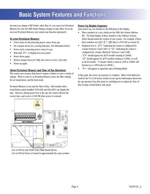
Put a jumper across J43, covering both pins. (See illustration below)<br />
Power up by connecting power source to spa.<br />
Wait until “ ” is displayed on your panel.<br />
Power down again.<br />
Remove jumper from J43 (May also move to cover 1 pin only)<br />
Power up again.<br />
About Persistent Memory and Time of Day Retention:<br />
This system uses memory that doesn’t require a battery to store a variety of<br />
settings. What we refer to as Persistent Memory stores the filter settings,<br />
the set temperature, and the heat mode.<br />
Persistent Memory is not used for Time of Day. Only models with a<br />
Serial Deluxe panel installed (VS5xxDZ and <strong>GS5</strong>xxDZ) can display the<br />
time. However, during power loss to the spa, the system will lose the<br />
correct time, and reset to 12:00 PM when power is restored.<br />
Power Up Display Sequence<br />
Upon power up, you should see the following on the display:<br />
Three numbers in a row, which are the SSID (the System Software<br />
ID). The third display of these numbers is the Software Version,<br />
which should match the version of your system. For example, if these<br />
three numbers are , that is a VS511SZ at version 38.<br />
Displayed next is: “ ” (indicating the system is configured for<br />
a heater between 3 and 6 kW) or “ ” (indicating the system is<br />
configured for a heater effectively* between 1 and 3 kW).<br />
“ ” should appear for all VS models running at 240VAC.<br />
“ ” should appear for all VS models running at 120VAC, as well<br />
as all GS models. (*A heater which is rated at 4 kW at 240VAC will<br />
function as a 1 kW heater at 120VAC.)<br />
“ ” will appear to signal the start of Priming Mode.<br />
At this point, the power up sequence is complete. Refer to the Reference<br />
Card for the VS or GS System model of your spa for information about how<br />
the spa operates from this point on, including how to adjust the Time of<br />
Day if using a Serial Deluxe style panel.<br />
J43<br />
E.GND<br />
K6<br />
G C<br />
F4 FUSE .3A 250V<br />
J23<br />
K1<br />
W1<br />
SWITCHBANK<br />
T1A<br />
K3<br />
K2<br />
F2<br />
W4<br />
E.GND<br />
J50<br />
G C<br />
J6<br />
G C<br />
SWITCHBANK A<br />
F7<br />
J17/26<br />
S1 TST<br />
S1<br />
W7<br />
FUSE 20A 250V<br />
K8<br />
K9<br />
J43<br />
J46<br />
J60 J22<br />
J6 J7 J8<br />
TST<br />
EXT.<br />
RLY<br />
J2<br />
AUX. F<br />
J1<br />
SEN. A<br />
J47<br />
G C<br />
W2<br />
W3<br />
J1A<br />
J2A<br />
SEN. B<br />
U4<br />
J29<br />
G C<br />
J13<br />
BALBOA INSTRUMENTS, INC. 2-SPD<br />
J44 VS500Z<br />
EXT RLY<br />
P/N 22972 REV D<br />
VAC<br />
MADE IN U.S.A<br />
COPYRIGHT 2005<br />
J43 on VS5xxZ and VS300 Series Main Board Shown.<br />
J43 on <strong>GS5</strong>xxZ Series is located in approximately the same position.<br />
K5<br />
1 2 3<br />
J12<br />
J20<br />
F1<br />
J10<br />
FUSE 3A 250V<br />
J18<br />
J26<br />
J90<br />
J50<br />
LINE<br />
BLK AC<br />
W1<br />
K4<br />
K1<br />
VS100<br />
P/N 22964_B MADE IN U.S.A.<br />
© 2006<br />
PUMP<br />
T0.25A 250V<br />
<strong>Balboa</strong><br />
J58<br />
G C<br />
J23<br />
NEUTRAL<br />
F2<br />
J57<br />
HEATER<br />
OZONE<br />
J29<br />
G C<br />
WHT AC<br />
K3<br />
J9<br />
TST<br />
K2<br />
K5<br />
SWITCHBANK A<br />
F4<br />
J6 J43<br />
S1<br />
TST<br />
SWITCHBANK A<br />
RST<br />
J43 on VS100/GS100 Series Main Board Shown.<br />
J6<br />
J43<br />
RST<br />
F5, F3A 250V<br />
J13 J12<br />
J7<br />
SEN. A<br />
J8<br />
SEN. B<br />
J18<br />
U4<br />
G<br />
J20<br />
C<br />
J1<br />
Page 4<br />
<strong>54650</strong>-<strong>01</strong>_A