54650-01, GS5-GS504SZ-RCA-3.0 - Balboa Direct
54650-01, GS5-GS504SZ-RCA-3.0 - Balboa Direct
54650-01, GS5-GS504SZ-RCA-3.0 - Balboa Direct

Create successful ePaper yourself
Turn your PDF publications into a flip-book with our unique Google optimized e-Paper software.
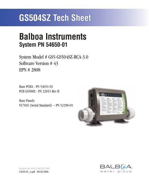
<strong>GS5</strong>04SZ Tech Sheet<br />
<strong>Balboa</strong> Instruments<br />
System PN <strong>54650</strong>-<strong>01</strong><br />
System Model # <strong>GS5</strong>-<strong>GS5</strong>04SZ-<strong>RCA</strong>-<strong>3.0</strong><br />
Software Version # 43<br />
EPN # 2808<br />
Base PCBA - PN 54651-<strong>01</strong><br />
PCB <strong>GS5</strong>00Z - PN 22<strong>01</strong>5 Rev B<br />
Base Panels<br />
VL7<strong>01</strong>S (Serial Standard) – PN 52298-<strong>01</strong><br />
Template used: 40599_N.pdf 05/07/2008<br />
<strong>54650</strong>-<strong>01</strong>_A.pdf 08/26/2008<br />
Page 1<br />
<strong>54650</strong>-<strong>01</strong>_A
System Revision History<br />
System PN EPN Date Requested By Changes Made<br />
<strong>54650</strong>-<strong>01</strong> 2808 08.26.2008 <strong>Balboa</strong> Software update to version 43<br />
Page 2<br />
<strong>54650</strong>-<strong>01</strong>_A
Basic System Features and Functions<br />
Power Requirements<br />
<br />
<br />
<br />
<br />
Requires PCB Rev B.<br />
<br />
<br />
System Outputs<br />
Setup 1 (As Manufactured)<br />
<br />
<br />
<br />
<br />
(Stereo)<br />
<br />
Optional Devices<br />
<br />
<br />
<br />
Additional Options<br />
<br />
<br />
<br />
<br />
<br />
<br />
<br />
<br />
<br />
J1<br />
J2<br />
J10<br />
J1A<br />
J2A<br />
U4<br />
J71<br />
J19<br />
J18<br />
1<br />
J60<br />
J7 J8<br />
1 1<br />
1<br />
1<br />
J44<br />
1<br />
J12<br />
Page 3<br />
J22<br />
EXT RLY AUX F SEN A SEN B VAC<br />
J11<br />
1<br />
<strong>54650</strong>-<strong>01</strong>_A
C<br />
G<br />
Basic System Features and Functions<br />
Any time you change a DIP Switch, other than A1, you must reset Persistent<br />
Memory for your new DIP Switch Settings changes to take effect. If you do<br />
not reset Persistent Memory, your system may function improperly.<br />
To reset Persistent Memory:<br />
Power down by disconnecting power source from spa.<br />
Put a jumper across J43, covering both pins. (See illustration below)<br />
Power up by connecting power source to spa.<br />
Wait until “ ” is displayed on your panel.<br />
Power down again.<br />
Remove jumper from J43 (May also move to cover 1 pin only)<br />
Power up again.<br />
About Persistent Memory and Time of Day Retention:<br />
This system uses memory that doesn’t require a battery to store a variety of<br />
settings. What we refer to as Persistent Memory stores the filter settings,<br />
the set temperature, and the heat mode.<br />
Persistent Memory is not used for Time of Day. Only models with a<br />
Serial Deluxe panel installed (VS5xxDZ and <strong>GS5</strong>xxDZ) can display the<br />
time. However, during power loss to the spa, the system will lose the<br />
correct time, and reset to 12:00 PM when power is restored.<br />
Power Up Display Sequence<br />
Upon power up, you should see the following on the display:<br />
Three numbers in a row, which are the SSID (the System Software<br />
ID). The third display of these numbers is the Software Version,<br />
which should match the version of your system. For example, if these<br />
three numbers are , that is a VS511SZ at version 38.<br />
Displayed next is: “ ” (indicating the system is configured for<br />
a heater between 3 and 6 kW) or “ ” (indicating the system is<br />
configured for a heater effectively* between 1 and 3 kW).<br />
“ ” should appear for all VS models running at 240VAC.<br />
“ ” should appear for all VS models running at 120VAC, as well<br />
as all GS models. (*A heater which is rated at 4 kW at 240VAC will<br />
function as a 1 kW heater at 120VAC.)<br />
“ ” will appear to signal the start of Priming Mode.<br />
At this point, the power up sequence is complete. Refer to the Reference<br />
Card for the VS or GS System model of your spa for information about how<br />
the spa operates from this point on, including how to adjust the Time of<br />
Day if using a Serial Deluxe style panel.<br />
J43<br />
E.GND<br />
K6<br />
G C<br />
F4 FUSE .3A 250V<br />
J23<br />
K1<br />
W1<br />
SWITCHBANK<br />
T1A<br />
K3<br />
K2<br />
F2<br />
W4<br />
E.GND<br />
J50<br />
G C<br />
J6<br />
G C<br />
SWITCHBANK A<br />
F7<br />
J17/26<br />
S1 TST<br />
S1<br />
W7<br />
FUSE 20A 250V<br />
K8<br />
K9<br />
J43<br />
J46<br />
J60 J22<br />
J6 J7 J8<br />
TST<br />
EXT.<br />
RLY<br />
J2<br />
AUX. F<br />
J1<br />
SEN. A<br />
J47<br />
G C<br />
W2<br />
W3<br />
J1A<br />
J2A<br />
SEN. B<br />
U4<br />
J29<br />
G C<br />
J13<br />
BALBOA INSTRUMENTS, INC. 2-SPD<br />
J44 VS500Z<br />
EXT RLY<br />
P/N 22972 REV D<br />
VAC<br />
MADE IN U.S.A<br />
COPYRIGHT 2005<br />
J43 on VS5xxZ and VS300 Series Main Board Shown.<br />
J43 on <strong>GS5</strong>xxZ Series is located in approximately the same position.<br />
K5<br />
1 2 3<br />
J12<br />
J20<br />
F1<br />
J10<br />
FUSE 3A 250V<br />
J18<br />
J26<br />
J90<br />
J50<br />
LINE<br />
BLK AC<br />
W1<br />
K4<br />
K1<br />
VS100<br />
P/N 22964_B MADE IN U.S.A.<br />
© 2006<br />
PUMP<br />
T0.25A 250V<br />
<strong>Balboa</strong><br />
J58<br />
G C<br />
J23<br />
NEUTRAL<br />
F2<br />
J57<br />
HEATER<br />
OZONE<br />
J29<br />
G C<br />
WHT AC<br />
K3<br />
J9<br />
TST<br />
K2<br />
K5<br />
SWITCHBANK A<br />
F4<br />
J6 J43<br />
S1<br />
TST<br />
SWITCHBANK A<br />
RST<br />
J43 on VS100/GS100 Series Main Board Shown.<br />
J6<br />
J43<br />
RST<br />
F5, F3A 250V<br />
J13 J12<br />
J7<br />
SEN. A<br />
J8<br />
SEN. B<br />
J18<br />
U4<br />
G<br />
J20<br />
C<br />
J1<br />
Page 4<br />
<strong>54650</strong>-<strong>01</strong>_A
Wiring Configuration and DIP Settings<br />
Setup 1 (As Manufactured)<br />
<br />
<br />
<br />
<br />
<br />
<br />
<br />
<br />
(Stereo)<br />
<br />
<br />
<br />
<br />
HIPot Testing Note:<br />
Disconnect slip terminal with green<br />
wires from J90 prior to performing<br />
HiPot test. Failure to disconnect may<br />
cause a false failure of the test.<br />
Reconnect terminal to J90 after<br />
successful completion of HiPot test.<br />
J52<br />
J51<br />
F6, T30A 480V<br />
J25<br />
J32<br />
1<br />
TB1<br />
J50<br />
J47<br />
AV<br />
Audio G N Visual<br />
CIRC. PUMP<br />
Circ G N Pump<br />
F4, T0.2A 250V<br />
J29<br />
OZONE PUMP 1<br />
Ozone<br />
G N<br />
J58<br />
J23<br />
2-Spd 1-Spd P1<br />
G N<br />
K9<br />
T1<br />
K6<br />
K1<br />
1-Spd P2<br />
G N<br />
J17/26<br />
OPT. BLWR/PUMP 2<br />
J46<br />
K8<br />
10VAC<br />
J72<br />
F7<br />
F10A 250V<br />
K5<br />
C9<br />
F3A 250V<br />
J20<br />
Spa<br />
G N<br />
Light<br />
F3<br />
J71<br />
10VAC<br />
F1<br />
J13<br />
2<br />
3<br />
J28<br />
W2<br />
J1<br />
J2<br />
J26<br />
J1A<br />
J2A<br />
K3<br />
J57<br />
4<br />
<strong>Balboa</strong><br />
BALBOA INSTRUMENTS, INC.<br />
<strong>GS5</strong>00Z<br />
COPYRIGHT 2007<br />
MADE IN U.S.A.<br />
P/N 22<strong>01</strong>5_B<br />
Pb<br />
W1<br />
Heater rated @ 240V<br />
J11 must be Jumpered<br />
HTR2 J1<strong>01</strong> HTR1 00<br />
<strong>3.0</strong> kW<br />
K4<br />
K2<br />
J90<br />
F2<br />
E.GND<br />
S1<br />
SWITCHBANK A<br />
J43<br />
J6<br />
TST<br />
J10<br />
J60<br />
EXT RLY<br />
J7<br />
J8<br />
1 1<br />
1<br />
1<br />
J22<br />
AUX F<br />
SEN A<br />
SEN B<br />
U4<br />
J19<br />
J12<br />
J44<br />
1<br />
1<br />
VAC J11<br />
<strong>3.0</strong>kW<br />
1<br />
J18<br />
<strong>GS5</strong>xxSZ mode<br />
WARNING: Main Power to system should be turned OFF BEFORE adjusting DIP switches.<br />
WARNING: Persistent Memory (J43) must be RESET to allow new DIP switch settings to take effect. (See Persistent Memory page)<br />
SSID #<br />
100<br />
93<br />
43<br />
<strong>3.0</strong>kW<br />
Heater<br />
J11<br />
J12<br />
A1, Test Mode OFF<br />
A2, See Table 1<br />
A6, 50 Hz<br />
A7, Exp Board Equip Disabled<br />
1<br />
A3, J17/26 Pump Disabled Enabled A8, Degrees C<br />
A9, Circ Pump OFF<br />
A5, N/A when A9 is OFF<br />
Panel Button Assignments<br />
A10, See Table 1<br />
Panel Button Positions<br />
1=Mode<br />
5=Pump 1<br />
4 1 2<br />
2<br />
2=Temp Up<br />
6=J17/26 6=Pump 2<br />
3=Temp Down<br />
5 6 7<br />
3 1 3<br />
7=Unused<br />
4=Light<br />
Page 5<br />
3<br />
2<br />
J43<br />
Memory<br />
Reset<br />
7<br />
5<br />
4<br />
6<br />
Wiring Color Key<br />
Neutral (Common) AC Connections<br />
Special AC Connections<br />
Line AC Connections<br />
10 Volt Connections<br />
Relay Control Wires<br />
Board Connector Key<br />
1 Typically Line voltage<br />
2 Typically Line voltage for 2-speed pumps<br />
3 Neutral (Common)<br />
4 Ground<br />
Note flat sides in connector<br />
<strong>54650</strong>-<strong>01</strong>_A
DIP Switches and Jumpers Definitions<br />
SSID 100 93 43<br />
DIP Switch Key<br />
A1 Test Mode (normally OFF)<br />
A2+A10 Control amp draw requirements (See Table 1)<br />
A3 “ON” position: J17/26 Enabled for 1-speed Pump only.<br />
“OFF” position: J17/26 Disabled.<br />
A4 Aux Freeze (must be OFF)<br />
A5+A9 Pump 1 speeds and Circ Modes:<br />
A5 A9 Circ Mode Pump 1 Speed<br />
OFF OFF Non-circ 2-speed<br />
ON OFF Circ "acts like Pump 1 low" (filters/polls/ect) 1-speed<br />
OFF ON 24 hours with 3°F shut-off 1-speed<br />
ON ON 24 hours with 3°F shut-off 2-speed<br />
Base Model <strong>GS5</strong>03SZ-<strong>GS5</strong>04SZ-<strong>GS5</strong>14SZ<br />
Table 1 # of Hi-Speed<br />
Pumps/Blower<br />
Before Heat Disabled<br />
A2 A10<br />
OFF OFF 0<br />
ON OFF 1<br />
OFF ON 2<br />
ON ON 3<br />
A6 “ON” position: 50Hz operation<br />
“OFF” position: 60Hz operation<br />
A7 “ON” position: Expander Board Enabled for Blower or 1-speed Pump.<br />
“OFF” position: Expander Board Disabled<br />
A8 “ON” position: temperature is displayed in degrees Celsius<br />
“OFF” position: temperature is displayed in degrees Fahrenheit<br />
When using a Blower, use X-B CE expander board. When using a 1-speed Pump 3, use X-P CE or X-P231 CE, depending on amperage requirements.<br />
* Panel with button layout is not compatible.<br />
Jumper Key<br />
J11 If using 3kW or higher wattage heater, jumper can be set in either position, but may perform better on Pins 1 and 2.<br />
If using 2.5kW or lower wattage heater, jumper must be set on 1 Pin only.<br />
J12 Factory set. DO NOT MOVE.<br />
Jumper must be on Pins 1 and 2 for <strong>GS5</strong>1xZ/<strong>GS5</strong>2xZ/<strong>GS5</strong>xxSZ/<strong>GS5</strong>xxDZ software.<br />
Jumper must be on Pins 2 and 3 for <strong>GS5</strong>0xZ software.<br />
J43 When jumper is placed on 2 pins during power-up, system will reset persistent memory.<br />
Leave on 1 pin only to enable persistent memory feature.<br />
WARNING:<br />
Setting DIP switches incorrectly may cause abnormal system behavior and/or damage to system components.<br />
Refer to Switchbank illustration on Wiring Configuration page for correct settings for this system.<br />
Contact <strong>Balboa</strong> if you require additional configuration pages added to this tech sheet.<br />
Panel Button Positions<br />
Aux Panel Information<br />
4<br />
1 2<br />
2<br />
7<br />
4<br />
Supports 2-button aux panel<br />
5 6 7<br />
3<br />
1<br />
3<br />
5<br />
6<br />
VX20<br />
5<br />
6<br />
When A3 is ON<br />
VX20<br />
5 7<br />
When A3 is OFF<br />
1=Mode<br />
2=Temp Up<br />
3=Temp Down<br />
4=Light<br />
Panel Button Assignments<br />
5=Pump 1<br />
6=Pump 2 (when A3 is ON)<br />
7=Exp Board (when A7 is ON)<br />
Supports 4-button aux panel<br />
VX40S<br />
5 6 4 7<br />
Page 6<br />
<strong>54650</strong>-<strong>01</strong>_A
AS MANUFACTURED<br />
L1<br />
N1<br />
Electrical Service Configuration Options<br />
Systems with PCB Rev B Only<br />
AV<br />
F7<br />
F1<br />
J13<br />
J50<br />
J29<br />
J23<br />
K6 K1<br />
OZONE PUMP 1<br />
K9<br />
F10A 250V<br />
J52 J51<br />
F6, T30A 480V<br />
F3A 250V<br />
G N<br />
J46<br />
CIRC. PUMP<br />
K8<br />
K5 J20<br />
J25<br />
G N<br />
C9<br />
G N<br />
J32<br />
(1 x 16 Amp or 1 x 32 Amp)<br />
F3<br />
TB1<br />
10VAC<br />
J17/26 J72<br />
1<br />
3 Wires (1 Line + 1 Neutral + 1 Protective Earth)<br />
F4, T0.2A 250V<br />
OPT. BLWR/PUMP 2<br />
J71<br />
T1<br />
J58<br />
2<br />
3<br />
4<br />
J57<br />
<strong>Balboa</strong><br />
BALBOA INSTRUMENTS, INC.<br />
<strong>GS5</strong>00Z<br />
COPYRIGHT 2007<br />
Pb<br />
MADE IN U.S.A.<br />
P/N 22<strong>01</strong>5_B<br />
W1<br />
J47<br />
J28<br />
J26<br />
G N<br />
HTR2 J1<strong>01</strong> HTR1 00<br />
W2<br />
G N<br />
K3<br />
K4<br />
K2<br />
J90<br />
Single Service, TN and TT Electrical Systems<br />
J1A<br />
J1<br />
This option is configured J2 and shipped as the default.<br />
E.GND<br />
G N<br />
Protective Earth wire (Green/Yellow) must be connected<br />
to system ground terminal as marked.<br />
J2A<br />
All equipment (pumps, blower, and heater) runs on<br />
1<br />
J18<br />
service line L1. J43 J10<br />
F2<br />
J19<br />
S1<br />
Systems using only 1 DIP switch (A10) J12 for heat disable:<br />
J60<br />
J7 J8 J44<br />
J6<br />
1 1<br />
1<br />
1 1<br />
For 1 x 16 Amp Service:<br />
TST<br />
1<br />
SWITCHBANK A<br />
EXT RLY AUX F SEN A SEN B VAC J11<br />
DIP Switch A10 must be ON.<br />
J22<br />
For 1 x 32 Amp Service:<br />
Set DIP Switch A10 such that total system amperage<br />
draw never exceeds rated service input.<br />
Systems using multiple DIP switches for heat disable:<br />
Refer to system Hot Sheet DIP Switch Definition page<br />
and set the switches shown in Table 1 such that total<br />
system amperage draw never exceeds rated service input.<br />
U4<br />
10VAC<br />
OPTIONAL<br />
L2<br />
N2<br />
L1<br />
N1<br />
J52<br />
J51<br />
F6, T30A 480V<br />
J57<br />
J25<br />
J32<br />
1<br />
2<br />
3<br />
4<br />
<strong>Balboa</strong><br />
BALBOA INSTRUMENTS, INC.<br />
<strong>GS5</strong>00Z<br />
COPYRIGHT 2007<br />
MADE IN U.S.A.<br />
P/N 22<strong>01</strong>5_B<br />
Pb<br />
TB1<br />
W1<br />
J50<br />
J47<br />
G<br />
G<br />
N<br />
N<br />
AV<br />
CIRC. PUMP<br />
F4, T0.2A 250V<br />
J28<br />
J26<br />
HTR2 J1<strong>01</strong> HTR1 00<br />
J29<br />
J23<br />
OZONE PUMP 1<br />
G N<br />
W2<br />
J58<br />
G N<br />
K3<br />
K4<br />
K2<br />
K9<br />
T1<br />
J90<br />
K6<br />
K1<br />
J46<br />
Dual Service, TN<br />
K8<br />
and K5TT J20Electrical Systems<br />
C9<br />
G N<br />
F3<br />
10VAC<br />
5 Wires (2 J17/26Lines J72+ 2 Neutrals + 1 Protective Earth)<br />
OPT. BLWR/PUMP 2<br />
J71<br />
J1<br />
J1A<br />
J2A<br />
The heater runs on J2 service line L1, while all other<br />
E.GND<br />
G N<br />
(2 x 16 Amp)<br />
J18<br />
J43 J10<br />
U4<br />
Completely remove the white wire from J26 and J32.<br />
F2<br />
J19<br />
S1<br />
Note: J32 and J25 are electrically<br />
J12<br />
identical. The white<br />
J60<br />
J7 J8 J44<br />
J6<br />
1 1<br />
1<br />
1 1<br />
wire may be attached to either terminal before removal.<br />
TST<br />
1<br />
SWITCHBANK A<br />
EXT RLY AUX F SEN A SEN B VAC J11<br />
J22<br />
F7<br />
F10A 250V<br />
F3A 250V<br />
Protective Earth wire (Green/Yellow) must be connected<br />
to system ground terminal as marked.<br />
equipment, such as pumps and blowers, run on<br />
service line L2.<br />
10VAC<br />
F1<br />
J13<br />
1<br />
Systems using only 1 DIP switch (A10) for heat disable:<br />
DIP Switch A10 must be OFF.<br />
Systems using multiple DIP switches for heat disable:<br />
Refer to system Hot Sheet DIP Switch Definition page<br />
and set both switches shown in Table 1 to ON positions.<br />
Page 7<br />
<strong>54650</strong>-<strong>01</strong>_A
OPTIONAL<br />
L3<br />
L2<br />
L1<br />
N<br />
Electrical Service Configuration Options<br />
Systems with PCB Rev B Only<br />
AV<br />
J50<br />
J29<br />
OZONE<br />
J23<br />
PUMP K9<br />
K6 K1<br />
J52 J51<br />
F6, T30A 480V<br />
G N<br />
1<br />
J57<br />
J25<br />
J32<br />
1<br />
2<br />
3<br />
4<br />
<strong>Balboa</strong><br />
BALBOA INSTRUMENTS, INC.<br />
<strong>GS5</strong>00Z<br />
COPYRIGHT 2007<br />
MADE IN U.S.A.<br />
P/N 22<strong>01</strong>5_B<br />
Pb<br />
TB1<br />
W1<br />
J47<br />
G<br />
N<br />
CIRC. PUMP<br />
F4, T0.2A 250V<br />
J28<br />
J26<br />
G N<br />
HTR2 J1<strong>01</strong> HTR1 00<br />
W2<br />
J58<br />
G N<br />
To an optional<br />
fuse-protected<br />
expansion board.<br />
K3<br />
K4<br />
K2<br />
T1<br />
J90<br />
J46<br />
K8<br />
3-Phase Service, TN and K5 J20 TT Electrical Systems<br />
C9<br />
G N<br />
F3<br />
10VAC<br />
J17/26 J72<br />
Protective OPT. BLWR/PUMP Earth 2 wire (Green/Yellow) J71 must be connected<br />
E.GND<br />
G N<br />
J1A<br />
J2A<br />
1<br />
Addtional equipment, such as expansion<br />
J18<br />
boards,<br />
J43 J10<br />
F2<br />
J19<br />
S1<br />
Completely remove the white wire J12 from J26 and J32, or J25.<br />
J60<br />
J7 J8 J44<br />
J6<br />
1 1<br />
1<br />
1 1<br />
Completely remove TST the blue wire from 1 J28 and J58.<br />
SWITCHBANK A<br />
EXT RLY AUX F SEN A SEN B VAC J11<br />
J22<br />
F7<br />
F10A 250V<br />
F3A 250V<br />
5 Wires (3 Lines + 1 Neutral + 1 Protective Earth)<br />
to system ground terminal as marked.<br />
IMPORTANT - Service J1 MUST include a neutral wire,<br />
with a line to neutral voltage of 230VAC.<br />
J2<br />
The heater runs on service line L1.<br />
All main-board equipment run on service line L3.<br />
run on service line L2.<br />
If an expansion board is installed, black wire must connect<br />
to J28 (Line L2) only.<br />
Systems using only 1 DIP switch (A10) for heat disable:<br />
DIP Switch A10 must be OFF.<br />
Systems using multiple DIP switches for heat disable:<br />
Refer to system Hot Sheet DIP Switch Definition page<br />
and set both switches shown in Table 1 to ON positions.<br />
U4<br />
10VAC<br />
F1<br />
J13<br />
NOTE:<br />
Not all <strong>GS5</strong>xxZ systems can support 3-Phase.<br />
3-Phase requires System PCB Rev B.<br />
If using an expansion board, the board must have fuse-protection.<br />
Page 8<br />
<strong>54650</strong>-<strong>01</strong>_A
AS MANUFACTURED<br />
L1<br />
L2<br />
Electrical Service Configuration Options<br />
Systems with PCB Rev B Only<br />
AV<br />
J50<br />
J29<br />
OZONE<br />
J23<br />
PUMP K9<br />
K6 K1<br />
J52 J51<br />
F6, T30A 480V<br />
G N<br />
1<br />
J57<br />
J25<br />
J32<br />
1<br />
2<br />
3<br />
4<br />
<strong>Balboa</strong><br />
BALBOA INSTRUMENTS, INC.<br />
<strong>GS5</strong>00Z<br />
COPYRIGHT 2007<br />
MADE IN U.S.A.<br />
P/N 22<strong>01</strong>5_B<br />
Pb<br />
TB1<br />
W1<br />
J47<br />
G<br />
N<br />
CIRC. PUMP<br />
F4, T0.2A 250V<br />
J28<br />
J26<br />
G N<br />
HTR2 J1<strong>01</strong> HTR1 00<br />
W2<br />
J58<br />
G N<br />
K3<br />
K4<br />
K2<br />
J90<br />
J46<br />
K8<br />
K5 J20<br />
C9<br />
G N<br />
Line - Line voltage is 230VAC (1 x 16 Amp or 1 x 32 Amp)<br />
F3<br />
10VAC<br />
3 Wires (2 J17/26Lines J72 + 1 Protective Earth)<br />
OPT. BLWR/PUMP 2<br />
J71<br />
T1<br />
J1<br />
J1A<br />
J2A<br />
J2<br />
All equipment (pumps, blower, and heater) runs on<br />
1<br />
J18<br />
J43 J10<br />
Systems using only 1 DIP switch (A10) for heat disable:<br />
U4<br />
E.GND<br />
G N<br />
F2<br />
S1<br />
J12<br />
DIP Switch A10 J60 must J7 be J8 ON.<br />
J44<br />
J6<br />
1 1<br />
1<br />
1 1<br />
J22<br />
F7<br />
F10A 250V<br />
F3A 250V<br />
Single Service, IT Electrical System (No Neutral)<br />
Protective Earth wire (Green/Yellow) must be connected<br />
to system ground terminal as marked.<br />
service line L1 with L2 acting as the return.<br />
For 1 x 16 Amp Service:<br />
For 1 x 32 Amp Service:<br />
TST<br />
1<br />
SWITCHBANK A<br />
EXT RLY AUX F SEN A SEN B VAC J11<br />
Set DIP Switch A10 such that total system amperage<br />
draw never exceeds rated service input.<br />
Systems using multiple DIP switches for heat disable:<br />
Refer to system Hot Sheet DIP Switch Definition page<br />
and set the switches shown in Table 1 such that total<br />
system amperage draw never exceeds rated service input.<br />
10VAC<br />
J19<br />
F1<br />
J13<br />
OPTIONAL<br />
L1<br />
L2<br />
L3<br />
J52<br />
J51<br />
F6, T30A 480V<br />
J57<br />
J25<br />
J32<br />
1<br />
2<br />
3<br />
4<br />
<strong>Balboa</strong><br />
BALBOA INSTRUMENTS, INC.<br />
<strong>GS5</strong>00Z<br />
COPYRIGHT 2007<br />
MADE IN U.S.A.<br />
P/N 22<strong>01</strong>5_B<br />
TB1<br />
W1<br />
J50<br />
J47<br />
G<br />
G<br />
N<br />
N<br />
AV<br />
CIRC. PUMP<br />
J28<br />
Line 3 - Cap (Insulate) end,<br />
Do not connect.<br />
Pb<br />
F4, T0.2A 250V<br />
J26<br />
HTR2 J1<strong>01</strong> HTR1 00<br />
J29<br />
J23<br />
OZONE PUMP 1<br />
G N<br />
W2<br />
J58<br />
G N<br />
K3<br />
K4<br />
K2<br />
K9<br />
T1<br />
J90<br />
K6<br />
K1<br />
J46<br />
3-Phase Service, K8 IT Electrical<br />
K5 J20<br />
System (No Neutral)<br />
C9<br />
G N<br />
F3<br />
10VAC<br />
4 Wires (3 J17/26Lines J72 + 1 Protective Earth)<br />
OPT. BLWR/PUMP 2<br />
J71<br />
J1<br />
J1A<br />
J2A<br />
J2<br />
All equipment (pumps, blower, and heater) runs on<br />
1<br />
J18<br />
J43 J10<br />
Systems using only 1 DIP switch (A10) for heat disable:<br />
U4<br />
E.GND<br />
G N<br />
F2<br />
S1<br />
DIP Switch A10 J60 must J7 be J8 ON.<br />
J44<br />
J6<br />
1 1<br />
1<br />
1 1<br />
J22<br />
F7<br />
F10A 250V<br />
Line - Line voltage is 230VAC<br />
F3A 250V<br />
Protective Earth wire (Green/Yellow) must be connected<br />
to system ground terminal as marked.<br />
service line L1 with L2 acting as the return.<br />
For 1 x 16 Amp Service:<br />
For 1 x 32 Amp Service:<br />
TST<br />
1<br />
SWITCHBANK A<br />
EXT RLY AUX F SEN A SEN B VAC J11<br />
Set DIP Switch A10 such that total system amperage<br />
draw never exceeds rated service input.<br />
Systems using multiple DIP switches for heat disable:<br />
Refer to system Hot Sheet DIP Switch Definition page<br />
and set the switches shown in Table 1 such that total<br />
system amperage draw never exceeds rated service input.<br />
10VAC<br />
J12<br />
J19<br />
F1<br />
J13<br />
NOTE:<br />
Not all <strong>GS5</strong>xxZ systems can support 3-Phase.<br />
3-Phase requires System PCB Rev B.<br />
If using an expansion board, the board must have fuse-protection.<br />
Page 9<br />
<strong>54650</strong>-<strong>01</strong>_A
Ozone Connections<br />
Note: A special tool is required to remove the pins from the connector body once they are snapped in<br />
place. Check with your <strong>Balboa</strong> Account Manager for information on purchasing a pin-removal tool.<br />
<strong>Balboa</strong> Ozone connector configuration for 230VAC 50Hz:<br />
Black or Brown Line Conductor<br />
Empty<br />
White or Blue Neutral Conductor<br />
Empty<br />
L<br />
N<br />
Flat sides of sockets as shown<br />
J52<br />
J51 F6, T30A 480V<br />
J25<br />
J32<br />
TB1<br />
1<br />
J50<br />
J47<br />
AV<br />
Audio G W Visual B R<br />
CIRC. PUMP<br />
Circ G W Pump B R<br />
F4, T0.2A 250V<br />
J29<br />
OZONE PUMP 1<br />
J90<br />
J58<br />
J23<br />
G W B R<br />
2-Spd P1<br />
Line - Black or Brown conductor<br />
Not used<br />
Neutral - White or Blue conducto<br />
Not used<br />
2<br />
J28<br />
W2<br />
J57<br />
Page 10<br />
<strong>54650</strong>-<strong>01</strong>_A
Serial Standard Panel Configurations<br />
Blower<br />
Mode<br />
Warm<br />
STANDARD<br />
Jets 1 Jets 2<br />
Light<br />
Heat<br />
Cool<br />
VL7<strong>01</strong>S (Serial Standard)<br />
PN 52298-<strong>01</strong> with No Overlay (Example shown)<br />
Connects to Main Board terminal J1 only*<br />
* Panels with back-lighting (bulbs installed) should never be plugged into J2. Use J1 only.<br />
If the backlight bulbs are removed, then both J1 and J2 may be used.<br />
Page 11<br />
<strong>54650</strong>-<strong>01</strong>_A