SMX.501 - Stanton
SMX.501 - Stanton
SMX.501 - Stanton

Create successful ePaper yourself
Turn your PDF publications into a flip-book with our unique Google optimized e-Paper software.
<strong>SMX.501</strong><br />
PROFESSIONAL DJ MIXER<br />
OWNER’S MANUAL<br />
STANTON MAGNETICS, INC<br />
information@stantondj.com • 954.689.8833<br />
www.stantondj.com
WELCOME!<br />
Thank you for making <strong>Stanton</strong> your first choice in professional DJ mixers.<br />
Our innovative family of mixers has been developed with input from the professional<br />
DJ community. <strong>Stanton</strong> offers an affordable combination of user-friendly<br />
mixers with functional design, rugged construction and professional quality features<br />
which had been previously unavailable.<br />
<strong>Stanton</strong> and your authorized <strong>Stanton</strong> dealer are dedicated to your complete satisfaction<br />
by offering benchmark service and support throughout the long life of<br />
your <strong>Stanton</strong> product.<br />
We appreciate your patronage, and look forward to many years of making music<br />
together.
PLEASE READ CAREFULLY BEFORE USE<br />
FAILURE TO FOLLOW THE INSTRUCTIONS PRINTED BELOW MAY VOID WARRANTY<br />
• Follow all security advice printed on your mixer<br />
• When removing the unit's AC plug from the power source, grasp and pull<br />
the plug, NEVER the cord itself!<br />
• Avoid placing your mixer near heat sources, such as power amplifiers.<br />
• When in use, place your mixer on a stable surface, away from vibration.<br />
Always use care when carrying your mixer. Impact, or heavy vibration may<br />
compromise the unit's mechanical integrity. The manufacturer is not<br />
responsible for damage resulting from an impact, or misuse.<br />
• When in use, place your mixer away from sources of hum or noise, such as<br />
transformers, or electric motors.<br />
• To prevent overheating, always provide your mixer with adequate<br />
ventilation air space.<br />
• Avoid stepping on your mixer's AC cord. Repeated compression of the cord<br />
may lead to electrical shorting.<br />
• To avoid damage due to AC voltage peaks, always disconnect your mixer<br />
from the power source during electrical storms. If possible connect mixer to<br />
a surge protector.<br />
• Your mixer contains no user-serviceable parts. The manufacturer is not<br />
responsible for any damage or personal injury resulting from unauthorized<br />
user-servicing or modifications. In addition, the warranty will be void if any<br />
unauthorized service by the user is detected. Always return your mixer to<br />
an authorized <strong>Stanton</strong> dealer for servicing.
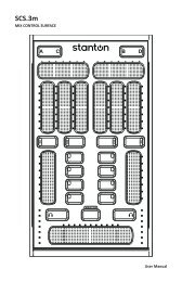
<strong>SMX.501</strong> FEATURES<br />
This hybrid 3-Channel, "Techno /<br />
Scratch" mixer will appeal to both<br />
Turntablist and Club/Rave DJs alike.<br />
Nowhere else can DJs find so many<br />
features included with the design of a<br />
battle mixer. The <strong>SMX.501</strong> is a "one of<br />
a kind" mixer that combines the best of<br />
both worlds and bridges the gap<br />
between Battle & Club DJs.<br />
• 3-channel scratch mixer<br />
• Assign effects loop to each individual channel, plus the mic<br />
• Custom High Quality P&G (Penny & Giles) Crossfader with VCA curve<br />
adjustment and crossfader assign<br />
• Assignable Crossfader (A, B, Bypass)<br />
• VCA Crossfader curve control and reverse<br />
• Curve control and reverse on Linefaders<br />
• Each channel features a gain control, slider Pan, and a versatile<br />
3-band EQ with complete KILL<br />
• Balanced XLR master output (unbalanced RCA also provided)<br />
• Booth output<br />
• Rotatable 3 Position phono/line switch with flash feature<br />
• Separate channel input and master output LED meters<br />
• Headphone mute<br />
• Dual headphone outputs (1/4"/6.3mm and 1/8"/3.5mm)<br />
• Fully assignable Send/Return connections for external effects<br />
• Pre Fader Listen (PFL) of channels and effects loop with Cue Pan control<br />
• 3 line, 3 phono, and 2 mic inputs<br />
• Mic channel features gain controls and a 3-band EQ<br />
• Channel fader reverse switch<br />
• Protekt Panel<br />
• User replaceable faders<br />
• OS2 compatible
DESCRIPTION OF FUNCTIONS
DESCRIPTION OF FUNCTIONS<br />
CHANNEL STRIPS<br />
GAIN<br />
Controls the input level of each channel. An LED meter is provided<br />
on each of the 3 channels.<br />
HI, MID, LOW (EQ)<br />
Individual controls for high frequency, midrange, and low frequency<br />
equalization with +9dB/Kill adjustments. Note: Any<br />
changes made to EQ settings will change the overall output<br />
level.<br />
CURVE<br />
The Line Fader Curve Control adjusts the curve of the input<br />
faders between short, mid, or long fade.<br />
PAN<br />
Controls left/right output balance of each channel.<br />
REV<br />
Reverses the direction of each line channel fader. When the line<br />
fader reverse function is engaged, the volume for that channel<br />
will be full when the fader is down. As the fader moves upward,<br />
the volume will decrease.<br />
FX<br />
This is an ON/OFF switch for the effects loop. The level is controlled<br />
by the Send and Return knobs. See Master Section for<br />
details.<br />
INPUT SELECT<br />
These toggle switches select the input source between phono<br />
and line for each channel. The FLASH position can be used for<br />
transforming and scratching effects.<br />
LINE FADER<br />
Controls the output volume of each channel. The signal is routed<br />
to the line faders after the gain, EQ, pan, and effects.
DESCRIPTION OF FUNCTIONS<br />
MASTER SECTION<br />
MASTER<br />
Controls the overall output level of the mixer.<br />
SEND RETURN<br />
Send and Return levels are used to control the volume of the<br />
external effects unit connected to the <strong>SMX.501</strong> using the effects<br />
loop. SEND is the level of the signal sent to the effect unit, and<br />
RETURN is the level of the processed signal returning from the<br />
the effects unit.<br />
BOOTH LEVEL<br />
Controls the output level for the booth output. This is basically a<br />
2nd output. It is usually used for monitoring in a DJ booth, but can<br />
be used for various applications.<br />
CUE PAN<br />
Fades the headphone output between the PFL signal (selected by<br />
the Cue Select buttons) and master output, effectively allowing<br />
the user to preview a mix.<br />
CUE SELECT<br />
Selects the channel(s) - 1, 2, or 3 - to be previewed in the headphones.<br />
CFX (Cue FX)<br />
Routes the signal from the effects to the headphones allowing<br />
the user to preview the effects mix in the headphones.<br />
MFX (Master FX)<br />
Routes the signal sent to the master output through the effects<br />
loop. This simply means that all audio coming out of the mixer<br />
will be processed. This is very useful for effects such as filters or<br />
compressors.
DESCRIPTION OF FUNCTIONS<br />
MICROPHONE SECTION<br />
MIC 1<br />
Controls the input level of Microphone input 1.<br />
MIC 2<br />
Controls the input level of Microphone input 2.<br />
HI, MID, LOW (EQ)<br />
Individual controls for high frequency, midrange, and low frequency<br />
equalization with +9dB/Kill adjustments. The EQ controls<br />
both Microphone inputs. Note: Any changes made to EQ settings<br />
will change the overall output level.<br />
FX<br />
This is an ON/OFF switch for the effects loop. The level is controlled<br />
by the Send and Return knobs. See Master Section for<br />
details.<br />
FRONT<br />
CURVE<br />
The Crossfader Curve Control adjusts the curve of the fader from<br />
a short cut to a long fade.<br />
CROSSFADER ASSIGN<br />
This is used to assign a channel to either side of the crossfader<br />
or to bypass it. A is the left side, B is the right side.<br />
CUE LEVEL<br />
Controls the volume of the headphone output.<br />
HEADPHONE MUTE<br />
This is a mute button that can be used to turn off the headphones<br />
without readjusting the volume.<br />
HEADPHONES<br />
This is the headphone output jack to connect your headphones.
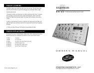
FADER CLEANING AND REPLACEMENT<br />
After constant use the <strong>SMX.501</strong> faders may need to be cleaned and lubricated<br />
from time to time. This will ensure long life and keep a smooth feeling throughout<br />
the fader's lifetime. Follow the instructions below to lubricate and clean your<br />
faders:<br />
Removing a fader:<br />
1. Make sure mixer is powered off and power supply is<br />
disconnected from back of mixer.<br />
2. To remove the Protekt Panel, take off the 4 main<br />
fader knobs and then remove the 4 screws located<br />
at the corners of the panels. Lift the panel to<br />
remove.<br />
3. Remove the fader to be cleaned or replaced by<br />
unscrewing the 2 outer screws on the fader plate<br />
(removing the 2 inner screws will detach the fader<br />
from the fader plate).<br />
4. Disconnect the fader from mixer by removing the 4pin<br />
connector on the bottom of the fader.<br />
Installing a fader:<br />
1. Once original fader has been removed, simply plug<br />
the 4-pin connector into the new fader.<br />
2. There is a recessed button on the left end of the<br />
front panel which switches the mixer circuit between a<br />
standard fader and the Focus Fader (not included).<br />
Use a pin or thin screwdriver to access the button.<br />
When the LED above the button is lit, the Focus Fader<br />
circuit is engaged. When using a P&G fader, make<br />
sure the LED is off.<br />
3. Place fader back in mixer and replace 2 outer screws to secure fader.<br />
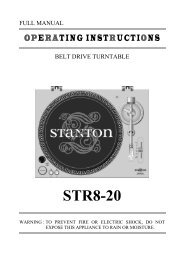
Cleaning a Penny & Giles fader:<br />
1. Remove 2 mounting screws from fader plate. (NOTE: The P&G fader is<br />
designed with floating mounting threads for precise mechanical centralizing of<br />
the fader. If you desire to keep your fader`s current mounting position we suggest<br />
that you make 2 marks on both ends of the<br />
fader on the fader plate to indicate the P&G fader<br />
position.) See Figure 1.<br />
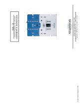
2. Once fader is removed from unit, remove the two<br />
screws (A) from the end of the fader body where<br />
the wires exit the fader casing. Pull away the end<br />
block. Withdraw the dust cover (B). Taking great<br />
care, remove the slider assembly (C), ensuring that<br />
the wiper contacts (D) are not damaged as this will<br />
Figure 1
DESCRIPTION OF FUNCTIONS<br />
affect the operation of the fader. Clean<br />
the slider assembly by gently wiping<br />
the wiper contacts and slider<br />
bearings (E) using a tissue or cotton<br />
bud. If slider bearings are<br />
excessively worn, as indicated by<br />
excessive slider rocking then contact<br />
<strong>Stanton</strong> for replacement.<br />
3. Remove the single upper screw on<br />
the opposite end block to remove the guide rail.<br />
Clean the guide rail (F) with a tissue or cloth,<br />
removing all traces of dirt and contamination.<br />
4. Remove the fader track (G) by slowly withdrawing<br />
from the unit. Place fader track on desk or<br />
working surface with black contacts facing upwards. If necessary,<br />
the track can be washed in warm water, wiped gently then dried<br />
thoroughly using a dry cloth. Use a lint free cloth or swab to wipe<br />
the tracks and check for marks along the track. (Note: Lint free<br />
cloth should be used to avoid dust/fibers being deposited on the<br />
track). If the track appears excessively worn, or if cleaning does<br />
not improve operation, replacement may be necessary.<br />
5. Examine the center channel of the fader body and if dirty, clean<br />
using cotton buds.<br />
6. Re-assemble and lubricate the fader as follows:<br />
6.1) Secure the end block and guide rail onto the fader body.<br />
6.2) Insert track into the fader body.<br />
6.3) Insert slider assembly onto guide rail and into the fader body. Move slider<br />
from end to end to disperse the oil evenly. Carefully wipe away any excess<br />
oil using a tissue or cloth.<br />
6.4) Lubricate the guide rail by placing one drop of silicon liquid oil onto the<br />
guide rail (F).<br />
6.5) Insert dust cover.<br />
6.6) Insert fader track back into fader body with wires coming out open end of<br />
fader body.<br />
6.7) Secure the remaining end block ensuring that the track wires (I) are not<br />
pinched between the end block and fader casing.<br />
7. Once assembled, move the slider from end to end to ensure operation is<br />
smooth.<br />
8. Attach fader to fader plate. (NOTE: As noted earlier if you do not want to<br />
change positioning of fader, keep the 2 fader plate screws loose and shift the<br />
fader until it is aligned with the marks you created in step 1, then tighten fader<br />
plate screws.)<br />
A<br />
B<br />
G<br />
F<br />
C<br />
G<br />
D<br />
I<br />
E
TECHNICAL SPECIFICATIONS<br />
Line inputs: 2 (RCA) x 3 channels, -10 dBV /10 kOhm<br />
Phono inputs: 2 (RCA) x 3 channels, -50 dBV / 47 kOhm<br />
Mic inputs: 2 (1/4") -50 dBV /100 kOhm<br />
Return inputs: 2 (1/4"), -10 dBV / 10 kOhm<br />
Send output: 2 (1/4"), -10 dBV<br />
Master output: 2 (XLR Balanced/RCA unbalanced),<br />
+4 dBu balanced / -10 dBV unbalanced<br />
Record output: 2 (RCA), -10 dBV / 100 Ohms<br />
Booth output: 2 (RCA), -10 dBV / 100 Ohms<br />
Headphone output: 1 (1/4 inch), greater than 32 Ohm load<br />
Frequency Response: 20 Hz - 20 kHz, + 0.5/-2 dB<br />
Tone Control : + 9/-40 dB (Hi, Mid, Low)<br />
Max Gain: 14 dB<br />
S/N Ratio: Better than 100 dB (ref: max input level)<br />
T.H.D Less than 0.05% (1 kHz)<br />
Dimension(LxWxD): 14" x 10.25" x 4.75"; 355 x 260 x 120 )mm<br />
Weight: 9.25 lbs 4.2 kgs<br />
REPLACEMENT PARTS<br />
The following user replaceable parts are available from your local<br />
<strong>Stanton</strong> dealer.<br />
LF501 Channel input fader<br />
CF-PG110 Penny & Giles crossfader<br />
CF-F2 Focus Fader V2<br />
OS2 Optical Scratch Switch (phono/line selector)<br />
PP501 PROTEKT panel<br />
PS-RM19US US Power Supply (110v)<br />
PS-RM19EU European Power Supply (220v)<br />
PS-RM19UK UK only Power Supply (240v)
WARRANTY<br />
<strong>Stanton</strong> Magnetics, Inc. – Warranty Provision – Returns for Repairs or Replacement<br />
Warranty<br />
Through <strong>Stanton</strong>’s authorized dealers around the World, <strong>Stanton</strong>, or one of <strong>Stanton</strong>’s<br />
authorized distributors outside the U.S., will, without charge, repair or replace, at the sole<br />
discretion of the entity responsible for making the repair or providing the replacement, any<br />
<strong>Stanton</strong> merchandise proved defective in material or workmanship for a period of one (1)<br />
following the date of original purchase. Exceptions to this warranty are as noted below:<br />
The warranty for mechanical parts which are subject to wear and tear are limited to the earlier<br />
to occur of thirty (30) days following the date of original purchase or the following number<br />
of cycles: Faders - 15,000; Rotary potentiometers - 10,000; and Switches - 10,000.<br />
<strong>Stanton</strong> will warrant all replacement parts and repairs for ninety (90) days from the date of<br />
original shipment. Repairs made necessary by reason of misuse, alteration, normal wear, or<br />
accident are not covered under this warranty.<br />
Returns<br />
Authorized <strong>Stanton</strong> dealers are only authorized to sell and distribute merchandise within a<br />
specific country. All goods requiring warranty repair or replacement must be returned (freight<br />
prepaid if not hand-delivered) to the authorized <strong>Stanton</strong> dealer from whom the merchandise<br />
was purchased and in the same country where the merchandise was purchased. For purposes<br />
of purchases made via the Internet, the merchandise must be returned to the authorized<br />
<strong>Stanton</strong> dealer in the country where the authorized <strong>Stanton</strong> dealer which sold the merchandise<br />
to purchaser is located and not the authorized <strong>Stanton</strong> dealer in the country where<br />
the purchaser is located or the country in which the merchandise was received. Any returns<br />
to a non-authorized dealer or to an authorized <strong>Stanton</strong> dealer not in the same country as<br />
the merchandise was intended to be sold or as set forth above will void this warranty.<br />
To initiate a warranty repair, you must contact the authorized <strong>Stanton</strong> dealer from whom you<br />
purchased the merchandise, and follow such authorized <strong>Stanton</strong> dealer’s return policy.<br />
<strong>Stanton</strong> assumes no risk and shall be subject to no liability for damages or loss resulting<br />
from the specific use or application made of the merchandise. <strong>Stanton</strong>'s liability for any<br />
claim, whether based on breach of contract, negligence, infringement of any rights of any<br />
party, or product liability, and relating to the merchandise shall not exceed the price received<br />
by <strong>Stanton</strong> from your purchase of such merchandise. In no event will <strong>Stanton</strong> be liable for<br />
any special, incidental or consequential damages (including loss of use, loss of profit and<br />
claims of third parties) however caused, whether by the negligence of <strong>Stanton</strong> or otherwise.<br />
To the extent permitted by law and except as otherwise provided above, <strong>Stanton</strong> disclaims<br />
any express or implied warranties of merchantability or fitness for a particular purpose.<br />
The above warranty provides you with specific legal rights. You may also have additional<br />
rights, which are subject to variation from state to state and country to country.<br />
If there is a dispute regarding the warranty of merchandise that does not fall under the warranty<br />
conditions stated above, please include a written explanation with the merchandise<br />
when returned pursuant to the terms and conditions set forth herein.<br />
Please register your product online at www.stantondj.com or mail your completed warranty<br />
card to:<br />
<strong>Stanton</strong> Magnetics, Inc, 3000 SW 42 St. Hollywood, Florida 33312.