

OMB-DBK Option Cards and Modules - Omega Engineering
OMB-DBK Option Cards and Modules - Omega Engineering
OMB-DBK Option Cards and Modules - Omega Engineering

You also want an ePaper? Increase the reach of your titles
YUMPU automatically turns print PDFs into web optimized ePapers that Google loves.
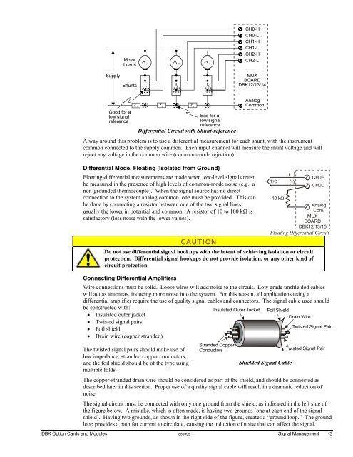
Differential Circuit with Shunt-reference<br />
A way around this problem is to use a differential measurement for each shunt, with the instrument<br />
common connected to the supply common. Each input channel will measure the shunt voltage <strong>and</strong> will<br />
reject any voltage in the common wire (common-mode rejection).<br />
Differential Mode, Floating (Isolated from Ground)<br />
Floating-differential measurements are made when low-level signals must<br />
be measured in the presence of high levels of common-mode noise (e.g., a<br />
non-grounded thermocouple). When the signal source has no direct<br />
connection to the system analog common, one must be provided. This can<br />
be done by connecting a resistor between one of the two signal lines;<br />
usually the lower in potential <strong>and</strong> common. A resistor of 10 to 100 kΩ is<br />
satisfactory (less noise with the lower values).<br />
CAUTION<br />
T/C<br />
10 kΩ<br />
(+)<br />
(-)<br />
CH0H<br />
CH0L<br />
Analog<br />
Com.<br />
MUX<br />
BOARD<br />
<strong>DBK</strong>12/13/15<br />
Floating Differential Circuit<br />
Do not use differential signal hookups with the intent of achieving isolation or circuit<br />
protection. Differential signal hookups do not provide isolation, or any other kind of<br />
circuit protection.<br />
Connecting Differential Amplifiers<br />
Wire connections must be solid. Loose wires will add noise to the circuit. Low grade unshielded cables<br />
will act as antennas, inducing more noise into the system. For this reason, all applications using a<br />
differential amplifier require the use of quality signal cables <strong>and</strong> connectors. The signal cable used should<br />
be constructed with: Insulated Outer Jacket Foil Shield<br />
• Insulated outer jacket<br />
• Twisted signal pairs<br />
• Foil shield<br />
• Drain wire (copper str<strong>and</strong>ed)<br />
The twisted signal pairs should make use of<br />
low impedance, str<strong>and</strong>ed copper conductors;<br />
<strong>and</strong> the foil shield should be of the type using<br />
multiple folds.<br />
Str<strong>and</strong>ed Copper<br />
Conductors<br />
Shielded Signal Cable<br />
Drain Wire<br />
Twisted Signal Pair<br />
Twisted Signal Pair<br />
The copper-str<strong>and</strong>ed drain wire should be considered as part of the shield, <strong>and</strong> should be connected as<br />
described later in this section. Proper use of a quality signal cable will result in a dramatic reduction of<br />
noise.<br />
The signal circuit must be connected with only one ground from the shield, as indicated in the left side of<br />
the figure below. A mistake, which is often made, is having two grounds (one at each end of the signal<br />
shield). Having two grounds, as shown in the right side of the figure, creates a “ground loop.” The ground<br />
loop provides a path for current to circulate, causing the induction of noise that can affect the signal.<br />
<strong>DBK</strong> <strong>Option</strong> <strong>Cards</strong> <strong>and</strong> <strong>Modules</strong> 886995 Signal Management 1-3


