

OMB-DBK Option Cards and Modules - Omega Engineering
OMB-DBK Option Cards and Modules - Omega Engineering
OMB-DBK Option Cards and Modules - Omega Engineering

You also want an ePaper? Increase the reach of your titles
YUMPU automatically turns print PDFs into web optimized ePapers that Google loves.
System Noise<br />
Electrical noise can present problems even with good equipment; thus, controlling noise is imperative.<br />
Some techniques avoid or prevent noise sources from entering the system; other techniques remove noise<br />
from the signal.<br />
Laboratory <strong>and</strong> industrial environments often have multiple sources of electrical noise. An AC power line<br />
is a source of 50/60 Hz noise. Heavy equipment (air conditioners, elevators, pumps, etc.) can be a source<br />
of noise, particularly when turned on <strong>and</strong> off. Local radio stations are a source of high-frequency noise,<br />
<strong>and</strong> computers <strong>and</strong> other electronic equipment can create noise in a multitude of frequency ranges. Thus,<br />
an absolute noise-free environment for data acquisition is not realistic. Fortunately, noise-reduction<br />
techniques such as averaging, filtering, differential voltage measurement, <strong>and</strong> shielding are available to<br />
reduce noise to an acceptable level.<br />
Note: Additional noise-reduction information is contained in the section, “Signal Modes,” especially in the<br />
paragraphs pertaining to connections, signal cables, <strong>and</strong> ground loops.<br />
Averaging<br />
Averaging is done in software after several samples have been collected. Depending on the nature of the<br />
noise, averaging can reduce noise by the square root of the number of averaged samples. Although<br />
averaging can be effective, it suffers from several drawbacks. Noise in measurements only decreases as<br />
the square root of the number of measurements—reducing RMS noise significantly may require many<br />
samples. Thus, averaging is suited to low-speed applications that can provide many samples.<br />
Note: Only r<strong>and</strong>om noise is reduced or eliminated by averaging. Averaging will not reduce or eliminate<br />
any signal that is periodic.<br />
Analog Filtering<br />
A filter is an analog circuit element that attenuates an incoming signal according to its frequency. A lowpass<br />
filter attenuates frequencies above the cutoff frequency. Conversely, a high-pass filter attenuates<br />
frequencies below the cutoff. As frequency increases beyond the cutoff point, the attenuation of a singlepole,<br />
low-pass filter increases slowly. Multi-pole filters provide greater attenuation beyond the cutoff<br />
frequency but may introduce phase (time delay) problems that could affect some applications.<br />
Filter circuits can be active or passive:<br />
• Active. The <strong>DBK</strong>18 Low-Pass Filter Card has an instrumentation amplifier with variable gain <strong>and</strong><br />
filter configurations. The <strong>DBK</strong>18 uses an active 3-pole filter (mostly contained within the UAFF42<br />
ICs) that can be configured as a Butterworth, Bessel, or Chebyshev filter with corner frequencies up<br />
to 50 kHz. Filter properties depend on the values of resistors <strong>and</strong> capacitors. These components<br />
can be changed by the user.<br />
• Passive. The <strong>DBK</strong>11 has a prototype area on the PC board for attaching non-powered components<br />
such as resistors <strong>and</strong> capacitors. The user chooses component values to produce the desired<br />
properties.<br />
Input <strong>and</strong> Source Impedance<br />
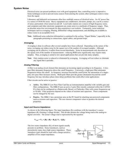
As shown in the following figure, The input impedance (Ri) combines with the transducer’s source<br />
impedance (Rs) forming a voltage divider. This divider distorts the voltage being read at the analog-todigital<br />
converter. The actual voltage read is represented by the equation:<br />
Vread = VT × [Ri / (Ri + Rs)] [ Vt - IbRs)<br />
The low source impedance (Rs) of most signals usually<br />
presents no problem. Some transducers, such as<br />
piezoelectric types, have high source impedance. These<br />
transducer types should be used with a charge-sensitive<br />
amplifier of low output impedance.<br />
<strong>DBK</strong> <strong>Option</strong> <strong>Cards</strong> <strong>and</strong> <strong>Modules</strong> 886995 Signal Management 1-5


