

OMB-DBK Option Cards and Modules - Omega Engineering
OMB-DBK Option Cards and Modules - Omega Engineering
OMB-DBK Option Cards and Modules - Omega Engineering

You also want an ePaper? Increase the reach of your titles
YUMPU automatically turns print PDFs into web optimized ePapers that Google loves.
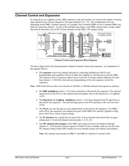
Channel Control <strong>and</strong> Expansion<br />
In a Daq device or LogBook system, <strong>DBK</strong> expansion cards <strong>and</strong> modules can increase the number of analog<br />
input channels from 16 base channels to 256 input channels (16 × 16). The configuration will vary<br />
depending on the <strong>DBK</strong>’s channel capacity; for example, four 4-channel <strong>DBK</strong>s or two 8-channel <strong>DBK</strong>s can<br />
share the same base channel. As part of the multiplexing scheme, each <strong>DBK</strong> card provides a single output<br />
that must be directed to one of the 16 base channels via the <strong>DBK</strong>’s JP1 jumper setting.<br />
<strong>DBK</strong> card or module<br />
16<br />
expansion MUX PGA<br />
16<br />
base MUX PGA<br />
channels<br />
channels<br />
2<br />
JP1<br />
channel<br />
select<br />
jumper<br />
4 2 bits select 1 of 4 gains<br />
4 bits select 1 of 16 inputs<br />
P1 P1<br />
4 bits select<br />
1 of 16<br />
inputs<br />
4<br />
Sequencer<br />
Channel Control <strong>and</strong> Expansion Block Diagram<br />
Daq device System<br />
or LogBook System<br />
2<br />
2 bits select<br />
1 of 4 gains<br />
ADC<br />
100 kHz<br />
Clock<br />
The above figure shows the functional parts related to channel control <strong>and</strong> expansion. An explanation of<br />
the diagram follows.<br />
• The sequencer selects the channel <strong>and</strong> gain by controlling multiplexers (MUX) <strong>and</strong><br />
programmable gain amplifiers (PGA) in either the LogBook or the Daq device <strong>and</strong> the <strong>DBK</strong>.<br />
The sequencer uses 4 expansion address lines to provide 16 unique channel addresses for each<br />
base channel. A 100 kHz clock <strong>and</strong> user programming of the scan sequence control the<br />
sequencer.<br />
Note: /2000 Series Devices allow for selection of 100 kHz, or 200 kHz internal clock speed via software.<br />
• The <strong>DBK</strong> multiplexer selects 1 of 16 (max) channels as directed by the sequencer. The selected<br />
signal travels to the PGA, to the channel-selection jumper, then to the Daq device, or LogBook<br />
via P1.<br />
• The Daq device or LogBook multiplexer selects 1 of 16 base channels from P1 input lines as<br />
directed by the sequencer. The selected signal goes to the PGA <strong>and</strong> then to the A/D converter<br />
(A/D).<br />
• The PGAs can vary the gain on a per channel basis as directed by the sequencer. For <strong>DBK</strong>s<br />
with a PGA, the sequencer can combine the gains of the <strong>DBK</strong> PGA <strong>and</strong> the LogBook or Daq<br />
device PGA for a variety of gain settings.<br />
• The P1 interface has a signal line for each of the 16 base channels <strong>and</strong> control lines for gain<br />
setting (pins 5, 6) <strong>and</strong> sub-channel selection (pins 3, 4, 22, 23).<br />
• The JP1 channel select jumper in the <strong>DBK</strong> can be placed on pins for channel 0 through<br />
channel 15. Until the base channel capacity is filled (16 max), multiple cards can use the same<br />
JP1 channel setting if their DIP switches are set to identify unique sub-channel card numbers.<br />
Note: The channel select header on <strong>DBK</strong>17 <strong>and</strong> <strong>DBK</strong>18 is labeled J1 instead of JP1.<br />
<strong>DBK</strong> <strong>Option</strong> <strong>Cards</strong> <strong>and</strong> <strong>Modules</strong> 886995 Signal Management 1-7


