Standard Operating Procedure (SOP) for Compliance Monitoring ...
Standard Operating Procedure (SOP) for Compliance Monitoring ...
Standard Operating Procedure (SOP) for Compliance Monitoring ...
You also want an ePaper? Increase the reach of your titles
YUMPU automatically turns print PDFs into web optimized ePapers that Google loves.
Application of the CEMS at Thermal Power Plants<br />
1. Emissions <strong>Monitoring</strong><br />
Continuous Emissions <strong>Monitoring</strong> Systems (CEMS) are automated instrument systems that measure<br />
the amount of a pollutant in a gas stream. At thermal power plants, instrumentation to monitor the flue<br />
gas O 2 and carbon monoxide (CO) concentrations or the carbon dioxide (CO 2 ) concentration is<br />
routinely used as part of the control system to optimise the combustion efficiency. Additional<br />
monitoring systems can be installed and operated to measure concentrations of pollutants in the flue<br />
gases vented through the stack into the atmosphere. This annex presents background in<strong>for</strong>mation<br />
about the use of CEMS <strong>for</strong> measuring sulphur dioxide (SO 2 ), nitrogen oxides (NO x ), and PM<br />
emissions in combustion flue gases and discusses the application of these monitoring systems at<br />
thermal power plants in the United States. This overview of emissions monitoring technologies and<br />
analyser manufacturers used by the electric utility industry <strong>for</strong> complying with the CEMS regulations<br />
is intended to provide relevant in<strong>for</strong>mation to assist with the application of CEMS to thermal power<br />
plants in Abu Dhabi and other locations in United Arab Emirates (UAE).<br />
1.1 SO 2 and NO x Emissions <strong>Monitoring</strong><br />
This section of Annex 1 presents background in<strong>for</strong>mation about the use of CEMS to measure SO 2 and<br />
NO x emissions in combustion flue gases and discusses the potential application of these monitoring<br />
systems to thermal power plants in the size range currently in use or to be built at facilities in Abu<br />
Dhabi. The in<strong>for</strong>mation in Annex 1 was presented in a report prepared by J.R. Jernigan and presented<br />
at the 7th International Conference on Emissions <strong>Monitoring</strong>, which was held in Paris, France, in<br />
February 2006. The report presents an overview of the SO 2 and NO x CEMS installed at U.S. electric<br />
utility power plants as part of the requirements under the U.S. Environmental Protection Agency’s<br />
(U.S. EPA’s) program to control acid rain in the eastern United States.<br />
More than 3,000 CEMS have been installed and certified at U.S. electric utility power plants to meet<br />
the requirements of national emissions standards and emissions trading programs. The use of these<br />
CEMS has resulted in extensive experience being gained by the U.S. electric utility industry regarding<br />
the most reliable air pollution emissions monitoring technologies and analyser manufacturers. Over<br />
the years, the availability of more reliable pollutant analysers, including flue gas flow rate and<br />
moisture monitors, has increased significantly. As a result of the continuous monitoring regulatory<br />
requirements, the demand <strong>for</strong> extremely accurate and reliable equipment <strong>for</strong> CEMS has also increased<br />
to meet the tighter precision and reliability requirements specified. The monitoring instrumentation<br />
available today is based on improved analytical techniques and is equipped with enhanced electronics,<br />
programmable software capabilities, and troubleshooting diagnostics.<br />
1.1.1 Sample Acquisition Techniques<br />
A CEMS used to measure SO 2 and NO x emissions incorporates one of three sample acquisition<br />
systems: dilution-extractive, non-dilution extractive (i.e., sampling without dilution of the sample<br />
gas), and in situ. Inherent differences exist among the three sampling techniques, and thus each<br />
technique has distinct strengths and weaknesses, which should be carefully evaluated when selecting<br />
an appropriate technique <strong>for</strong> a specific application. The sample acquisition techniques chosen by<br />
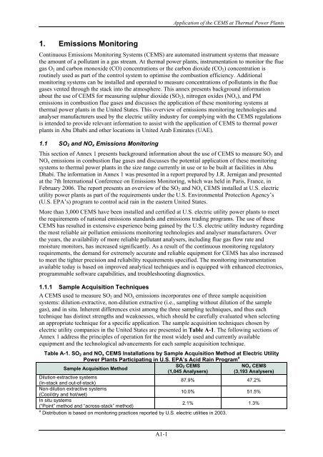
electric utility companies in the United States are presented in Table A-1. The following sections of<br />
Annex 1 address the principles of operation <strong>for</strong> the most widely used and currently available<br />
equipment and the technological advancements <strong>for</strong> each sample acquisition technique.<br />
Table A-1. SO 2 and NO x CEMS Installations by Sample Acquisition Method at Electric Utility<br />
Power Plants Participating in U.S. EPA’s Acid Rain Program a<br />
Sample Acquisition Method<br />
SO 2 CEMS<br />
(1,045 Analysers)<br />
NO x CEMS<br />
(3,193 Analysers)<br />
Dilution-extractive systems<br />
(In-stack and out-of-stack)<br />
87.9% 47.2%<br />
Non-dilution extractive systems<br />
(Cool/dry and hot/wet)<br />
10.0% 51.5%<br />
In situ systems<br />
(“Point” method and “across-stack” method)<br />
2.1% 1.3%<br />
a Distribution is based on monitoring practices reported by U.S. electric utilities in 2003.<br />
A1-1


