Connectors for Timber and Masonry Construction - Simpson Strong ...
Connectors for Timber and Masonry Construction - Simpson Strong ...
Connectors for Timber and Masonry Construction - Simpson Strong ...

You also want an ePaper? Increase the reach of your titles
YUMPU automatically turns print PDFs into web optimized ePapers that Google loves.
<strong>Connectors</strong><br />
<strong>for</strong> <strong>Timber</strong><br />
<strong>and</strong> <strong>Masonry</strong><br />
<strong>Construction</strong><br />
2013 Edition<br />
C-UK12<br />
+44 (0) 1827 255 600<br />
www.strongtie.co.uk
<strong>Connectors</strong> <strong>for</strong> <strong>Timber</strong> <strong>and</strong> <strong>Masonry</strong> <strong>Construction</strong><br />
Alphabetical Index<br />
SST Prefix Description Page<br />
1ARB Arrisrail Bracket 142<br />
1EXT Wall Extension Profile 129<br />
1FUR Wall Extension Profile 129<br />
1MPP Galvanised Wall Extension Profile 129<br />
1MPS Stainless Steel Wall Extension Profile 129<br />
A Angles 111<br />
A34/A35 Framing Anchor/Universal Framing Anchor 110<br />
ABC Angle Bracket <strong>for</strong> Cladding 117<br />
ABR Rein<strong>for</strong>ced Angle Bracket 114<br />
Arch<strong>for</strong>mers 140<br />
BI Top Flange I-Joist Hanger 67<br />
BTS Brick-<strong>Timber</strong> Stainless Steel Wall Tie 107, 131<br />
C2K Crocodile Wall Extension Profile 128<br />
CB Welded Column Base 120<br />
CBR <strong>Masonry</strong> Rein<strong>for</strong>cement Mesh 137<br />
CC Column Cap 121<br />
DBT Deck Board Tie 143<br />
Disproportionate Collapse 10<br />
DML Exp<strong>and</strong>ed Metal Lathing 138<br />
DSTC Double Sided <strong>Timber</strong> Connector 119<br />
E Rein<strong>for</strong>ced Angle Bracket 114<br />
EA Light rein<strong>for</strong>ced Angle Bracket 115<br />
EC Light Angle Bracket 115<br />
EFIXR/EFIXS Adjustable Angle Bracket 116<br />
END Multi Angle Bracket 116<br />
EPC End Post Cap 121<br />
ERS Render Stop 136<br />
ES Nail Plate Angle Bracket 116<br />
ET Skewed 45° Hanger 49, 80<br />
ETFSS Hold Down Strap 106<br />
FB Fixing B<strong>and</strong> 127<br />
FMS Folded Mini Strap 126<br />
FT Frame Tie 130<br />
GLTV Top Flange Heavy Welded Hanger 69<br />
GS Glide Shoe 92<br />
H High Wind Tie 118<br />
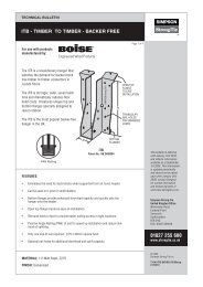
H Heavy Restraint Strap 124<br />
HES Heavy Engineered Restraint Strap 122<br />
HGUQ Face Fix Heavy Girder Truss Hanger - SDS Installation 87<br />
HGUS Face Fix Heavy EWP Hanger 80<br />
HGUS Face Fix Heavy Girder Truss Hanger 87<br />
HI Scrolled Hip Iron 142<br />
HITB Heavy Backer Free I-Joist Hanger 52<br />
HIU Face Fix Heavy I-Joist Hanger 75<br />
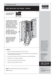
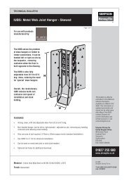
HIUB Heavy Metal-Web Hanger 82<br />
HJHM Heavy <strong>Masonry</strong> Solid Joist Hanger 21<br />
HJHMI Heavy <strong>Masonry</strong> I-Joist Hanger 30<br />
HRC Hip Ridge Connector 100<br />
HSA Herringbone Joist Strut 127<br />
HU Heavy Face Fix I-Joist Hanger 78<br />
IC Insulation Clip 108<br />
ICF Ledger Connector 28<br />
IHS I-Beam Hole Support 58<br />
IRC Insulated Concrete Form Hanger 131<br />
ITB Backer Free I-Joist Hanger 52<br />
ITBS Backer Free I-Joist Hanger With Adjustable Skew 54<br />
ITSE Top Flange I-Joist Hanger 64<br />
IUB Face Fix Metal-Web Hanger 82<br />
IUBS Metal-Web Joist with Adjustable Skew 86<br />
IUC Face Fix Concealed Flange Hanger 44<br />
IUQ Metal Web Joist to SIP Hanger 88<br />
IUSE Face Mount I-Joist Hanger 71<br />
JES<br />
Joist End Support<br />
90<br />
JHA Joist Hanger with Adjustable Height 42<br />
JHM <strong>Masonry</strong> Joist Hanger 25<br />
JHMI <strong>Masonry</strong> I-Joist Hanger 30<br />
L Light Restraint Strap 124<br />
SST Prefix Description Page<br />
L70 Rein<strong>for</strong>cing Angle 111<br />
LBV Top Flange I-Joist Hanger 67<br />
LES Light Engineered Restraint Strap 122<br />
LS Skewable Angle 119<br />
LSSU Light Sloped/Skewed Adjustable Hanger 98<br />
LSTA Strap Tie 127<br />
LSU Light Sloped/Skewed Adjustable Hanger 98<br />
LTS/MTS Light/Medium Twist Strap 127<br />
LUP Light Speed Prong Joist Hanger 48<br />
LWTS Brick-to-Brick Stainless Steel Wall Tie 130<br />
MH Mini Joist Hanger 48<br />
MH Mini Hanger I-Joist 77<br />
MIT Medium Top Flange I-Joist Hanger 65<br />
MIU Medium Face Fix I-Joist Hanger 75<br />
MJC Multi Joist Connector 61<br />
MMB Mini Mesh Bead 137<br />
MP Mending Plate 143<br />
MVB Movement Bead 136<br />
NAILS Nail Types <strong>and</strong> Nailing Options 14<br />
NP Nail Plate 97<br />
NS Nail Stopper 142<br />
PBH Heavy Duty Post Base 121<br />
PBS Post Base with St<strong>and</strong> Off 120<br />
PC Post Cap 121<br />
PEB Plasterboard Edge Bead 136<br />
PSB Plaster Stop Bead 136<br />
PVCu Bead Plastic Bead 128<br />
PWT Party Wall Tie 109<br />
RBL Ribbed Metal Lathing 139<br />
RR Ridge Rafter Connector 101<br />
SAB St<strong>and</strong>ard Angle Bead 137<br />
Sacrificial Joist Detail 71<br />
SAE Heavy Face Fix Hanger 46<br />
SAI Heavy Face Fix Hanger with Concealed Flanges 46<br />
SDE Adjustable Face Fix Hanger 45<br />
SDW Structural <strong>Timber</strong> Screws 16<br />
SES <strong>Simpson</strong> End Seal 34<br />
SFH Safety Fast Hanger 18<br />
SFHI Safety Fast Hanger <strong>for</strong> I-Joist 39<br />
SFJC Safety Fast Joist Cap 24, 33<br />
SFWH Safety Fast Welded Joist Hanger 18<br />
SFLH Safety Fast Lite Hanger <strong>for</strong> Solid Joist 20<br />
SFLHI Safety Fast Lite Hanger <strong>for</strong> I-Joist 36<br />
SFWHI Safety Fast Welded Joist Hanger <strong>for</strong> I-Joist 39<br />
SPA Sole Plate Anchor 105<br />
SPR Slope Adjustable Hanger 101<br />
SPWG Square Plate Washer 143<br />
SSTC Single Sided <strong>Timber</strong> Connector 113<br />
SVM Soffit Vent Mesh 140<br />
SWT Stainless Steel SIP Tie 107, 131<br />
T Bracket 119<br />
TCB Thin Coat Angle Bead 137<br />
TTCB Toothed Thin Coat Angle Bead 141<br />
TCP Truss Clip 92<br />
TFLS Levelling System 104<br />
THA Truss Hanger, Adjustable Height Strap 95<br />
THAI Adjustable Height I-Joist Hanger 81<br />
THG Girder Truss Hanger 96<br />
THM Truss Hanger Mono 94<br />
TU Concealed Beam Hanger 50<br />
U Face Fix Hanger <strong>for</strong> I-Joist 78<br />
VP Loft Vent Plate 91<br />
VPA Variable Pitch Connector 99<br />
VTCR Valley Truss Clip 102<br />
WBT Window Board Tie 130<br />
WPU Welded Top Flange EWP Hanger 69<br />
WTS Stainless Steel Wire Wall Tie 132<br />
ZS Slotted Z Clip 63<br />
2
<strong>Connectors</strong> <strong>for</strong> <strong>Timber</strong> <strong>and</strong> <strong>Masonry</strong> <strong>Construction</strong><br />
Connector Selector<br />
Products are divided into categories, identified by tabs along the page’s outer edge.<br />
<strong>Masonry</strong> Hangers - Solid Joist<br />
18-29<br />
<strong>Masonry</strong> Hangers - I-Joist & Metal Web<br />
30-41<br />
<strong>Timber</strong> Hangers - Solid Joist<br />
42-51<br />
<strong>Timber</strong> Hangers - I-Joist & Metal Web<br />
Roof <strong>Connectors</strong><br />
52-89<br />
90-102<br />
<strong>Timber</strong> Frame <strong>Connectors</strong><br />
104-109<br />
Angle Brackets & Ties<br />
110-117<br />
<strong>Timber</strong> <strong>Connectors</strong><br />
118-119<br />
Caps & Bases<br />
120-121<br />
Straps<br />
<strong>Masonry</strong> <strong>Connectors</strong> & Wall Ties<br />
Bead & Mesh<br />
Miscellaneous<br />
122-127<br />
128-133<br />
134-141<br />
142-143<br />
3
<strong>Connectors</strong> <strong>for</strong> <strong>Timber</strong> <strong>and</strong> <strong>Masonry</strong> <strong>Construction</strong><br />
New Products <strong>for</strong> 2012<br />
ABC: Angle Bracket <strong>for</strong> Cladding<br />
ET: 45° Skewed Left or Right Hanger<br />
Designed to fix<br />
vertical battens<br />
directly to the<br />
structure, creating<br />
an insulation/<br />
ventilation zone.<br />
One piece<br />
joist hanger <strong>for</strong><br />
supporting skewed<br />
timber joists from<br />
timber members.<br />
IC: Insulation Clip<br />
IHS: I-Beam Hole Support<br />
Provides a quick<br />
<strong>and</strong> simple method<br />
of retaining rigid<br />
insulation within a<br />
timber frame panel.<br />
Strengthens I-joists<br />
when holes are<br />
required to be cut<br />
in locations not<br />
normally permitted.<br />
IUQ: Metal Web Joist to SIP Hanger<br />
NP: Redesigned Nail Plate<br />
Provides a quick<br />
<strong>and</strong> simple method<br />
of retaining rigid<br />
insulation within a<br />
timber frame panel.<br />
All new Nail plate<br />
now manufactured<br />
from thicker<br />
material <strong>for</strong><br />
improved strength.<br />
SFLHI: Safety Fast Lite Hanger<br />
SPR: Slope Adjustable Hanger<br />
Supports timber<br />
joists from masonry<br />
walls without the<br />
need <strong>for</strong> masonry<br />
course above the<br />
course supporting<br />
the hanger.<br />
Supports joists or<br />
rafters from timber<br />
members. Can be<br />
sloped up or down<br />
by up to 45°.<br />
SVM: Soffit Vent Mesh<br />
A fine stainless<br />
steel mesh which<br />
allows roof space<br />
ventilation while<br />
preventing access<br />
to birds <strong>and</strong><br />
insects.<br />
SWT: Stainless Steel SIP Tie<br />
SIP wall tie used<br />
to restrain the<br />
external brickwork<br />
back to the building<br />
structure.<br />
4
Connection<br />
of Multi-Ply<br />
Members<br />
Using<br />
Structural<br />
Screws<br />
T-SCREW-0811<br />
Issued August 2011<br />
Also available from <strong>Simpson</strong> <strong>Strong</strong>-Tie ®<br />
Structural Screws. Designed to meet the needs of contractor’s building in timber frame, SIP<br />
(Structural Insulated Panel), CLT (Cross Laminated <strong>Timber</strong>), Glulam, but also <strong>for</strong> joining together<br />
multple truss plies <strong>and</strong> I-Beam, Open Web <strong>and</strong> solid joists.
<strong>Connectors</strong> <strong>for</strong> <strong>Timber</strong> <strong>and</strong> <strong>Masonry</strong> <strong>Construction</strong><br />
Eurocode 5: The New Design Method<br />
Background<br />
In 1985 a “New Approach to Technical Harmonisation” was introduced through the European Commission (EC). A list<br />
of Directives was <strong>for</strong>mulated <strong>for</strong> a wide range of product types. E.g. electrical goods, toys...<br />
One of these Directives was the <strong>Construction</strong> Products Directive (CPD). In 1988 the European Committee <strong>for</strong><br />
St<strong>and</strong>ardisation (CEN) commenced preparation of Harmonised St<strong>and</strong>ards <strong>for</strong> a number of product types.<br />
The st<strong>and</strong>ards define the requirements to determine suitability of the products <strong>for</strong> use under the <strong>Construction</strong><br />
Products Directive. They also make provision <strong>for</strong> CE Marking of products to demonstrate the product con<strong>for</strong>ms to<br />
the Essential Requirements of the CPD. Harmonised St<strong>and</strong>ards have not been developed <strong>for</strong> all products but it is<br />
possible to obtain European Technical Approvals (ETA) when a European Technical Approval Guideline (ETAG) exists.<br />
<strong>Simpson</strong> <strong>Strong</strong>-Tie’s range of products is mainly covered by the following European St<strong>and</strong>ards <strong>and</strong> ETAG’s which<br />
have been used as the basis <strong>for</strong> capacity determination <strong>and</strong> CE Marking:<br />
BS EN 845-1<br />
ETAG015<br />
BS EN 14592<br />
EN14545<br />
Specification <strong>for</strong> Ancillary Components <strong>for</strong> <strong>Masonry</strong><br />
Three Dimensional Nailing Plates<br />
<strong>Timber</strong> Structure - Dowel Type Fastener Requirements<br />
2D Nailing Plates<br />
Design Methods<br />
European Design St<strong>and</strong>ards, Eurocodes, have also been developed which become compulsory early in 2010 <strong>and</strong><br />
supersede the existing national design codes. The Eurocodes which impact on the <strong>Simpson</strong> <strong>Strong</strong>-Tie range of<br />
products are:<br />
EN1993 Eurocode 3<br />
EN1995 Eurocode 5<br />
EN1996 Eurocode 6<br />
Design of Steel Structures<br />
Design of <strong>Timber</strong> Structures<br />
Design of <strong>Masonry</strong> Structures<br />
Most of the current UK national design st<strong>and</strong>ards are based on limit state design except <strong>for</strong> BS5268 <strong>for</strong> Structural<br />
<strong>Timber</strong> Design which still uses allowable stress methods. Eurocode 5 introduces limit state design principles to structural<br />
timber design in the UK <strong>for</strong> the first time. This requires the designer to use characteristic values <strong>for</strong> the product<br />
capacities. The characteristic capacities (or resistances) are modified by partial safety factors to arrive at design<br />
capacities. These factors generally increase the loads <strong>and</strong> decrease the capacity.<br />
In timber design the duration of loading also influences the design capacity <strong>and</strong> a modification factor is applied<br />
dependent on the duration. These modification factors are also dependent on the materials being used.<br />
The <strong>Simpson</strong> <strong>Strong</strong>-Tie range of products are generally connected to either Solid <strong>Timber</strong>s or LVL materials, which<br />
utilise the modification factors kmod shown in the table below.<br />
Extract From Table 3.1 in BS EN 1995-1-1:2004 + A1:2008 (Eurocode 5)<br />
Load Duration<br />
Permanent<br />
Long Term<br />
(Download)<br />
Medium Term<br />
Short Term<br />
(Uplift)<br />
Instananeous<br />
k mod 0.6 0.7 0.8 0.9 1.1<br />
6
<strong>Connectors</strong> <strong>for</strong> <strong>Timber</strong> <strong>and</strong> <strong>Masonry</strong> <strong>Construction</strong><br />
Eurocode 5: The New Design Method<br />
This catalogue generally presents characteristic resistances <strong>for</strong> timber to timber connectors as Unmodified<br />
Characteristic Resistances i.e. the characteristic value has not been modifed by the appropriate k mod factor.<br />
Please note the k mod factor does not apply to masonry hangers <strong>and</strong> connectors.<br />
Actual Applied Loads x Partial Safety Factor on Loads = Design Load (or Factored Load)<br />
Characteristic Capacity x kmod / Partial Safety Factor on Materials = Design Capacity<br />
Design Load < Design Capacity<br />
In previous catalogues we published only Safe Working Loads.<br />
129-150<br />
As we are in a period of transition between the use of allowable load <strong>and</strong> limit state design this catalogue<br />
includes both types of capacity.<br />
NOTE: It is important Characteristic or Design Capacities are not compared with Actual Applied Loads when<br />
selecting <strong>and</strong> designing a connector. Design Capacities i.e. Characteristic Capacities factored as described<br />
above, shall only be used to check against factored design loads.<br />
The Allowable load design method utilises a Global Safety Factor to reduce the Ultimate or Failure Load to a<br />
Safe Working Load, this must be greater than the Actual Applied Load.<br />
The 2 methods can be compared graphically using the diagram below:<br />
Ultimate or Failure Load<br />
Unmodified<br />
Characteristic Capacity<br />
/ Global Safety Factor<br />
x k mod<br />
Modified Characteristic<br />
Capacity / Partial Safety Factor<br />
Design Capacity<br />
Safe Working<br />
Actual Applied Load < SWL<br />
Service Classes<br />
Actual or Applied Load<br />
Design Load<br />
x Partial Safety Factor<br />
Design Load < Design Capacity<br />
<strong>Timber</strong> structures shall be assigned to one of the service classes stated below:<br />
Service Class 1 Characterised by a moisture content in the materials corresponding to a temperature of<br />
20°C <strong>and</strong> the relative humidity of the surrounding air only exceeding 65% <strong>for</strong> a few weeks per year, e.g.<br />
warm roofs, internal timber frame walls, internal/party walls.<br />
Service Class 2 Characterised by a moisture content in the materials corresponding to a temperature of<br />
20° C <strong>and</strong> the relative humidity of the surrounding air only exceeding 85% <strong>for</strong> a few weeks per year, e.g.<br />
ground floors, cold roofs, external timber frame walls <strong>and</strong> external walls.<br />
Service Class 3 Characterised by climatic conditions leading to higher moisture contents than in service<br />
class 2, e.g. external uses, fully exposed.<br />
7
<strong>Connectors</strong> <strong>for</strong> <strong>Timber</strong> <strong>and</strong> <strong>Masonry</strong> <strong>Construction</strong><br />
Terms <strong>and</strong> Conditions<br />
PRODUCT USE<br />
Products in this catalogue are designed <strong>and</strong> manufactured <strong>for</strong> the specific purposes shown, <strong>and</strong> should not be used with other fixings not<br />
approved by a qualified designer. Modifications to products or changes in installation procedures should only be made by a qualified designer.<br />
The per<strong>for</strong>mance of such modified products or altered installation procedures is the sole responsibility of the designer.<br />
INDEMNITY<br />
The Buyer’s shall indemnify <strong>Simpson</strong> <strong>Strong</strong>-Tie ® against any claim or liability in respect of any infringement of a patent or registered design,<br />
copyright or other industrial property resulting from compliance with the Buyer’s instructions, express or implied, <strong>and</strong> the Buyer undertakes<br />
further to indemnify the <strong>Simpson</strong> <strong>Strong</strong>-Tie ® <strong>for</strong> any loss, damage or expense in respect of any liability arising under or by reason of the<br />
provisions of the Consumer Protection Act 1987 in relation to the specification or design of such goods or any similar legislation in any other<br />
country in which the goods are supplied.<br />
NON-CATALOGUE & MODIFIED PRODUCTS<br />
Consult <strong>Simpson</strong> <strong>Strong</strong>-Tie ® <strong>for</strong> applications requiring modified products, or <strong>for</strong> fixings <strong>for</strong> use in hostile environments, with excessive wood<br />
shrinkage, or with abnormal loading or erection requirements.<br />
Non-catalogue products must be designed by the customer <strong>and</strong> will be fabricated by <strong>Simpson</strong> <strong>Strong</strong>-Tie ® in accordance with customer<br />
specifications. <strong>Simpson</strong> <strong>Strong</strong>-Tie ® cannot <strong>and</strong> does not make any representations regarding the suitability of use or load-carrying capacities of<br />
non-catalogue products.<br />
<strong>Simpson</strong> <strong>Strong</strong>-Tie ® provides no warranty, express or implied, on non-catalogue products. Any party modifying<br />
<strong>Simpson</strong> <strong>Strong</strong>-Tie ® products must provide the installer with specific instructions on the modified product’s specifications, installation, <strong>and</strong> use.<br />
LIMITED WARRANTY<br />
a) The Seller warrants that it has good title to the goods <strong>and</strong> that the goods will, <strong>for</strong> a period of 12 months from the date of delivery comply with their<br />
specification <strong>and</strong> be free from defects in material <strong>and</strong> workmanship. The Seller does not warrant that the goods are fit <strong>for</strong> any particular purpose<br />
<strong>and</strong> it is the Buyer’s responsibility to ensure the goods are suitable <strong>for</strong> the use(s) to which it intends to put them.<br />
b) The warranties in condition 7(a) are given on condition that the Seller is not liable <strong>for</strong> a defect in the goods caused by:<br />
(i) fair wear <strong>and</strong> tear, wilful damage, negligence, or abnormal or unsuitable storage or working conditions of the goods by the Buyer;<br />
(ii) failure to follow the Seller’s instructions or guidance whether oral or in writing (including but not limited to any instructions set out in the Seller’s<br />
catalogue) as to the storage, commissioning, installation, use <strong>and</strong> maintenance of the goods or (if there are none) good trade practice regarding the<br />
same;<br />
(iii) the Buyer altering or repairing the goods without the written consent of the Seller;<br />
(iv) the Buyer making further use of the goods after giving notice in accordance with condition 7(c); or<br />
(v) the goods differing from their specification as a result of changes made to ensure they comply with applicable statutory or regulatory requirements.<br />
c) The Seller is not liable <strong>for</strong> a defect in the goods unless it is notified to the Seller within 5 days of the date of delivery or, if the defect would not be<br />
apparent on reasonable inspection, of the date on which it would become apparent to a reasonable buyer.<br />
d) The Seller shall not be liable <strong>for</strong> damage in transit, shortage of delivery or non-delivery unless the Buyer shall have given the Seller written notice<br />
of such damage, shortage or loss, with reasonable particulars of it within 5 days of receipt of the goods or (in the case of total loss) of receipt of the<br />
invoice or other notification of dispatch.<br />
e) If the Seller is liable under these warranties then (subject to condition 7(j)) the Seller’s only obligation is, at its option, to make good any shortage<br />
or non-delivery; replace or repair any goods which are damaged or defective; or refund to the Buyer the amount paid by the Buyer <strong>for</strong> the goods<br />
that are the subject of the claim.<br />
f) Except as expressly set out in these conditions, all conditions, warranties <strong>and</strong> representations, expressed or implied by statute, common law or<br />
otherwise, in relation to the goods are excluded.<br />
g) The Seller is not liable to the Buyer, whether <strong>for</strong> negligence, breach of contract, misrepresentation or otherwise, <strong>for</strong>:<br />
(i) loss or damage incurred by the Buyer as a result of third party claims; or<br />
(ii) indirect or consequential damage suffered by the Buyer, including, without limitation, loss of goodwill, business opportunity or anticipated savings;<br />
or<br />
(iii) economic losses including without limitation loss of profit.<br />
h) For the avoidance of doubt, subject to condition 7(j) the entire liability of the Seller arising out of or in connection with the goods, whether <strong>for</strong> tort<br />
(including negligence), breach of contract, breach of statutory duty, misrepresentation or otherwise, is limited to the Seller’s level of insurance cover in<br />
place from time to time (currently £500,000) <strong>and</strong> the Buyer shall be responsible <strong>for</strong> making its own arrangements <strong>for</strong> the insurance of any excess loss.<br />
i) The Seller’s prices are determined on the basis of the liability limits in this condition. The Buyer may by written notice to the seller request the Seller<br />
to agree a higher limit of liability provided insurance cover can be obtained <strong>for</strong> that higher limit.<br />
j) Nothing in these conditions shall operate to exclude or restrict the Seller’s liability <strong>for</strong> death or personal injury resulting from negligence, or breach<br />
of the obligations arising from section 12 of the Sale of Goods Act 1979, or <strong>for</strong> fraud/deceit.<br />
8
<strong>Connectors</strong> <strong>for</strong> <strong>Timber</strong> <strong>and</strong> <strong>Masonry</strong> <strong>Construction</strong><br />
Company Profile<br />
<strong>Simpson</strong>’s Quality Policy<br />
We help people build safer structures economically. We do this by designing, engineering <strong>and</strong> manufacturing “No Equal” structural<br />
connectors <strong>and</strong> other related products that meet or exceed our customers’ needs <strong>and</strong> expectations.<br />
Everyone is responsible <strong>for</strong> product quality <strong>and</strong> is committed to ensuring the effectiveness of the Quality Management System.<br />
Terry Kingsfather<br />
President<br />
0<br />
Testing Laboratory Accreditation<br />
Our European Test Laboratory located in Tamworth, Staf<strong>for</strong>dshire is the first manufacturer’s facility to<br />
achieve third party accreditation to the international st<strong>and</strong>ard BS EN ISO/IEC 17025.<br />
4024<br />
Quality Management: ISO9001:2008<br />
<strong>Simpson</strong> <strong>Strong</strong>-Tie is an ISO 9001 registered company.<br />
ISO 9001 is an internationally-recognised quality management system st<strong>and</strong>ard, which lets our<br />
customers know that they can count on the consistent quality of <strong>Simpson</strong> <strong>Strong</strong>-Tie’s products<br />
<strong>and</strong> services.<br />
ISO9001<br />
FM14704<br />
The Environment: ISO14001, Health <strong>and</strong> Safety: BS 18001<br />
<strong>Simpson</strong> <strong>Strong</strong>-Tie UK designs, manufactures <strong>and</strong> distributes pressed steel products <strong>for</strong> the<br />
construction industry. It recognises that its processes <strong>and</strong> products do impact on the environment<br />
<strong>and</strong> so is committed to minimise this impact through the following measures:<br />
• Comply with applicable legislation, industry codes of practice <strong>and</strong> other requirements.<br />
• Avoiding, controlling or reducing pollution resulting from its operations.<br />
• Take account of the concerns of interested parties such as regulators, shareholders, employees<br />
<strong>and</strong> the public.<br />
• Set objectives to drive continual improvement programmes <strong>and</strong> regularly review per<strong>for</strong>mance to<br />
evaluate effectiveness.<br />
• Ensure that all persons working <strong>for</strong> or on behalf of the branch are aware of this policy <strong>and</strong> are<br />
trained in their responsibilities.<br />
• Minimise the risk <strong>and</strong> protect our associates <strong>and</strong> the communities in which we operate by utilising<br />
safe technologies <strong>and</strong> operating procedures.<br />
• Employ management systems <strong>and</strong> procedures specifically designed to prevent activities <strong>and</strong><br />
conditions that pose a threat to health, safety or the environment.<br />
• Ensure our suppliers adhere to basic workplace st<strong>and</strong>ards, comply with applicable laws <strong>and</strong><br />
regulations <strong>and</strong> operate in a socially <strong>and</strong> environmentally responsible manner.<br />
ISO14001<br />
EMS517722<br />
BS18001<br />
OHS57006<br />
9
<strong>Connectors</strong> <strong>for</strong> <strong>Timber</strong> <strong>and</strong> <strong>Masonry</strong> <strong>Construction</strong><br />
Disproportionate Collapse - <strong>Timber</strong> Frame Buildings<br />
The Regulations<br />
It is a requirement under the UK building regulations that buildings comply to a minimum level of robustness. This<br />
is referred to as ‘disproportionate collapse’. The building regulations <strong>for</strong> Scotl<strong>and</strong> <strong>and</strong> Engl<strong>and</strong> & Wales in essence<br />
state, although worded slightly differently from each other, that: “The building shall be constructed so that in the event<br />
of an accident the building will not suffer collapse to an extent disproportionate to the cause”.<br />
Until a British code is available <strong>and</strong> referenced in the building regulations the route <strong>for</strong> timber designers is to adopt<br />
alternative methods. The UKTFA have developed a method <strong>and</strong> <strong>for</strong>ms the basis <strong>for</strong> the following in<strong>for</strong>mation.<br />
The Methods<br />
Plat<strong>for</strong>m timber frame is a lightweight building process that under accidental damage is known to be robust <strong>and</strong> has<br />
significant capacity to span over gaps caused by accidental damage. This was demonstrated by tests carried out<br />
on the BRE/TRADA TF2000 six storey building in 1998 which concluded that: “...timber frames designed <strong>and</strong> built<br />
correctly were robust against disproportionate collapse”.<br />
Plat<strong>for</strong>m timber frame comprises wall <strong>and</strong> floor components mechanically fixed to each other. Unlike other structural<br />
concepts, buildings falling outside the scope of plat<strong>for</strong>m cellular layouts e.g. post & beam or portal frames, plat<strong>for</strong>m<br />
timber frame relies on the full diaphragm action of the floors to transfer horizontal <strong>for</strong>ces to an evenly distributed<br />
layout of load bearing walls, which provide both vertical support <strong>and</strong> horizontal load resistance.<br />
The building regulations have classified buildings into 4 classes according to building type <strong>and</strong> risk.<br />
Class Building Type <strong>and</strong> Occupancy Method Design Check Products<br />
Class 1<br />
Single occupancy - 1 to 4 storey<br />
e.g. Detached <strong>and</strong> town houses.<br />
Plat<strong>for</strong>m:<br />
Other:<br />
No additional requirements above normal<br />
design process.<br />
Horizontal tying (1) <strong>for</strong>ce at each junction<br />
to be checked.<br />
Class 2A<br />
Houses or apartments - up to 4 storey<br />
Plat<strong>for</strong>m:<br />
Other:<br />
Use common proven details to provide<br />
tying (1) of suspended floors to walls.<br />
Check <strong>for</strong> an accidental horizontal<br />
effective tying (1) <strong>for</strong>ce of 5 kN/m of<br />
ITB, HITB, SAE,<br />
SAI, HU, HUC,<br />
IUC<br />
Class 2B<br />
Houses, apartments or other residential<br />
buildings - 4 to 15 storey<br />
Hospitals - up to 3 storey<br />
Educational buildings - up to 15 storey<br />
Plat<strong>for</strong>m:<br />
Other:<br />
Use common proven details to provide<br />
effective tying (1) of suspended floors<br />
to walls, along with a check on the<br />
notional removal of each load bearing<br />
wall (bridging) (2) . Key element (3) design<br />
to be used when notional removal is not<br />
proactical.<br />
Check <strong>for</strong> an accidental horizontal<br />
effective tie <strong>for</strong>ce of 7 kN/m of supported<br />
wall along with check on the notional<br />
removal of each load supporting, load<br />
bearing or wall (bridging) (2) .<br />
Key element (3) design to be used when<br />
notional removal is not practical.<br />
SAE, SAI, HU,<br />
HUC, IUC, CC,<br />
CCC, CCT,<br />
ECCLL<br />
Class 3<br />
Buildings with high levels of crowd<br />
accumulation<br />
Designer to carry out risk assessment <strong>and</strong> decide upon<br />
a suitable method.<br />
1. Tying – Provision of effective horizontal ties.<br />
2. Bridging – “Rim Beam” method where the structure is designed to bridge over the loss of an untied member.<br />
3. Key Element – A structural member (column) upon which the stability of the remainder of the structure depends.<br />
The Products<br />
ITB, HITB, SAE, SAI, HU, HUC, IUC tie the joist to rim beam, providing a vertical support & horizontal tie <strong>for</strong>ce.<br />
SAE, SAI, HU, HUC, CC, CCC, CCT, ECCLL join rim beam members at each junction, providing a vertical support &<br />
horizontal tie <strong>for</strong>ce.<br />
CC, CCC, CCT, ECCLL join a structural column (Key Element) to the rim beam, providing a horizontal tie <strong>for</strong>ce.<br />
10
Glulam<br />
<strong>Timber</strong><br />
<strong>Connectors</strong><br />
The following in<strong>for</strong>mation refers<br />
to connectors suitable <strong>for</strong> use in<br />
Glulam timber construction.<br />
C-GLULAM-0711<br />
Issued July 2011<br />
Also available from Simpon <strong>Strong</strong>-Tie ®<br />
Glulam timber connectors. A range of discrete connectors designed to maximise the natural<br />
beauty <strong>and</strong> strength of Glulam timber. Choose from a tested selection of ‘off the shelf’ solutions<br />
with per<strong>for</strong>mance values <strong>and</strong> CE approval.
<strong>Connectors</strong> <strong>for</strong> <strong>Timber</strong> <strong>and</strong> <strong>Masonry</strong> <strong>Construction</strong><br />
Important In<strong>for</strong>mation<br />
General Notes<br />
This catalogue reflects changes in the product per<strong>for</strong>mance <strong>and</strong> configurations of some <strong>Simpson</strong> <strong>Strong</strong>-Tie ® products. This catalogue is<br />
effective until 31st December 2014 <strong>and</strong> supercedes all in<strong>for</strong>mation in earlier publications of products shown. In<strong>for</strong>mation on product per<strong>for</strong>mance<br />
<strong>and</strong> configurations are updated periodically. Contact <strong>Simpson</strong> <strong>Strong</strong>-Tie ® <strong>for</strong> the most current product in<strong>for</strong>mation. Product per<strong>for</strong>mances in<br />
the catalogue are <strong>for</strong> the described specific applications of properly-installed products. Product modifications, improper loading or installation<br />
procedures, or deviations from recommended applications will affect product per<strong>for</strong>mances.<br />
These notes are provided to ensure proper installation of <strong>Simpson</strong><br />
<strong>Strong</strong>-Tie ® products <strong>and</strong> must be followed fully.<br />
• <strong>Simpson</strong> <strong>Strong</strong>-Tie ® reserves the right to change specifications,<br />
designs <strong>and</strong> models without notice.<br />
• Steel used <strong>for</strong> each <strong>Simpson</strong> <strong>Strong</strong>-Tie ® product is individually<br />
selected based on the product’s steel specifications, including strength,<br />
thickness, <strong>for</strong>mability, finish, <strong>and</strong> weldability. Contact factory <strong>for</strong> steel<br />
in<strong>for</strong>mation on specific products.<br />
• Unless otherwise noted, dimensions are in millimeters (mm) <strong>and</strong> loads<br />
are downloads in kilo Newtons (kN).<br />
• Unless otherwise noted, product per<strong>for</strong>mances are <strong>for</strong> use with C16<br />
(SC3) timber. Products assessed in the USA were evaluated with<br />
Spruce-Pine-Fir timber.<br />
• Unless otherwise noted, bending steel on site may cause fractures at the<br />
bend line. Fractured steel will not carry the load <strong>and</strong> must be replaced.<br />
Products designed <strong>for</strong> bending at time of installation should only be bent<br />
once.<br />
• A fastener that splits timber will not take the design load. Evaluate splits<br />
to determine if the connection will per<strong>for</strong>m as required. Dry wood may<br />
split more easily <strong>and</strong> should be evaluated as required. If wood tends to<br />
split, consider pre-boring holes with diameters not exceeding 75% of the<br />
nail diameter.<br />
• Take wood shrinkage into account when designing <strong>and</strong> installing<br />
connections. <strong>Simpson</strong> manufactures products to fit common dry timber<br />
dimensions. If you require a connector with dimensions other than those<br />
listed, <strong>Simpson</strong> may be able to vary connector dimensions; contact the<br />
factory.<br />
• Top fix hangers may cause unevenness. Possible remedies should be<br />
evaluated by a professional <strong>and</strong> include using a face-fixing hanger or<br />
removing material to accommodate the top flange thickness.<br />
• Multiple member timbers must be fastened together to act as one unit to<br />
resist the applied load.<br />
• Do not overload. Do not exceed the product per<strong>for</strong>mance which would<br />
jeopardise the connection.<br />
• Some model configurations may differ from illustrations shown. Contact<br />
factory <strong>for</strong> details.<br />
• Fill all fastener holes with fastener types specified in the tables, unless<br />
otherwise noted. When nailing options are noted, the fasteners must be the<br />
correct type <strong>and</strong> location to obtain full loading.<br />
• Hanger options - some combinations of hanger options have not been<br />
evaluated. In some cases, combinations of these options may not be<br />
installable. Horizontal loads induced by sloped joists must be resisted by<br />
other members in the structural system. A qualified designer must always<br />
evaluate each connection, including the carried <strong>and</strong> carrying member<br />
limitations, be<strong>for</strong>e specifying the product.<br />
Instructions to the Installer<br />
• All specified fasteners must be installed according to the instructions <strong>for</strong><br />
each connector. Incorrect fastener quantity, size, type, material, or finish<br />
may cause the connection to fail.<br />
• Install all specified fasteners be<strong>for</strong>e loading the connection.<br />
• Pneumatic or power-actuated fasteners may deflect <strong>and</strong> injure the<br />
operator or others. Nail guns may be used to install connectors, provided<br />
the correct number <strong>and</strong> type of nails are properly installed in the holes<br />
provided.<br />
• Guns with hole locators should be used. Follow the manufacturer’s<br />
instructions <strong>and</strong> use appropriate safety equipment.<br />
• <strong>Masonry</strong> supported connectors must be embedded into correct strength<br />
mortar as per British St<strong>and</strong>ard.<br />
• Hangers into masonry walls must have the minimum specified height of<br />
masonry above the hanger, with the mortar fully cured, be<strong>for</strong>e load is<br />
applied. Top fix masonry hangers will not carry the design load without<br />
specified masonry above the top flange of the hanger. The expection<br />
to this would be the use of the Safety Fast range of products. Safety<br />
Fast hangers allows construction work to continue safely just 3 days<br />
after the supporting blockwork has been laid. See pages 18 or 32 <strong>for</strong><br />
per<strong>for</strong>mance values <strong>and</strong> installation guidance relating to Safety Fast.<br />
• Protruding nails should always be clinched to avoid injury.<br />
Instructions to the Designer<br />
Characteristic capacities specified in this catalogue are based on C16 timber grades unless otherwise specified <strong>and</strong> are presented <strong>for</strong> use with<br />
Limit State Design methods in accordance with Eurocode 5.<br />
• The Safe Working Loads (SWL) shown in the <strong>Simpson</strong> <strong>Strong</strong>-Tie ®<br />
publications <strong>for</strong> the United Kingdom are derived from tests, calculations<br />
<strong>and</strong> assessments per<strong>for</strong>med in the UK <strong>and</strong> the USA.<br />
• Safe Working Loads (SWL) are presented <strong>for</strong> use in permissible stress<br />
design in accordance with BS 5268: Part 2: 2002 <strong>for</strong> Service Classes<br />
1 <strong>and</strong> 2.<br />
• Loads from Germany were in accordance to DIN design criteria<br />
<strong>and</strong> testing required <strong>for</strong> Zulassung certification by the Institute für<br />
Bautechnique.<br />
• Some products in this catalogue are designed, tested <strong>and</strong> evaluated in<br />
accordance with U.S. industry st<strong>and</strong>ards including: National Design.<br />
• Wood shear is not considered in the loads given; reduce allowable loads<br />
when wood shear is limiting.<br />
• <strong>Simpson</strong> <strong>Strong</strong>-Tie® strongly recommends the following addition to construction<br />
drawings <strong>and</strong> specifications: substitutions <strong>for</strong> <strong>Simpson</strong> <strong>Strong</strong>-Tie ®<br />
products must be pre-approved in writing by the designer’.<br />
• Verify that the dimensions of the supporting members are sufficient to<br />
receive the specified fasteners.<br />
• Some catalogue illustrations show connections that could cause cross grain<br />
tension or bending of timber if not sufficiently rein<strong>for</strong>ced.<br />
• <strong>Timber</strong> connectors showing the CE mark have been assessed in accordinace<br />
with Eurocode 5. European Technical Appovals (ETA's) have been<br />
obtained <strong>and</strong> are available on request.<br />
Corrosion Resistance<br />
<strong>Connectors</strong> are steel <strong>and</strong> will corrode <strong>and</strong> lose load-carrying capacity if exposed to ocean salt air, corrosive fire-retardant chemicals, fertilizers, or other substances<br />
that adversely affect steel. In corrosive environments, especially <strong>for</strong> connectors that are not exposed to rain or periodic washing, deterioration will occur at a faster<br />
rate. The service life of galvanized connectors in a temperate marine environment can be greatly improved by homeowner maintenance. Fasteners of comparable<br />
material should be used to install the product.<br />
Pressure-preservative treated <strong>and</strong> fire-retardant wood can be caustic to zinc coated (or galvanised) steel. Galvanised connectors should not be placed in contact<br />
with treated wood that has not been properly air-seasoned or properly kiln dried. See material supplier <strong>for</strong> specific recommendations.<br />
12
<strong>Connectors</strong> <strong>for</strong> <strong>Timber</strong> <strong>and</strong> <strong>Masonry</strong> <strong>Construction</strong><br />
Hanger Options<br />
Options <strong>and</strong> Terminology<br />
This in<strong>for</strong>mation applies only to hangers manufactured by <strong>Simpson</strong><br />
<strong>Strong</strong>-Tie <strong>and</strong> installed as per our installation instructions. Some<br />
combinations of these options on a single hanger have not been<br />
evaluated. In some cases, combinations of these options may<br />
not be installable. A qualified engineer must always evaluate each<br />
connection, including header <strong>and</strong> joist limitations, be<strong>for</strong>e specifying<br />
the product.<br />
Testing is per<strong>for</strong>med using a st<strong>and</strong>ardised hanger test method. The<br />
joist in the test set up may include a certain amount of structural<br />
stability. Header <strong>and</strong> other attached structural members are assumed<br />
fixed in actual installations. Horizontal loads, induced by sloped joists,<br />
must be resisted by other members in the structural system.<br />
Material: Material thickness may vary from that specified <strong>for</strong><br />
st<strong>and</strong>ard hanger configurations, depending on the manufacturing<br />
process. Generally welded hangers have one-piece stirrups;<br />
occasionally it may be necessary to create a welded stirrup from two<br />
or three pieces. Hanger configurations, height <strong>and</strong> fastener schedules<br />
may vary from the table depending on the joist size, skew <strong>and</strong> slope.<br />
FINISH: See specific hanger tables. WHM specials are hot dip<br />
galvanised after manufacture. All other welded hangers can be<br />
supplied with a galvanised or powder coated finish.<br />
INSTALLATION: Fastener quantities may be increased beyond the<br />
amount specified in the st<strong>and</strong>ard hanger table. Fill all holes with the<br />
table specified fastener type.<br />
WHEN PLACING AN ORDER: Use the abbreviations below to order<br />
specials. The example shows a WPU200/45 hanger <strong>and</strong> illustrates<br />
most available options: most special hangers have only a few of these<br />
features.<br />
129-150<br />
WPU S 200/45 D30 SKL20 TFDL20 S=100<br />
Base Model Base Model SKL= Skewed Left S=Straddle<br />
Series Size 20 o , SKR=Right Width (100mm)<br />
S=Straddle D=Down Seat Top Flange Down<br />
30 o , U=UP U=Up Sear (20 o )<br />
Terminology - refer to the table below <strong>for</strong> limits <strong>and</strong> possible combinations.<br />
Skewed Seat Sloped Seat Sloped Top Flange Offset Top Flange<br />
Straddle<br />
Concealed Flanges<br />
Return Top Flange<br />
Skewed Seat: Skewed left or right, on plan. Suitable <strong>for</strong> floor or roof members skewed at an angle to the support. Specify skew angle <strong>and</strong><br />
direction.<br />
Sloped Seat: Sloped up or down on plan. Suitable <strong>for</strong> roof rafters supported on ridge beam. Specifiy slope angle <strong>and</strong> up or down.<br />
Sloped Top Flange: Top flange sloped down to the left or right. Suitable <strong>for</strong> roof member supported on main rafter. Specify slope angle to<br />
horizontal, slope down to left or right <strong>and</strong> low, centre or high side of stirrup flush with header.<br />
Offset Top Flange: Stirrup is offset to right or left end of the top flange, as viewed from joist. Suitable <strong>for</strong> support of trimmer beams from end of<br />
main beam. Specify offset right or left.<br />
Straddle: Two stirrups directly opposite each other. Suitable <strong>for</strong> support of joists on either side of main support beam. Specify width of support<br />
beam or wall.<br />
Concealed Flanges: SAE, HU <strong>and</strong> U hangers flanges concealed. Specify both flanges or single left or right flange concealed. For SAE minimum<br />
width 100mm, <strong>for</strong> HU & U minimum width 70mm.<br />
Return Top Flange: <strong>Masonry</strong> JHM & HJHM hanger. Specify return R dimension.<br />
Model<br />
Skewed<br />
Max. Angle<br />
Sloped<br />
Max. Angle<br />
Sloped<br />
Top Flange<br />
Offset<br />
Top Flange<br />
Return Straddle Combination<br />
B/BI 45 O 45 O 30 O<br />
GLTV 50 O 45 O 30 O<br />
HJHM(I) - - -<br />
HU/U 67.5 O 45 O -<br />
JHM(I) 45 O - -<br />
LBV 45 O 45 O 30 O<br />
SAE 67.5 O 45 O -<br />
THG 45 O 30 O -<br />
TU 45 O - -<br />
WHM 45 O 45 O -<br />
13
<strong>Connectors</strong> <strong>for</strong> <strong>Timber</strong> <strong>and</strong> <strong>Masonry</strong> <strong>Construction</strong><br />
Fasteners: Nails<br />
Many <strong>Simpson</strong> <strong>Strong</strong>-Tie ®<br />
products are designed to<br />
use common nails, readily<br />
available to builders.<br />
Certain applications require<br />
special fasteners, such as those<br />
with length limitations or <strong>for</strong> use in<br />
hostile environments.<br />
This section shows common nails<br />
referred to in our design literature<br />
along with special fasteners we<br />
supply upon request.<br />
Fasteners are only included where<br />
specifically indicated in the current<br />
price list.<br />
0 mm<br />
30 mm<br />
50 mm<br />
75 mm<br />
100 mm<br />
4.0x100 3.75x75 3.35x50 3.75x30<br />
Stainless<br />
Steel<br />
Round Hole: To fasten a connector. Always fill <strong>and</strong> make sure to use the correct nail.<br />
Hexagonal Hole: For use with SDS structural screws.<br />
Triangle Hole: Sometimes provided in addition to round holes. Fill triangular holes when specified.<br />
Obround Hole: Provide easier nailing access in tight locations. Fasteners installed at any angle.<br />
Diamond Hole: Optional holes to temporarily secure connectors to the member during installation.<br />
Dome Nailing<br />
This feature guides the<br />
nail into the joist <strong>and</strong><br />
header at a 45° angle.<br />
US Patent: 5,603,580.<br />
Double Shear Nailing<br />
The nail is installed into the<br />
joist <strong>and</strong> header, distributing<br />
the load through two points<br />
on each joist nail <strong>for</strong><br />
greater strength<br />
Positive Angle Nailing<br />
Provided when wood<br />
splitting may occur <strong>and</strong> to<br />
reduce installation time.<br />
Speed Prongs<br />
Used to temporarily position<br />
<strong>and</strong> secure the connector<br />
<strong>for</strong> easier <strong>and</strong> faster<br />
installation.<br />
14
<strong>Connectors</strong> <strong>for</strong> <strong>Timber</strong> <strong>and</strong> <strong>Masonry</strong> <strong>Construction</strong><br />
Fasteners: Nails<br />
UK Calculated Nail Capacities<br />
Size (mm) <strong>and</strong> Description<br />
3.75 x 30mm Square Twist Shank<br />
(Sheradised Coating)<br />
3.75 x 75mm Smooth Shank<br />
(Galvanised Coating)<br />
4.0 x 100mm Smooth Shank<br />
(Galvanised Coating)<br />
1. Table loads are based upon a metal thickness of 1.2mm.<br />
2. Where metal thickness is less than 1.2mm reduce loads to 80% of the value.<br />
3. Where more than 9 nails are used in a line reduce loads to 90% of the value.<br />
4. Table loads are SWL’s in accordance with BS5268.<br />
5. Characteristic Loads have been calculated in accordance with Euro Code 5.<br />
<strong>Timber</strong><br />
Grade<br />
Long<br />
Term<br />
Lateral Loads (N) 2,3<br />
Medium<br />
Term<br />
Short<br />
Term<br />
Characteristic<br />
Loads<br />
C16 397 445 497 876<br />
TR26 434 486 543 1031<br />
C16 555 622 694 1309<br />
TR26 611 685 764 1474<br />
C16 618 692 772 1498<br />
TR26 674 755 842 1699<br />
Nail Reduction Table<br />
When the catalogue specified header nails are substituted with an alternate nail on Face Fix Hangers <strong>and</strong><br />
Straight Straps, the specified product per<strong>for</strong>mance should be multiplied by the following adjustment factors.<br />
Catalogue Nail Replacement Nail (mm) Adjustment Factor<br />
4.0mm 100mm<br />
3.75 x 75mm 0.84<br />
3.75 x 30mm 0.60<br />
3.75mm x 75mm 3.75 x 30mm 0.66<br />
1. Joist nails may not be substituted in double shear hangers.<br />
2. Face nails on slope <strong>and</strong> skew combinations or skewed only LSU <strong>and</strong> LSSU can not be substituted <strong>for</strong> alternative nails.<br />
3. Characteristic Loads have been calculated in accordance with Euro Code 5.<br />
Connector Nails (CE marked in accordance with ETA-04/0013)<br />
<strong>Simpson</strong> <strong>Strong</strong>-Tie ® also offers enhanced nails, which provide increased per<strong>for</strong>mance when<br />
used in conjunction with the relevant products listed within our design literature.<br />
Size (mm) <strong>and</strong> Description<br />
CNA4,0 x 35 Connector Nail<br />
(Electroplated)<br />
CNA4,0 x 50 Connector Nail<br />
(Electroplated)<br />
CNA4,0 x 60 Connector Nail<br />
(Electroplated)<br />
CNA4,0 x 100 Connector Nail<br />
(Electroplated)<br />
<strong>Timber</strong><br />
Grade<br />
C24<br />
Characteristic Values (1) (N)<br />
Lateral F lat,Rk<br />
Axial F ax,Rk<br />
1.70 0.61<br />
2.22 0.98<br />
2.36 1.23<br />
2.49 1.43<br />
Steel Thickness Adjustment Factors <strong>for</strong> Connector Nails<br />
Steel Thickness<br />
Load Direction<br />
0.9 - 1.2 1.5 - 2.5<br />
Lateral 1.00 1.00<br />
Axial 1.00 0.98<br />
<strong>Timber</strong> Adjustment Factors <strong>for</strong> Connector Nails<br />
<strong>Timber</strong> Grade<br />
Load Direction<br />
C16 C24 C27 C30/GL24 SCL (2)<br />
Lateral 0.90 1.00 1.05 1.06 1.26<br />
Axial 0.86 1.00 1.07 1.10 1.42<br />
1. Values are based upon a metal thickness of 1.2mm.<br />
2. SCL = Structural Composite Lumber, with a characteristic density of 480 kg/m 3 .<br />
15
<strong>Connectors</strong> <strong>for</strong> <strong>Timber</strong> <strong>and</strong> <strong>Masonry</strong> <strong>Construction</strong><br />
Fasteners: SDW Structural Wood Screw<br />
The <strong>Strong</strong>-Drive ® SDW screw has an outer diameter of<br />
8.0mm. It is a high-strength structural wood screw specifically<br />
designed <strong>for</strong> fastening multi-ply wood members together such<br />
as plated trusses, engineered timber products <strong>and</strong> solid-sawn<br />
timber.<br />
The SDW installs easily with no pre-drilling <strong>and</strong> is available in optimized<br />
lengths <strong>for</strong> fastening 2, 3 <strong>and</strong> 4-ply trusses or 45mm engineered timber such<br />
as Laminated Veneer Lumber (LVL). The SDW enables single-side fastening,<br />
while still allowing concurrent loading on both sides of the assembly to the full<br />
allowable head or point-side load of the fastener.<br />
TL<br />
L<br />
T40 Bit<br />
• Low-profile head <strong>for</strong> reduced interference during h<strong>and</strong>ling or installation of<br />
hardware on the assembly.<br />
• High shear values enable wider screw spacing.<br />
• Bold thread design firmly clinches plies together to close gaps in multi-ply<br />
assemblies.<br />
• Optimal screw lengths provide maximum point side penetration.<br />
• Screw size stampled on head to enable identification when installed.<br />
SDW Multi-Ply<br />
Truss Installation<br />
Material: Heat Treated Carbon Steel<br />
Finish: Black E-coat<br />
Warning: Industry studies show that hardened fasteners can experience<br />
per<strong>for</strong>mance problems in wet or corrosive environments. Accordingly, the SDW<br />
wood screws should only be used in dry, interior <strong>and</strong> non-corrosive environments<br />
e.g. Service class 1 & 2.<br />
SDW Multi-Ply<br />
Engineered <strong>Timber</strong><br />
Installation<br />
Installation:<br />
• SDW screws install best with a low-speed drill <strong>and</strong> a T40 6-lobe bit (bit<br />
included with every box of screws).<br />
• Pre-drilling is typically not required. SDW screws may be installed through<br />
metal truss plates as approved by the truss designer.<br />
• Drive the fastener so that the top of the head is slightly embedded into the<br />
top surface of the timber. To ensure correct per<strong>for</strong>mance, do not under or<br />
over-drive the fastener.<br />
• Individual screw locations may be adjusted up to 75mm to avoid conflicts<br />
with other hardware or to avoid timber defects.<br />
Product Range (dimensions are mm)<br />
Product Per<strong>for</strong>mance (CE marked in accordance with EN 14592)<br />
Item Code<br />
Screw<br />
Length (L)<br />
Thread<br />
Length (TL)<br />
SDW22258 67 34<br />
SDW22300 76 37<br />
SDW22338 86 40<br />
SDW22438 111 37<br />
SDW22458 117 37<br />
SDW22500 127 40<br />
SDW22600 152 37<br />
SDW22638 162 37<br />
SDW22634 172 40<br />
Shank<br />
Diameter<br />
Thread<br />
Diameter<br />
5.6 8.0<br />
1. Loads are per shear plane assuming single shear timber-to-timber connections.<br />
2. Equal plies assumed.<br />
3. Calculations are based on timbers having a characteristic density of 350kg/m 3 (C24)<br />
4. Screws are installed from one side only.<br />
5. Long Term Loads are in accordance with BS5268-2.<br />
6. Characteristic Loads have been calculated in accordance with Eurocode 5.<br />
<strong>Timber</strong> Adjustment Factors: Long Term Shear<br />
<strong>Timber</strong><br />
Plys<br />
item<br />
Code<br />
Long Term Lateral<br />
Load (N)<br />
Characteristic<br />
Lateral Load<br />
F lat, Rk (N)<br />
2 x 35mm SDW22258 830 2680<br />
2 x 38mm SDW22300 930 2965<br />
2 x 45 mm SDW22338 960 3410<br />
2 x 75mm SDW22500 960 3840<br />
2 x 89mm SDW22634 960 4570<br />
3 x 38mm SDW22438 950 3230<br />
3 x 45mm SDW22500 960 3370<br />
4 x 38mm SDW22600 960 3440<br />
4 x 45mm SDW22634 960 3340<br />
<strong>Timber</strong> Adjustment Factors: F lat,Rk (N)<br />
C16 C24 C27 C30/GL24 SCL C16 C24 C27 C30/GL24 SCL<br />
0.88 1.00 1.02 1.04 1.16 0.89 1.00 1.03 1.05 1.21<br />
16
<strong>Connectors</strong> <strong>for</strong> <strong>Timber</strong> <strong>and</strong> <strong>Masonry</strong> <strong>Construction</strong><br />
Fasteners: Dowels, Bolts, Nuts, Washers<br />
Dowels<br />
Material:<br />
S235JR - A80=16% as per EN 10025-2<br />
Finish:<br />
Electroplated zinc Fe/Zn12c as per EN1995-1-1 <strong>and</strong> ISO2081<br />
Bolts<br />
Material:<br />
Grade 8.8 in accordance with EN ISO4014 or EN ISO 4017<br />
Finish:<br />
Hot dip galvanised as per EN1995-1-1 <strong>and</strong> EN ISO 1461<br />
Dowel<br />
Item Code<br />
Diameter<br />
(mm)<br />
Length<br />
(mm)<br />
Characteristic Yield<br />
Moment (kNmm)<br />
Bolt<br />
Item Code<br />
Diameter<br />
(mm)<br />
Length<br />
(mm)<br />
STD8X60-B 8 60<br />
STD8X80-B 8 80<br />
STD8X100-B 8 100<br />
STD8X120-B 8 120<br />
STD10X60-B 10 60<br />
STD10X80-B 10 80<br />
STD10X100-B 10 100<br />
STD10X120-B 10 120<br />
STD10X140-B 10 140<br />
STD12X60-B 12 60<br />
STD12X80-B 12 80<br />
STD12X100-B 12 100<br />
STD12X120-B 12 120<br />
STD12X140-B 12 140<br />
STD12X160-B 12 160<br />
STD12X180-B 12 180<br />
STD12X200-B 12 200<br />
STD16X120-B 16 120<br />
STD16X140-B 16 140<br />
STD16X160-B 16 160<br />
STD16X180-B 16 180<br />
STD16X200-B 16 200<br />
STD20X120-B 20 120<br />
STD20X140-B 20 140<br />
STD20X160-B 20 160<br />
STD20X180-B 20 180<br />
STD20X200-B 20 200<br />
24<br />
42<br />
69<br />
145<br />
260<br />
M12X80 12 80<br />
M12X100 12 100<br />
M12X120 12 120<br />
M12X140 12 140<br />
M12X160 12 160<br />
M12X180 12 180<br />
M12X200 12 200<br />
M12X220 12 220<br />
M12X240 12 240<br />
M12X250 12 250<br />
M16X120 16 120<br />
M16X140 16 140<br />
M16X160 16 160<br />
M16X180 16 180<br />
M16X200 16 200<br />
M16X220 16 220<br />
M16X240 16 240<br />
M16X250 16 250<br />
M20X120 20 120<br />
M20X140 20 140<br />
M20X160 20 160<br />
M20X180 20 180<br />
M20X200 20 200<br />
M20X220 20 220<br />
M20X240 20 240<br />
M20X250 20 250<br />
Hexagonal Nuts<br />
Material:<br />
Grade 8 in accordance with EN ISO 4032 or EN ISO 780<br />
Washers<br />
Material:<br />
In accordance with EN1995-1-1<br />
Hex Nut<br />
Item Code<br />
Description<br />
Item Code<br />
Botl Dia.<br />
(mm)<br />
Outside Dia.<br />
(mm)<br />
Inside Dia.<br />
(mm)<br />
Thickness<br />
(mm)<br />
M12 NUT<br />
M16 NUT<br />
M20 NUT<br />
Hex Nut: M12<br />
Hex Nut: M16<br />
Hex Nut: M20<br />
WASHER36/13/3.6 12 36 13 3.6<br />
WASHER48/17/4.8 16 48 17 4.8<br />
WASHER60/21/6 20 60 21 6.0<br />
17
<strong>Masonry</strong> Hangers <strong>for</strong> Solid Joists<br />
SFH/SFWH Safety Fast <strong>Masonry</strong> Restraint Hangers<br />
The SFH Safety Fast Hangers are an innovative range of<br />
products that have been designed to support timber joists,<br />
beams <strong>and</strong> trussed rafters from masonry walls without the<br />
need <strong>for</strong> masonry above the top flange.<br />
• Requires no masonry above the top flange to achieve the published<br />
per<strong>for</strong>mance values.<br />
• Improved vertical <strong>and</strong> lateral load distribution.<br />
• Mini Strap simply hooks onto the hanger.<br />
• Enables the construction of the floor deck prior to the next lift of masonry.<br />
• Reduces Health & Safety risks associated with the use of the traditional<br />
masonry hangers with no masonry above.<br />
• Eliminates the need <strong>for</strong> propping.<br />
• Mini Strap provides lateral restraint capacity in accordance with NHBC<br />
guidelines.<br />
• Allows <strong>for</strong> retrofit of lateral restraint straps.<br />
Material:<br />
100<br />
SFH<br />
SFH: 2.5mm pre-galvanised mild steel.<br />
SFWH: 2.5mm mild steel<br />
Mini Strap - 1.0mm pre-galvanised mild steel.<br />
Finish: SFWH: Hot-dip galvanised.<br />
PATENT NOS.<br />
GB2316103, GB2354267<br />
GB2390380<br />
EP1200684<br />
Installation:<br />
• Use all specified nails.<br />
• Build masonry to required level, ensuring any coursing bricks or blocks are at<br />
least one course below the supporting block, <strong>and</strong> leave to cure.<br />
• Place the Safety Fast Restraint Hanger over the inner leaf of blockwork,<br />
ensuring the bearing plate is fully located onto the top of the masonry, sitting<br />
tight against the front face <strong>and</strong> top of the blockwork.<br />
• Sit the floor joists into the masonry hanger <strong>and</strong> ensure all joists are<br />
correctly installed. The joists should be tight into the back of the hanger where<br />
possible. The maximum gap between the back of the hanger <strong>and</strong> the end of<br />
the joist is 6mm.<br />
• Clip the Safety Fast Mini Strap onto the restraining hooks on the side of the<br />
hanger <strong>and</strong> nail to the side face of the joist with three No. 3.75x30mm square<br />
twist nails. INSTALL ONLY ONE STRAP PER HANGER.<br />
General Installation Notes<br />
• The floor decking may be stored on the joists provided the load is uni<strong>for</strong>mly<br />
distributed between the several joists <strong>and</strong> does not exceed the hanger or<br />
joist capacities. Refer to joist manufacturer or supplier <strong>for</strong> joist capacity <strong>and</strong><br />
maximum construction loads.<br />
• The floor decking must be securely attached to each joist be<strong>for</strong>e additional<br />
loads can be placed on the system.<br />
• Floor decking <strong>and</strong> blockwork is to be cut where necessary to fit around the<br />
upst<strong>and</strong> stiffeners.<br />
• Pallets of blocks or other construction materials should be placed onto the<br />
scaffolding <strong>and</strong> NOT directly onto the floor. The materials can then be evenly<br />
distributed around the floor manually, ensuring hanger or joist capacities are<br />
not exceeded.<br />
100<br />
PATENT NOS.<br />
GB2354267, GB2390380<br />
EP1200684<br />
SFWH<br />
Mini Strap (included with Safety Fast Hanger)<br />
18
<strong>Masonry</strong> Hangers <strong>for</strong> Solid Joists<br />
SFH/SFWH Safety Fast <strong>Masonry</strong> Restraint Hangers<br />
Typical SFH Installation<br />
Typical SFWH Installation<br />
SFH/SFWH Hanger Loads<br />
Joist Fasteners<br />
Safe Working Loads (kN)<br />
Characteristic Capacity<br />
(kN)<br />
Model No.<br />
Joist Width<br />
Block Strength<br />
Block Strength<br />
SFH<br />
SFWH<br />
Hanger MiniStrap 2.8N/mm 2<br />
Qty Nail Qty Nail<br />
Solid AAC<br />
3.5N/mm 2<br />
Solid LAC<br />
7N/mm 2<br />
Solid DAC<br />
3.5N/mm 2<br />
Solid LAC<br />
7N/mm 2<br />
Solid DAC<br />
< 61mm<br />
5.34 6.67 6.67 13.34 13.34<br />
2 3.75 x 30 3 3.75 x 30<br />
> 66mm 9.98 12.47 12.47 17.47 17.47<br />
< 61mm<br />
7.44 9.30 9.30 18.59 18.59<br />
2 3.75 x 30 3 3.75 x 30<br />
> 66mm 11.58 14.47 14.47 28.94 28.94<br />
1. Loads are based upon tests conducted by CERAM Building Technology Ltd <strong>and</strong> are determined in accordance with EN 845 <strong>and</strong> BS6178.<br />
2. Stated loads are achieved without masonry above the top flange.<br />
3. The block thickness must be the same as the top plate width.<br />
4. The lateral capacity when installed with the FMS ministrap, exceeds that provided by traditional staps placed at 2m centres.<br />
5. 3.75 x 30 refers to a square twist nail (not supplied with hanger).<br />
SFH Hangers<br />
SFWH Hangers<br />
Joist Size<br />
Model No.<br />
Hanger Dimension (mm)<br />
Joist Size<br />
Model No.<br />
Hanger Dimension (mm)<br />
Width Height Width (W) Height (H)<br />
Width Height Width (W) Height (H)<br />
38<br />
50<br />
75<br />
2 Ply 50<br />
or<br />
100<br />
150 SFH150/40/100 40 140<br />
225 SFH225/40/100 40 215<br />
150 SFH150/50/100 50 140<br />
175 SFH175/50/100 50 165<br />
200 SFH200/50/100 50 190<br />
225 SFH225/50/100 50 215<br />
250 SFH250/50/100 50 240<br />
175 SFH175/75/100 75 165<br />
200 SFH200/75/100 75 190<br />
225 SFH225/75/100 75 215<br />
175 SFH175/100/100 100 165<br />
200 SFH200/100/100 100 190<br />
225 SFH225/100/100 100 215<br />
35 225 SFWH225/38/100 38 215<br />
225 SFWH225/40/100 40 215<br />
38<br />
250 SFWH250/40/100 40 240<br />
150 SFWH150/50/100 50 140<br />
175 SFWH175/50/100 50 165<br />
50 200 SFWH200/50/100 50 190<br />
225 SFWH225/50/100 50 215<br />
250 SFWH250/50/100 50 240<br />
75 225 SFWH225/75/100 75 215<br />
100 225 SFWH225/100/100 100 215<br />
19
<strong>Masonry</strong> Hangers <strong>for</strong> Solid Joists<br />
SFLH Safety Fast Lite Hanger<br />
The SFLH is an innovative single piece hanger designed to support timber joists<br />
from masonry walls without the need <strong>for</strong> masonry above the course of blockwork<br />
supporting the hanger.<br />
The SFLH has been designed to assist in meeting<br />
the air leakage requirements as part of the<br />
Code <strong>for</strong> Sustainable Homes. Since the joist is<br />
supported by a hanger <strong>and</strong> does not penetrate the<br />
inner leaf of blockwork, the potential <strong>for</strong> air leakage<br />
is reduced <strong>and</strong> avoids the time consuming <strong>and</strong><br />
costly mortaring <strong>and</strong> sealing with mastic around<br />
built in joist ends.<br />
This hanger allows construction work to continue<br />
safely just 3 days after the supporting blockwork<br />
has been laid - as opposed to 28 days in the case<br />
of traditional masonry hangers.<br />
NEW!<br />
100mm<br />
The SFLH is CE marked, meeting<br />
the requirements EN 845-1.<br />
Patent No. EP2064395<br />
H<br />
W<br />
75mm<br />
SFLH joist hanger used in conjunction with FMS strap.<br />
SFLH joist hanger used in conjunction with FMSC strap.<br />
Features <strong>and</strong> Benefits<br />
• Avoids joist penetrating blockwork, minimising air<br />
leakage.<br />
• Achieves published per<strong>for</strong>mance values with no<br />
masonry above the supporting course of blockwork.<br />
• Enables the construction of the floor deck prior to the<br />
next lift of masonry.<br />
• Reduces health & safety risks associated with the<br />
use of traditional masonry hangers with no masonry<br />
courses above them.<br />
• Eliminates the need <strong>for</strong> propping to support the joist.<br />
• Web stiffeners are not required with joists to achieve<br />
published per<strong>for</strong>mance values.<br />
• Use FMS strap range with every hanger spaced up to<br />
600mm centres to provide lateral restraint of the floor<br />
joist in accordance with EN845-1.<br />
• CE Approved: meets the requirements of EN845-1<br />
<strong>and</strong> tested in accordance with EN 846-8.<br />
• Material: Z600 zinc coated steel in accordance with<br />
EN10346:2009.<br />
20
<strong>Masonry</strong> Hangers <strong>for</strong> Solid Joists<br />
SFLH Safety Fast Lite Hanger<br />
1 2 3 4<br />
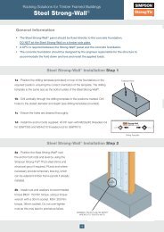
Step 1: Build masonry to the<br />
required level, ensuring any<br />
coursing bricks or blocks are<br />
at least one course below the<br />
supporting block.<br />
Leave the masonry to cure <strong>for</strong><br />
at least three days.<br />
Step 2: Place the Safety Fast<br />
Lite <strong>Masonry</strong> Hanger <strong>for</strong> solid<br />
joists (SFLH) over the inner leaf<br />
of the blockwork, ensuring the<br />
top flanges are fully bearing<br />
onto the top of the supporting<br />
blockwork <strong>and</strong> are also tight<br />
against the front face of the<br />
blockwork.<br />
Step 3: Install the floor joist<br />
into the SFLH, ensuring the gap<br />
between the end of the joist <strong>and</strong><br />
the blockwork is a maximum<br />
of 6mm.<br />
Install the specified joist nails<br />
(see table below).<br />
Step 4: Install the appropriate<br />
restraint strap (see note 1 at<br />
bottom of page), ensuring the<br />
strap is tight against the back<br />
face of the blockwork/hanger<br />
return <strong>and</strong> the side of the floor<br />
joist. Fix with fasteners as<br />
specified in the table below.<br />
SFLH - Safety Fast Lite <strong>Masonry</strong> Hanger <strong>for</strong> Solid Joist Per<strong>for</strong>mance Data<br />
Size Range<br />
Joist Fastener Qty<br />
3.75mm x 30mm Square Twist Nail<br />
Safe Working Loads (kN)<br />
Block Strength<br />
Characteristic Capacity (kN)<br />
Block Strength<br />
Height (mm) Width (mm) Hanger FMS (1) Strap 2.8N/mm2<br />
Solid AAC<br />
3.5N/mm 2<br />
Solid AAC<br />
7.0N/mm 2<br />
Solid DAC<br />
2.8N/mm 2<br />
Solid AAC<br />
3.5N/mm 2<br />
Solid AAC<br />
7.0N/mm 2<br />
Solid DAC<br />
100 - 400 38 -100 2 3 3.9 4.5 4.5 6.8 7.9 7.9<br />
Please note:<br />
1. Appropriate variant from FMS strap range, depending on connection detail - refer to FMS content on page 126.<br />
2. Per<strong>for</strong>mance values are with NO masonry above supporting blockwork.<br />
21
<strong>Masonry</strong> Hangers <strong>for</strong> Solid Joists<br />
SFLH Safety Fast Lite Hanger<br />
SFLH Hanger Sizes<br />
Joist Size<br />
Hanger Dimension (mm)<br />
Model No.<br />
Width Height Height (H) Width (W)<br />
100 SFLH100/38 100<br />
125 SFLH125/38 125<br />
150 SFLH150/38 140<br />
Joist Size<br />
Hanger Dimension (mm)<br />
Model No.<br />
Width Height Height (H) Width (W)<br />
100 SFLH100/91 100<br />
125 SFLH125/91 125<br />
150 SFLH150/91 140<br />
35<br />
175 SFLH175/38 165<br />
200 SFLH200/38 190<br />
38<br />
2 Ply 45<br />
or 91<br />
175 SFLH175/91 165<br />
200 SFLH200/91 190<br />
91<br />
225 SFLH225/38 215<br />
225 SFLH225/91 215<br />
250 SFLH250/38 240<br />
250 SFLH250/91 240<br />
300 SFLH300/38 290<br />
300 SFLH300/91 290<br />
100 SFLH100/47 100<br />
100 SFLH100/100 100<br />
125 SFLH125/47 125<br />
125 SFLH125/100 125<br />
150 SFLH150/47 140<br />
150 SFLH150/100 140<br />
45<br />
175 SFLH175/47 165<br />
200 SFLH200/47 190<br />
47<br />
2 Ply 50<br />
or 97<br />
or 100<br />
175 SFLH175/100 165<br />
200 SFLH200/100 190<br />
100<br />
225 SFLH225/47 215<br />
225 SFLH225/100 215<br />
250 SFLH250/47 240<br />
250 SFLH250/100 240<br />
300 SFLH300/47 290<br />
300 SFLH300/100 290<br />
100 SFLH100/50 100<br />
125 SFLH125/50 125<br />
150 SFLH150/50 140<br />
50<br />
175 SFLH175/50 165<br />
200 SFLH200/50 190<br />
50<br />
225 SFLH225/50 215<br />
250 SFLH250/50 240<br />
300 SFLH300/50 290<br />
100 SFLH100/63 100<br />
125 SFLH125/63 125<br />
150 SFLH150/63 140<br />
63<br />
175 SFLH175/63 165<br />
200 SFLH200/63 190<br />
63<br />
225 SFLH225/63 215<br />
250 SFLH250/63 240<br />
300 SFLH300/63 290<br />
100 SFLH100/75 100<br />
125 SFLH125/75 125<br />
150 SFLH150/75 140<br />
75<br />
175 SFLH175/75 165<br />
200 SFLH200/75 190<br />
75<br />
225 SFLH225/75 215<br />
250 SFLH250/75 240<br />
300 SFLH300/75 290<br />
22
<strong>Masonry</strong> Hangers <strong>for</strong> Solid Joists<br />
SFLH Safety Fast Lite Hanger<br />
For example, total number of blocks per pair of joists (4 hangers) @ 600 c/c:<br />
• 2.8N/mm 2 AAC = 24<br />
• 3.5N/mm 2 AAC = 20<br />
• 7.0N/mm 2 DAC = 16<br />
Note: I-Joist shown above <strong>for</strong> ilustration purposes, SFLH is compatible with solid sawn joists.<br />
About working on the floor prior to the next lift of masonry:<br />
1. The floor decking may be stored on the joists provided the load is<br />
uni<strong>for</strong>mly distributed among several joists <strong>and</strong> does not exceed the<br />
hanger or joist capacities. Refer to joist manufacturer or supplier <strong>for</strong><br />
joist capacity <strong>and</strong> maximum construction loads.<br />
2. The floor decking must be securely attached to each joist be<strong>for</strong>e<br />
additional loads can be placed on the system.<br />
3. Pallets of blocks or other construction material should be placed<br />
onto the scaffolding <strong>and</strong> not directly onto the floor. The materials can<br />
then be evenly distributed around the floor manually, ensuring the<br />
hanger or joist capacities are not exceeded.<br />
23
<strong>Masonry</strong> Hangers <strong>for</strong> Solid Joists<br />
SFJC Safety Fast Joist Cap<br />
The SFJC is an innovative product which enables a<br />
safe, practical <strong>and</strong> robust solution that satisfies the<br />
requirements of ‘Approved Document B & L’ of the<br />
Building Regulations.<br />
The SFJC is designed to be used where timber joists are built into a<br />
masonry external wall <strong>and</strong> eliminates the air leakage problems associated<br />
with shrinkage of timber joists. It also provides resistance to fire <strong>for</strong> up to<br />
60 minutes when gaps are filled in with mineral wool.<br />
• SFJC305/50, SFJC305/100 <strong>and</strong> SFJC225/100 models accomodate a<br />
large range of joists types <strong>and</strong> sizes.<br />
• SFJC225/50 specifically designed <strong>for</strong> 50mm solid sawn joists up to<br />
225mm deep.<br />
• Air leakage around the joist end is eliminated.<br />
• Wide face flanges provide an air tight seal.<br />
Material: Black Polypropylene.<br />
The SFJC does not provide any lateral stability to the joists during<br />
construction phase. It is there<strong>for</strong>e necessary to install temporary bracing<br />
in accordance with the joist manufacturers instructions <strong>and</strong>/or st<strong>and</strong>ard<br />
construction practice, to ensure temporary stability of the floor joists.<br />
• Place floor joist onto wall <strong>and</strong> adjust to ensure correct bearing at each<br />
end.<br />
SFJC225/50: SOLID SAWN JOISTS<br />
SFJC<br />
PATENT GB2392928, GB2393459<br />
Typical SFJC225/50 Installation<br />
• Solid sawn joists up to 50mm wide <strong>and</strong> 225mm high can be installed directly<br />
into the SFJC225/50.<br />
SFJC305/50 SOLID SAWN JOISTS<br />
• Solid sawn joists up to 50mm wide <strong>and</strong> 300mm high can be installed directly<br />
into the SFJC305/50. For narrower joist widths use the wedge cut outs to<br />
pack the joist.<br />
SFJC305/100 & SFJC225/100: SOLID SAWN JOISTS<br />
• Steel joist plates slides into the slots within the SFJC <strong>and</strong> are fixed to the top<br />
<strong>and</strong> bottom of the floor joists.<br />
• Nail in place with 2 No 3.75 x 30mm square twist nails per plate.<br />
Typical SFJC305/100 Installation<br />
• Install horizontal restraint straps at maximum 2m centres<br />
• Nail to the timber joists with 8 No 3.75 x 30 square twist nails.<br />
• Build up masonry between SFJC <strong>and</strong> continue with wall construction.<br />
• Ensure all joints between the masonry <strong>and</strong> SFJC are fully filled with mortar.<br />
• With the SFJC305/50 check the tightness of the wedges once wall is completed.<br />
• If necessary, hammer wedges in tight.<br />
• Also if necessary, fill the void around the joist with mineral wool or exp<strong>and</strong>ing foam.<br />
Model No.<br />
Dimensions (mm)<br />
Solid Sawn Joist Sizes<br />
(mm)<br />
Typical SFJC305/50 Installation<br />
Width Height Width Height<br />
SFJC225/50 50 225 50<br />
SFJC225/100 100 225 100<br />
SFJC305/50 50 305 up to 50<br />
SFJC305/100 100 305 up to 100<br />
up to 225<br />
up to 302<br />
1. 2 No. SFJC Wedges supplied with each SFJC305/50.<br />
2. 2 No. Steel Joist Plates supplied with each SFJC305/100 <strong>and</strong> SFJC225/100.<br />
24
<strong>Masonry</strong> Hangers <strong>for</strong> Solid Joists<br />
JHM/HJHM <strong>Masonry</strong> Supported Joist Hangers<br />
JHMs <strong>and</strong> HJHMs are one piece non-welded joist hangers<br />
<strong>for</strong> supporting timber joists, beams <strong>and</strong> trussed rafters from<br />
masonry walls.<br />
JHM<br />
• Built-in inspection slot at the base of the hanger to aid inspection from the<br />
ground.<br />
• HJHM: Heavy duty masonry hanger <strong>for</strong> higher load carrying capacity.<br />
• Top flange provides widest area in contact with masonry support allowing<br />
superior per<strong>for</strong>mance. Embossments on JHM stiffen top flange <strong>and</strong> holes allow<br />
improved mortar keying.<br />
• JHM side flange on deeper hangers is much higher than traditional style,<br />
providing greatly enhanced resistance to joist rotation.<br />
• Regularised <strong>Timber</strong>: we have added new sizes to our JHM range to suit<br />
regularised timber. Use 47mm or 91mm width hangers <strong>for</strong> this new application.<br />
Material:<br />
JHM <strong>and</strong> HJHM: Pre-galvanised mild steel.<br />
Installation:<br />
• Use all specified fasteners. See "General Notes" (page 12).<br />
• Set hanger back flange tight against block wall when built to desired level, then<br />
continue with additional courses to complete wall height. Joist should be tight<br />
into back of hanger when possible. Maximum gap permitted is 6mm.<br />
• MINIMUM 3 COURSES OF SOLID BLOCK (675MM MASONRY) REQUIRED<br />
ABOVE HANGER WITH MORTAR FULLY CURED BEFORE APPLYING LOAD.<br />
• Do not stack blocks or heavy loads on the joists during construction unless the<br />
joists have additional support to take the full load of the blocks vertically <strong>and</strong><br />
horizontally.<br />
• The JHM joists hangers can be fixed to steel beams by means of power<br />
actuated fasteners.<br />
• The shot-fired pins must be installed by a qualified person in accordance with<br />
the manufacturer’s installation requirements.<br />
HJHM<br />
Options<br />
• Return configuration provides additional support by wrapping around three<br />
sides of the block. Designate “return” <strong>and</strong> length of return dimensions when<br />
ordering.<br />
• RETURN HANGERS DO NOT SATISFY THE REQUIREMENTS FOR LATERAL<br />
RESTRAINT TYPE HANGERS.<br />
• Straddle configuration provides two hangers connected across top of support<br />
enabling exact alignment on both sides of supporting wall. Designate “straddle”<br />
<strong>and</strong> length of straddle dimensions when ordering.<br />
JHM Shot Fired to a Steel Girder<br />
Model No.<br />
Steel Support<br />
Fasteners<br />
Joist Nails<br />
Safe Working<br />
Load (kN)<br />
JHM Shot-fired to steel<br />
JHM 4 - Shot Fired Pins 4 - 3.75 x 30mm 5.17<br />
1. The above Safe Working Loads are based upon product tests using four No. Hilti 12mm X-EDNI steel<br />
pins fired through holes provided in the top flange of the hangers onto 4mm thick steel plate. Other<br />
pins may be used provided similar structural per<strong>for</strong>mance in verified by the pin manufacturer.<br />
2. Pin Head size must be sufficient to prevent pull through during loading.<br />
3. The designer must ensure that the steel support member will support the imposed loads.<br />
4. Install shot-fired pins in accordance with manufacturer’s instructions.<br />
25
<strong>Masonry</strong> Hangers <strong>for</strong> Solid Joists<br />
JHM/HJHM <strong>Masonry</strong> Supported Joist Hangers<br />
JHM HANGERS FOR TIMBER AND TRUSS<br />
HJHM HANGERS FOR TIMBER AND TRUSS<br />
Joist Size<br />
Model No.<br />
Hanger Dimension (mm)<br />
Joist Size<br />
Model No.<br />
Hanger Dimension (mm)<br />
Width Height Width (W)<br />
35<br />
47<br />
50<br />
63<br />
2ply 35 or 75<br />
2ply 44 or 91<br />
2ply 50<br />
or 100<br />
Height<br />
(H)<br />
100 JHM100/38 38 100<br />
125 JHM125/38 38 125<br />
150 JHM150/38 38 140<br />
175 JHM175/38 38 165<br />
200 JHM200/38 38 190<br />
225 JHM225/38 38 215<br />
250 JHM250/38 38 240<br />
100 JHM100/47 47 100<br />
125 JHM125/47 47 125<br />
150 JHM150/47 47 140<br />
175 JHM175/47 47 165<br />
200 JHM200/47 47 190<br />
225 JHM225/47 47 215<br />
250 JHM250/47 47 240<br />
100 JHM100/50 50 100<br />
125 JHM125/50 50 125<br />
150 JHM150/50 50 140<br />
175 JHM175/50 50 165<br />
200 JHM200/50 50 190<br />
225 JHM225/50 50 215<br />
250 JHM250/50 50 240<br />
125 JHM125/63 63 125<br />
150 JHM150/63 63 140<br />
175 JHM175/63 63 165<br />
200 JHM200/63 63 190<br />
225 JHM225/63 63 215<br />
250 JHM250/63 63 240<br />
100 JHM100/75 75 100<br />
125 JHM125/75 75 125<br />
150 JHM150/75 75 140<br />
175 JHM175/75 75 165<br />
200 JHM200/75 75 190<br />
225 JHM225/75 75 215<br />
250 JHM250/75 75 240<br />
100 JHM100/91 91 100<br />
125 JHM125/91 91 125<br />
150 JHM150/91 91 140<br />
175 JHM175/91 91 165<br />
200 JHM200/91 91 190<br />
225 JHM225/91 91 215<br />
250 JHM250/91 91 240<br />
100 JHM100/100 100 100<br />
125 JHM125/100 100 125<br />
150 JHM150/100 100 140<br />
175 JHM175/100 100 165<br />
200 JHM200/100 100 190<br />
225 JHM225/100 100 215<br />
250 JHM250/100 100 240<br />
Width Height Width (W)<br />
2ply 35 or 75<br />
2ply 50 or 100<br />
2ply 63<br />
3ply 50 or 2ply<br />
75<br />
Height<br />
(H)<br />
150 HJHM150/75 75 140<br />
175 HJHM175/75 75 165<br />
200 HJHM200/75 75 190<br />
225 HJHM225/75 75 215<br />
250 HJHM250/75 75 240<br />
300 HJHM300/75 75 290<br />
150 HJHM150/100 100 140<br />
175 HJHM175/100 100 165<br />
200 HJHM200/100 100 190<br />
225 HJHM225/100 100 215<br />
250 HJHM250/100 100 240<br />
300 HJHM300/100 100 290<br />
150 HJHM150/125 125 140<br />
200 HJHM200/125 125 190<br />
225 HJHM225/125 125 215<br />
250 HJHM250/125 125 240<br />
150 HJHM150/150 150 140<br />
200 HJHM200/150 150 190<br />
225 HJHM225/150 150 215<br />
250 HJHM250/150 150 240<br />
3ply 63 225 HJHM225/190 190 215<br />
4ply 50 or 2ply<br />
100<br />
150 HJHM150/200 200 140<br />
200 HJHM200/200 200 190<br />
225 HJHM225/200 200 215<br />
250 HJHM250/200 200 240<br />
3ply 75 225 HJHM225/225 225 215<br />
26
<strong>Masonry</strong> Hangers <strong>for</strong> Solid Joists<br />
JHM/HJHM <strong>Masonry</strong> Supported Joist Hangers<br />
Typical JHM Installation JHMS Straddle Configuration JHMR Return Configuration<br />
JHM HANGERS - LOADS<br />
Model<br />
Joist Fasteners<br />
Safe Working Loads (kN)<br />
Block Strength<br />
Characteristic Capacity (kN)<br />
Block Strength<br />
Qty<br />
Nail<br />
2.8N/mm 2<br />
Solid AAC<br />
3.5N/mm 2<br />
Solid LAC<br />
7N/mm 2<br />
Solid DAC<br />
2.8N/mm 2<br />
Solid AAC<br />
3.5N/mm 2<br />
Solid LAC<br />
7N/mm 2<br />
Solid DAC<br />
JHM (1)(2) 2 3.75x30mm 5.29 6.48 9.37 10.59 12.97 13.98<br />
1. Loads are based upon tests conducted by CERAM Building Technology <strong>and</strong> are determined in accordance with EN 845.<br />
2. Loads apply to masonry blocks with a minimum compressive strength as indicated.<br />
3. The block thickness must be at least the same size as the top flange depth (as shown in relevant illustrations).<br />
4. For straddle hangers the minimum S dimension is 100mm.<br />
5. 3.75 x 30mm refers to a square twist nail (not supplied with hanger).<br />
HJHM HANGERS - LOADS<br />
Size Range<br />
(mm)<br />
Joist Fasteners<br />
Width Height Qty Nail<br />
2.8N/mm 2<br />
Solid AAC<br />
Safe Working Loads (kN)<br />
Block Strength<br />
3.5N/mm 2<br />
Solid LAC<br />
7N/mm 2<br />
Solid DAC<br />
2.8N/mm 2<br />
Solid AAC<br />
Characteristic Capacity (kN)<br />
Block Strength<br />
3.5N/mm 2<br />
Solid LAC<br />
7N/mm 2<br />
Solid DAC<br />
40 - 74 140 - 400 2 3.75 x 30mm 8.01 8.01 15.00 16.02 16.02 30.01<br />
75 - 200 140 - 400 2 3.75 x 30mm 14.84 14.84 15.00 29.67 29.67 30.01<br />
91 - 200 140 - 400 8 4.00 x 90mm 14.84 14.84 20.88 29.67 29.67 41.76<br />
201 - 300 140 - 400 2 3.75 x 30mm 8.15 8.15 16.67 15.11 15.11 33.34<br />
1. Test conducted by CERAM Building Technology in accordance with EN846-4 <strong>and</strong> evaluated in accordance with EN845-1.<br />
2. 3.75 x 30mm refers to square twist nails.<br />
3. Loads apply to solid block with minimum compressive strengths indicated. The block thickness must be at least the same size as the top flange length, as<br />
shown in the illustrations above. For straddle hangers the minimum S dimension is 100mm to achieve published loads, except <strong>for</strong> HJHM hangers which must be<br />
twice the top flange length of a single hanger.<br />
SKEWED JHM HANGERS - LOADS<br />
Model<br />
Qty<br />
Joist Fasteners<br />
Nail<br />
2.8N/mm 2<br />
Solid AAC<br />
Safe Working Loads (kN)<br />
Block Strength<br />
3.5N/mm 2<br />
Solid LAC<br />
7N/mm 2<br />
Solid DAC<br />
1. Maximum width 61mm.<br />
2. Maximum skew 45°.<br />
JHM 4 3.75x30mm 5.05 5.17 5.17<br />
27
<strong>Masonry</strong> Hangers <strong>for</strong> Solid Joists<br />
ICF Insulated Concrete Form Hanger<br />
The ICFLC <strong>and</strong> ICFVL-CW ledger connector system is engineered to solve the challenges of<br />
mounting steel or wood ledgers on insulated concrete walls.<br />
The ledger connector system is easy, quick <strong>and</strong> versatile to use. The per<strong>for</strong>ations in the embedded leg of the ICFLC permit the<br />
concrete to flow around it, anchoring the ICFLC securely within the block. The exposed flange provides a structural surface <strong>for</strong><br />
mounting either a wood or a steel ledger.<br />
25.4<br />
150<br />
57<br />
178<br />
264<br />
182<br />
75<br />
46<br />
Measurements are in mm.<br />
ICFVL-CW<br />
1<br />
Attach interior partition walls<br />
with suitable drill point screws<br />
into ICFLC where needed.<br />
3<br />
Use ICFVL-CW <strong>for</strong> solid sawn timber.<br />
2<br />
Use ICFLC to attach ledger to ICF.<br />
4<br />
Use IUSE hanger <strong>for</strong> I-joist floor system.<br />
1<br />
4<br />
2<br />
3<br />
28
<strong>Masonry</strong> Hangers <strong>for</strong> Solid Joists<br />
ICF Insulated Concrete Form Hanger<br />
General Notes<br />
1. Spacings shown apply to vertical loads only.<br />
2. No load duration increase is allowed.<br />
3. Minimum concrete grade C20/25.<br />
4. Tables shown below address spacing requirements <strong>for</strong> <strong>for</strong>ms<br />
up to 67mm thick. For <strong>for</strong>ms 70mm thick, the allowable<br />
download is 7.3kN. Spacing shall be determined by the project<br />
design professional.<br />
5. Do not splice ledger at ICFLC location.<br />
WARNING: Industry studies show that<br />
hardened fasteners can experience<br />
per<strong>for</strong>mance problems in wet<br />
environments. Accordingly, use this<br />
product in dry, interior applications only.<br />
Max. 70mm<br />
Typical Wood Ledger Installation with ICFLC <strong>and</strong> ICFVL-CW.<br />
SOLID SAWN WOOD LEDGER - ICFLC with ICFVL-CW<br />
Download per ICF connector<br />
(kN)<br />
Maximum<br />
Connector Spacing<br />
8.5 1200<br />
1. Use 8 No. D3 screws (provided).<br />
2. Loads assume a minimum C16 ledger.<br />
STEEL LEDGER - ICFLC 67mm<br />
Download per ICF connector<br />
(kN)<br />
Ledger Thickness (mm)<br />
Connector Spacing<br />
8.5 1.6 350<br />
STEEL LEDGER - ICFLC 70mm<br />
Requires 3 screws<br />
at each location.<br />
Table provides<br />
centre spacing.<br />
Download per ICF connector<br />
(kN)<br />
Ledger Thickness (mm)<br />
Connector Spacing<br />
7.8 1.6 350<br />
1. Minimum steel ledger specification is A-653 SS Grade 50.<br />
2. Use three 1/4-14x3/4”, #3 drill point screws (not provided).<br />
3. Minimum screw shear capacity is 3.3kN.<br />
Typical Steel Ledger Installation with ICFLC<br />
(minimum 1.6mm steel ledger).<br />
29
<strong>Masonry</strong> Hangers <strong>for</strong> I-joist & Metal Web<br />
JHMI/HJHMI <strong>Masonry</strong> Supported I-Joist Hangers<br />
JHMI <strong>and</strong> HJHMI are one piece non-welded joist hangers<br />
<strong>for</strong> supporting timber joists, beams <strong>and</strong> trussed rafters from<br />
masonry walls.<br />
JHMI<br />
• Built-in inspection slot at the base of the hanger to aid inspection from<br />
the ground.<br />
• HJHMI: Heavy duty masonry hanger <strong>for</strong> higher load carrying capacity.<br />
• Top flange provides widest area in contact with masonry support<br />
allowing superior per<strong>for</strong>mance. Embossments on JHMI stiffen top<br />
flange <strong>and</strong> holes allow improved mortar keying.<br />
• Side flange is much higher than traditional style, providing greatly<br />
enhanced resistance to joist rotation.<br />
Material:<br />
JHMI <strong>and</strong> HJHMI: Pre-galvanised mild steel.<br />
Installation:<br />
• Use all specified fasteners. See "General Notes" (page 12).<br />
• Set hanger back flange tight against block wall when built to desired<br />
level, then continue with additional courses to complete wall height.<br />
Joist should be tight into back of hanger when possible. Maximum gap<br />
permitted is 6mm.<br />
• Minimum 3 courses of solid block (675mm masonry) required<br />
above hanger with mortar fully cured be<strong>for</strong>e applying load.<br />
• JHMI hangers have two PAN or obround nail holes located so that<br />
nails can be driven at an angle into the lower chord of an I-joist. Web<br />
stiffeners may be required by the I-joist manufacturer.<br />
• Do not stack blocks or heavy loads on the joists during construction<br />
unless the joists have additional support to take the full load of the<br />
blocks vertically <strong>and</strong> horizontally.<br />
• JHMI range of joists hangers can be fixed to steel beams by means of<br />
powder actuated fasteners.<br />
• The shot-fired pins must be installed by a qualified person in<br />
accordance with the manufacturer’s installation requirements.<br />
HJHMI<br />
Options<br />
• Return configuration provides additional support by wrapping around<br />
three sides of the block. Designate “return” <strong>and</strong> length of return<br />
dimensions when ordering.<br />
• Return hangers do not satisfy the requirements <strong>for</strong> lateral restraint type<br />
hangers.<br />
• Straddle configuration provides two hangers connected across top<br />
of support enabling exact alignment on both sides of supporting wall.<br />
JHMI Shot-fired to steel<br />
JHMI Shot Fired to a Steel Girder<br />
Model No.<br />
Steel Support<br />
Fasteners<br />
Joist Nails<br />
Safe Working<br />
Load (kN)<br />
JHMI 4 - Shot Fired Pins 2 - 3.75 x 30mm 5.17<br />
1. The above Safe Working Loads are based upon product tests using four No. Hilti 12mm X-EDNI steel<br />
pins fired through holes provided in the top flange of the hangers onto 4mm thick steel plate. Other<br />
pins may be used provided similar structural per<strong>for</strong>mance in verified by the pin manufacturer. Pin Head<br />
size must be sufficient to prevent pull through during loading.<br />
2. The designer must ensure that the steel support member will support the imposed loads.<br />
3. Install shot-fired pins in accordance with manufacturers instructions.<br />
30
<strong>Masonry</strong> Hangers <strong>for</strong> I-joist & Metal Web<br />
JHMI/HJHMI <strong>Masonry</strong> Supported I-Joist Hangers<br />
Typical JHMI Installation JHMIS Straddle Configuration JHMIR Return Configuration<br />
JHMI HANGERS FOR ENGINEERED WOOD SIZES - LOADS<br />
Model<br />
Joist Fasteners<br />
Safe Working Loads (kN)<br />
Block Strength<br />
Characteristic Capacity (kN)<br />
Block Strength<br />
Qty<br />
Nail<br />
2.8N/mm 2<br />
Solid AAC<br />
3.5N/mm 2<br />
Solid LAC<br />
7N/mm 2<br />
Solid DAC<br />
2.8N/mm 2<br />
Solid AAC<br />
3.5N/mm 2<br />
Solid LAC<br />
7N/mm 2<br />
Solid DAC<br />
JHMI 2 3.75x30 5.29 6.48 9.37 10.59 12.97 13.98<br />
1. Loads are based upon tests conducted by CERAM Building Technology <strong>and</strong> are determined in accordance with <strong>and</strong> EN 845.<br />
2. Loads apply to masonry blocks with a minimum compressive strength as indicated.<br />
3. The block thickness must be at least the same size as the top flange depth (as shown in relevant illustrations).<br />
4. For straddle hangers the minimum S dimension is 100mm.<br />
5. 3.75 x 30mm refers to a square twist nail (not supplied with hanger).<br />
HJHMI HANGERS FOR ENGINEERED WOOD SIZES - LOADS<br />
Size Range<br />
(mm)<br />
Joist Fasteners<br />
Safe Working Loads (kN)<br />
Characteristic Capacity (kN)<br />
Block Strength<br />
Block Strength<br />
Width<br />
Height<br />
Qty<br />
Nail<br />
2.8N/mm 2<br />
Solid AAC<br />
3.5N/mm 2<br />
Solid LAC<br />
7N/mm 2<br />
Solid DAC<br />
2.8N/mm 2<br />
Solid AAC<br />
3.5N/mm 2<br />
Solid LAC<br />
7N/mm 2<br />
Solid DAC<br />
40 - 74 140 - 400 2 3.75 x 30mm 8.01 8.01 15.00 16.02 16.02 30.01<br />
75 - 200 140 - 400 2 3.75 x 30mm 14.84 14.84 15.00 29.67 29.67 30.01<br />
91 - 200 140 - 400 8 4.00 x 90mm 14.84 14.84 20.88 29.67 29.67 41.76<br />
201 - 300 140 - 400 2 3.75 x 30mm 8.15 8.15 16.67 15.11 15.11 33.34<br />
1. Test conducted by CERAM Building Technology in accordance with EN846-4 <strong>and</strong> evaluated in accordance with EN845-1.<br />
2. 3.75 x 30mm refers to square twist nails.<br />
3. Loads apply to solid block with minimum compressive strengths indicated. The block thickness must be at least the same size as the top flange length, as<br />
shown in the illustrations above. For straddle hangers the minimum S dimension is 100mm to achieve published loads, except <strong>for</strong> HJHM hangers which must<br />
be twice the top flange length of a single hanger.<br />
4. Shading Indicates installation requires web stiffeners when used to support I-joists.<br />
SKEWED JHMI HANGERS - LOADS<br />
Model<br />
Qty<br />
Joist Fasteners<br />
Nail<br />
2.8N/mm 2<br />
Solid AAC<br />
Safe Working Loads (kN)<br />
Block Strength<br />
3.5N/mm 2<br />
Solid LAC<br />
7N/mm 2<br />
Solid DAC<br />
JHMI (1)(2) 4 3.75x30mm 5.05 5.17 5.17<br />
1. Maximum width: 61mm<br />
2. Maximum skew 45 o<br />
Continued On Next Page.<br />
31
<strong>Masonry</strong> Hangers <strong>for</strong> I-joist & Metal Web<br />
JHMI/HJHMI <strong>Masonry</strong> Supported I-Joist Hangers<br />
JHMI Hangers <strong>for</strong> Engineered Wood<br />
Joist Size<br />
Hanger Dimension (mm)<br />
Model No.<br />
Width Height Width (W) Height (H)<br />
HJHMI Hangers <strong>for</strong> Engineered Wood<br />
Hanger<br />
Joist Size<br />
Dimension (mm)<br />
Model No.<br />
Width Height Width (W) Height (H)<br />
Hanger<br />
Joist Size<br />
Dimension (mm)<br />
Model No.<br />
Width Height Width (W) Height (H)<br />
38<br />
45<br />
47<br />
51<br />
58 or 60<br />
63<br />
68<br />
70<br />
72<br />
2ply 38<br />
2ply 45<br />
or 89<br />
2ply 47<br />
97<br />
114 JHMI114/40 40 114<br />
140 JHMI140/40 40 140<br />
184 JHMI184/40 40 184<br />
195 JHMI195/40 40 195<br />
220 JHMI225/40 40 225<br />
240 JHMI240/40 40 240<br />
300 JHMI300/40 40 300<br />
350 JHMI350/40 40 350<br />
145 JHMI145/47 47 145<br />
184 JHMI184/47 47 184<br />
195 JHMI195/47 47 195<br />
200 JHMI200/47 47 200<br />
220 JHMI225/47 47 225<br />
240 JHMI240/47 47 240<br />
300 JHMI300/47 47 300<br />
350 JHMI350/47 47 350<br />
400 JHMI400/47 47 400<br />
145 JHMI145/50 50 145<br />
195 JHMI195/50 50 195<br />
225 JHMI225/50 50 225<br />
235 JHMI235/50 50 235<br />
240 JHMI240/50 50 240<br />
245 JHMI245/50 50 245<br />
300 JHMI300/50 50 300<br />
350 JHMI350/50 50 350<br />
400 JHMI400/50 50 400<br />
225 JHMI225/53 53 225<br />
240 JHMI240/53 53 240<br />
300 JHMI300/53 53 300<br />
350 JHMI350/53 53 350<br />
400 JHMI400/53 53 400<br />
195 JHMI195/61 61 195<br />
200 JHMI200/61 61 200<br />
220 JHMI225/61 61 225<br />
235 JHMI235/61 61 235<br />
240 JHMI240/61 61 240<br />
245 JHMI245/61 61 245<br />
300 JHMI300/61 61 300<br />
350 JHMI350/61 61 350<br />
400 JHMI400/61 61 400<br />
195 JHMI195/66 66 195<br />
220-225 JHMI225/66 66 225<br />
235 JHMI235/66 66 235<br />
240 JHMI240/66 66 240<br />
245 JHMI245/66 66 245<br />
300 JHMI300/66 66 300<br />
350 JHMI350/66 66 350<br />
400 JHMI400/66 66 400<br />
220 JHMI225/70 70 225<br />
240 JHMI240/70 70 240<br />
245 JHMI245/70 70 245<br />
300 JHMI300/70 70 300<br />
350 JHMI350/70 70 350<br />
400 JHMI400/70 70 400<br />
200 JHMI200/72 72 200<br />
220 JHMI225/72 72 225<br />
240 JHMI240/72 72 240<br />
300 JHMI300/72 72 300<br />
350 JHMI350/72 72 350<br />
400 JHMI400/72 72 400<br />
195 JHMI195/75 75 195<br />
220 JHMI225/75 75 225<br />
235 JHMI235/75 75 235<br />
245 JHMI245/75 75 245<br />
300 JHMI300/75 75 300<br />
350 JHMI350/75 75 350<br />
400 JHMI400/75 75 400<br />
114 JHMI114/78 78 114<br />
140 JHMI140/78 78 140<br />
184 JHMI184/78 78 184<br />
220 JHMI225/78 78 225<br />
235 JHMI235/78 78 235<br />
240 JHMI240/78 78 240<br />
300 JHMI300/78 78 300<br />
350 JHMI350/78 78 350<br />
184 JHMI184/91 91 184<br />
195 JHMI195/91 91 195<br />
200 JHMI200/91 91 200<br />
220 JHMI225/91 91 225<br />
235 JHMI235/91 91 235<br />
240 JHMI240/91 91 240<br />
245 JHMI245/91 91 245<br />
300 JHMI300/91 91 300<br />
350 JHMI350/91 91 350<br />
400 JHMI400/91 91 400<br />
195 JHMI195/96 96 195<br />
225 JHMI225/96 96 225<br />
235 JHMI235/96 96 235<br />
240 JHMI240/96 96 240<br />
245 JHMI245/96 96 245<br />
300 JHMI300/96 96 300<br />
350 JHMI350/96 96 350<br />
400 JHMI400/96 96 400<br />
195 JHMI195/100 100 195<br />
220 JHMI225/100 100 225<br />
245 JHMI245/100 100 245<br />
300 JHMI300/100 100 300<br />
350 JHMI350/100 100 350<br />
400 JHMI400/100 100 400<br />
45<br />
47<br />
63<br />
70<br />
72<br />
2ply 38<br />
2ply<br />
45<br />
or 89<br />
2ply 47<br />
97<br />
2ply 51<br />
2ply<br />
58 or 2ply 60<br />
2ply 63<br />
2ply 70<br />
2ply 72<br />
225 HJHMI225/47 47 225<br />
240 HJHMI240/47 47 240<br />
300 HJHMI300/47 47 300<br />
350 HJHMI350/47 47 350<br />
400 HJHMI400/47 47 400<br />
225 HJHMI225/50 50 225<br />
235 HJHMI235/50 50 235<br />
240 HJHMI240/50 50 240<br />
245 HJHMI245/50 50 245<br />
300 HJHMI300/50 50 300<br />
350 HJHMI350/50 50 350<br />
400 HJHMI400/50 50 400<br />
195 HJHMI195/66 66 195<br />
225 HJHMI225/66 66 225<br />
235 HJHMI235/66 66 235<br />
245 HJHMI245/66 66 245<br />
300 HJHMI300/66 66 300<br />
350 HJHMI350/66 66 350<br />
400 HJHMI400/66 66 400<br />
200 HJHMI200/72 72 200<br />
225 HJHMI225/72 72 225<br />
240 HJHMI240/72 72 240<br />
300 HJHMI300/72 72 300<br />
350 HJHMI350/72 72 350<br />
400 HJHMI400/72 72 400<br />
195 HJHMI195/75 75 195<br />
225 HJHMI225/75 75 225<br />
235 HJHMI235/75 75 235<br />
245 HJHMI245/75 75 245<br />
300 HJHMI300/75 75 300<br />
195 HJHMI195/78 78 195<br />
220 HJHMI225/78 78 225<br />
235 HJHMI235/78 78 235<br />
240 HJHMI240/78 78 240<br />
245 HJHMI245/78 78 245<br />
300 HJHMI300/78 78 300<br />
400 HJHMI400/78 78 400<br />
145 HJHMI145/91 91 145<br />
184 HJHMI184/91 91 184<br />
195 HJHMI195/91 91 195<br />
200 HJHMI200/91 91 200<br />
220 HJHMI225/91 91 225<br />
235 HJHMI235/91 91 235<br />
240 HJHMI240/91 91 240<br />
245 HJHMI245/91 91 245<br />
300 HJHMI300/91 91 300<br />
350 HJHMI350/91 91 350<br />
400 HJHMI400/91 91 400<br />
195 HJHMI195/96 96 195<br />
220 HJHMI225/96 96 225<br />
235 HJHMI235/96 96 235<br />
240 HJHMI240/96 96 240<br />
245 HJHMI245/96 96 245<br />
300 HJHMI300/96 96 300<br />
350 HJHMI350/96 96 350<br />
400 HJHMI350/96 96 400<br />
195 HJHMI195/96 85 195<br />
220 HJHMI225/100 100 225<br />
245 HJHMI245/100 100 245<br />
300 HJHMI300/100 100 300<br />
350 HJHMI350/100 100 350<br />
400 HJHMI400/100 100 400<br />
450 HJHMI450/100 100 450<br />
240 HJHMI240/105 105 240<br />
300 HJHMI300/105 105 300<br />
350 HJHMI350/105 105 350<br />
400 HJHMI400/105 105 400<br />
195 HJHMI195/120 120 195<br />
200 HJHMI200/120 120 200<br />
220 HJHMI225/120 120 225<br />
235 HJHMI235/120 120 235<br />
240 HJHMI240/120 120 240<br />
245 HJHMI245/120 120 245<br />
300 HJHMI300/120 120 300<br />
350 HJHMI350/120 120 350<br />
400 HJHMI400/120 120 400<br />
195 HJHMI195/129 129 195<br />
220-225 HJHMI225/129 129 225<br />
240 HJHMI240/129 129 240<br />
300 HJHMI300/129 129 300<br />
400 HJHMI400/129 129 400<br />
225 HJHMI225/142 142 225<br />
240 HJHMI240/142 142 240<br />
300 HJHMI300/142 142 300<br />
350 HJHMI350/142 142 350<br />
400 HJHMI400/142 142 400<br />
195 HJHMI195/146 146 195<br />
220 HJHMI225/146 146 225<br />
235 HJHMI235/146 146 235<br />
245 HJHMI245/146 146 245<br />
300 HJHMI300/146 146 300<br />
350 HJHMI350/146 146 350<br />
400 HJHMI400/146 146 400<br />
4ply<br />
45<br />
or 2ply<br />
90<br />
or 1ply 178<br />
2ply 90<br />
2ply 97<br />
3ply 70<br />
184 HJHMI184/180 180 184<br />
195 HJHMI195/180 180 195<br />
220 HJHMI225/180 180 225<br />
220 HJHMI225/180 180 225<br />
235 HJHMI235/180 180 235<br />
240 HJHMI240/180 180 240<br />
300 HJHMI300/180 180 300<br />
350 HJHMI350/180 180 350<br />
400 HJHMI400/180 180 400<br />
220 HJHMI225/184 184 225<br />
240 HJHMI240/184 184 240<br />
300 HJHMI300/184 184 300<br />
350 HJHMI350/184 184 350<br />
400 HJHMI400/184 184 400<br />
195 HJHMI195/196 196 195<br />
220 HJHMI225/196 196 225<br />
235 HJHMI235/196 196 235<br />
245 HJHMI245/196 196 245<br />
300 HJHMI300/196 196 300<br />
350 HJHMI350/196 196 350<br />
400 HJHMI400/196 196 400<br />
450 HJHMI450/196 196 450<br />
225 HJHMI225/212 212 225<br />
240 HJHMI240/212 212 240<br />
300 HJHMI300/212 212 300<br />
350 HJHMI350/212 212 350<br />
400 HJHMI400/212 212 400<br />
32
<strong>Masonry</strong> Hangers <strong>for</strong> I-joist & Metal Web<br />
SFJC Safety Fast Joist Cap<br />
The SFJC is an innovative <strong>and</strong> unique product which<br />
enables a safe, practical <strong>and</strong> robust solution that<br />
satisfies the requirements of ‘Approved Document B &<br />
L’ of the Building Regulations.<br />
The SFJC is designed to be used where timber joists are built into a<br />
masonry external wall <strong>and</strong> eliminates the air leakage problems associated<br />
with shrinkage of timber joists. It also provides resistance to fire <strong>for</strong> up to<br />
60 minutes when gaps are filled in with mineral wool.<br />
• SFJC305/50, SFJC305/100 <strong>and</strong> SFJC225/100 models accomodate a<br />
large range of joists types <strong>and</strong> sizes.<br />
• Air leakage around the joist end is eliminated.<br />
• Wide face flanges provide an air tight seal.<br />
Material: Black Polypropylene.<br />
The SFJC does not provide any lateral stability to the joists during construction<br />
phase. It is there<strong>for</strong>e necessary to install temporary bracing in<br />
accordance with the joist manufacturers instructions <strong>and</strong>/or st<strong>and</strong>ard<br />
construction practice, to ensure temporary stability of the floor joists.<br />
• Place the I-joist onto wall <strong>and</strong> adjust to ensure correct bearing at each<br />
end.<br />
• Lift the floor joist <strong>and</strong> install SFJC over the end of the joist, ensuring<br />
the SFJC face flanges are tight against the inner face on the masonry<br />
SFJC305/50 & SFJC225/50: I-JOISTS<br />
SFJC<br />
PATENT GB2392928,<br />
GB2393459<br />
Typical SFJC305/100 Installation<br />
• I-joists up to 50mm wide <strong>and</strong> 300mm high can be installed directly into the<br />
SFJC. For narrower joist widths use the wedge cut outs to pack the joist.<br />
• Tap wedges in to secure the joist into the SFJC.<br />
• Partly drive a 3.75x30mm square twist nail into the bottom chord of the joist<br />
in front of the wedge to secure them in place.<br />
SFJC305/100 & SFJC225/100: I-JOISTS<br />
• For use with double I-joists up to 100mm wide.<br />
• Steel joist plates slides into the slots within the SFJC <strong>and</strong> are fixed to the top<br />
<strong>and</strong> bottom of the floor joists.<br />
• Nail in place with 2 No 3.75 x 30mm square twist nails per plate.<br />
• Install horizontal restraint straps at maximum 2m centres<br />
• Nail to the timber joists with 8 No 3.75 x 30 square twist nails.<br />
• Build up masonry between SFJC <strong>and</strong> continue with wall construction.<br />
• Ensure all joints between the masonry <strong>and</strong> SFJC are fully filled with mortar.<br />
• With the SFJC305/50 check the tightness of the wedges once wall is completed.<br />
• If necessary, hammer wedges in tight <strong>and</strong> adjust retaining nail.<br />
• Also if necessary, fill the void around the joist with mineral wool or exp<strong>and</strong>ing foam.<br />
Typical SFJC305/50 Installation<br />
Model No.<br />
SFJC<br />
Dimensions (mm)<br />
Solid Sawn Joist Sizes<br />
(mm)<br />
Width Height Width Height<br />
SFJC225/50 50 225 50<br />
SFJC225/100 100 225 100<br />
SFJC305/50 50 305 up to 50<br />
SFJC305/100 100 305 up to 100<br />
up to 225<br />
up to 302<br />
1. 2 No SFJC Wedges supplied with each SFJC305/50.<br />
2. 2 No Steel Joist Plates supplied with each SFJC305/100 <strong>and</strong> SFJC225/100.<br />
33
<strong>Masonry</strong> Hangers <strong>for</strong> I-joist & Metal Web<br />
SES <strong>Simpson</strong> End Seal<br />
<strong>Simpson</strong> End Seal: One solution <strong>for</strong> air leakage <strong>and</strong> sound transference requirements.<br />
The SES <strong>Simpson</strong> End Seal provides a fast <strong>and</strong> effective solution to reduce air leakage through<br />
‘pocket masonry’ in block walls. Once installed, it removes the need <strong>for</strong> mastic sealant around the<br />
perimeter of joists (subject to good workmanship when mortar keying).<br />
The SES is a cost effective way to help comply with the requirements of Part L (reduced air leakage)<br />
<strong>and</strong> Part E (reduced sound transference).<br />
The SES allows <strong>for</strong> a full 100mm bearing of joist onto masonry walls.<br />
• Air leakage - reduces air leakage without the need <strong>for</strong> mastic sealant.<br />
• Sound - meets the sound requirements of a proprietary joist cap as specified by Appendix A,<br />
Robust Details Part E H<strong>and</strong>book.<br />
• Fire - provides 1 hour of fire resistance (in compliance with Approved Document B).<br />
• Can be used on external <strong>and</strong> party walls.<br />
• Meets the NHBC Technical requirements.<br />
• Secure fixing - provided by 30mm Square Twist Nails.<br />
Step 1: Prepare<br />
block work to<br />
accept floor joists -<br />
no need <strong>for</strong> mortar<br />
on top. Position<br />
floor joists onto<br />
wall (only one joist<br />
shown <strong>for</strong> clarity).<br />
Fit the End Seal to<br />
the end of the joist<br />
as shown. Ensure<br />
that the End Seal<br />
is tight against the<br />
joist end <strong>and</strong> secure<br />
with two 3.75x30<br />
square twist nails.<br />
SES<br />
Step 2: When<br />
preparing a double<br />
joist, repeat<br />
installation step<br />
1 on the second<br />
I-Joist. Apply<br />
mastic sealant to<br />
the inside face<br />
of the End Seal<br />
between the joists<br />
(see diagram) <strong>and</strong><br />
to the top <strong>and</strong><br />
bottom chords of<br />
the I-Joist.<br />
Top Chord<br />
Mastic Sealant<br />
Step 3: Join the<br />
I-joists together,<br />
checking that the<br />
mastic sealant has<br />
been compressed<br />
between the<br />
end seals. It is<br />
recommended that<br />
the I-joists are joined<br />
together using 2 MJC<br />
(multi joist connector),<br />
one on top <strong>and</strong> one<br />
on the bottom of the<br />
I-joist at 200mm from<br />
the bearing point<br />
(SDW screws can be<br />
used as an alternative<br />
to MJC).<br />
Check with I-Joist<br />
manufacturer.<br />
MJC<br />
(optional)<br />
Mastic Sealant<br />
200mm<br />
Step 5: Lay a bed of mortar<br />
onto the top of the blocks<br />
ensuring mortar is laid tight<br />
up against the joist end. Lay<br />
blocks either side of the joist,<br />
ensuring mortar is applied to<br />
the block ends, completely fill<br />
all joints.<br />
Step 4: Apply mortar<br />
to the void between<br />
the top <strong>and</strong> bottom<br />
chords of the I-joist<br />
on both sides of a<br />
single joist <strong>and</strong> to the<br />
outsides of a double<br />
joist, ensuring the<br />
mortar is packed<br />
against the End Seal.<br />
Mortar<br />
Mortar<br />
Lay the next bed of mortar on<br />
top of the blocks. Continue to<br />
build the wall as normal.<br />
34
<strong>Masonry</strong> Hangers <strong>for</strong> I-joist & Metal Web<br />
SES <strong>Simpson</strong> End Seal<br />
END SEAL OPTIONS AVAILABLE<br />
Flange Height<br />
Joist Dimensions (mm)<br />
Item Code<br />
Height Width<br />
39 200 38 SES118/38<br />
39 220 38 SES138/38<br />
39 240 38 SES158/38<br />
39 300 38 SES218/38<br />
39 200 45 SES118/45<br />
28 220 45 SES158/45<br />
39 220 45 SES138/45<br />
39 240 45 SES158/45<br />
28 241 45 SES179/45<br />
39 300 45 SES218/45<br />
28 302 45 SES240/45<br />
39 360 45 SES278/45<br />
39 400 45 SES318/45<br />
45 195 47 SES101/47<br />
45 220 47 SES124/47<br />
45 235 47 SES141/47<br />
45 245 47 SES151/47<br />
45 300 47 SES206/47<br />
28 220 51 SES158/51<br />
28 241 51 SES179/51<br />
28 302 51 SES240/51<br />
28 356 51 SES294/51<br />
39 200 58 SES118/58<br />
39 220 58 SES138/58<br />
39 240 58 SES158/58<br />
39 300 58 SES218/58<br />
39 360 58 SES278/58<br />
39 400 58 SES318/58<br />
38 220 59 SES138/39<br />
38 241 59 SES159/59<br />
28 241 59 SES179/59<br />
38 302 59 SES220/59<br />
28 301 59 SES240/59<br />
38 356 59 SES274/59<br />
28 356 59 SES294/59<br />
38 406 59 SES324/59<br />
END SEAL OPTIONS AVAILABLE<br />
Flange Height<br />
Joist Dimensions (mm)<br />
Item Code<br />
Height Width<br />
45 195 63 SES101/63<br />
45 220 63 SES126/63 SES<br />
45 235 63 SES141/63<br />
38 225 63 SES143/63<br />
45 245 63 SES151/63<br />
38 241 63 SES159/63<br />
45 300 63 SES206/63<br />
38 302 63 SES220/63<br />
38 356 63 SES274/63<br />
38 406 63 SES324/63<br />
39 200 70 SES118/70<br />
39 220 70 SES138/70<br />
39 240 70 SES158/70<br />
39 300 70 SES218/70<br />
39 360 70 SES278/70<br />
39 400 70 SES318/70<br />
45 195 72 SES101/72<br />
45 220 72 SES126/72<br />
45 245 72 SES151/72<br />
45 300 72 SES206/72<br />
45 350 72 SES256/72<br />
45 400 72 SES306/72<br />
39 200 89 SES118/89<br />
38 220 89 SES138/89<br />
39 220 89 SES138/89<br />
38 225 89 SES143/89<br />
39 240 89 SES158/89<br />
38 241 89 SES158/89<br />
39 300 89 SES218/89<br />
38 302 89 SES220/89<br />
38 356 89 SES274/89<br />
39 360 89 SES278/89<br />
39 400 89 SES318/89<br />
38 406 89 SES324/89<br />
45 195 97 SES101/97<br />
45 220 97 SES126/97<br />
45 245 97 SES151/97<br />
45 300 97 SES206/97<br />
45 350 97 SES256/97<br />
45 400 97 SES306/97<br />
45 450 97 SES356/97<br />
35
<strong>Masonry</strong> Hangers <strong>for</strong> I-joist & Metal Web<br />
SFLHI Safety Fast Lite Hanger<br />
The SFLHI is an innovative single piece hanger designed to support timber joists<br />
from masonry walls without the need <strong>for</strong> masonry above the course of blockwork<br />
supporting the hanger.<br />
The SFLHI has been designed to assist in meeting<br />
the air leakage requirements as part of the<br />
Code <strong>for</strong> Sustainable Homes. Since the joist is<br />
supported by a hanger <strong>and</strong> does not penetrate the<br />
inner leaf of blockwork, the potential <strong>for</strong> air leakage<br />
is reduced <strong>and</strong> avoids the time consuming <strong>and</strong><br />
costly mortaring <strong>and</strong> sealing with mastic around<br />
built in joist ends.<br />
This hanger allows construction work to continue<br />
safely just 3 days after the supporting blockwork<br />
has been laid - as opposed to 28 days in the case<br />
of traditional masonry hangers.<br />
NEW!<br />
100mm<br />
The SFLHI is CE marked, meeting<br />
the requirements EN 845-1.<br />
Patent No. EP2064395<br />
H<br />
W<br />
75mm<br />
SFLHI joist hanger used in conjunction with FMS strap.<br />
SFLHI joist hanger used in conjunction with FMSC strap.<br />
Features <strong>and</strong> Benefits<br />
• Avoids joist penetrating blockwork, minimising air<br />
leakage.<br />
• Achieves published per<strong>for</strong>mance values with no<br />
masonry above the supporting course of blockwork.<br />
• Enables the construction of the floor deck prior to the<br />
next lift of masonry.<br />
• Reduces health & safety risks associated with the<br />
use of traditional masonry hangers with no masonry<br />
courses above them.<br />
• Eliminates the need <strong>for</strong> propping to support the joist.<br />
• Web stiffeners are not required with I-Joists to achieve<br />
published per<strong>for</strong>mance values.<br />
• Use FMS strap range with every hanger spaced up to<br />
600mm centres to provide lateral restraint of the floor<br />
joist in accordance with EN845-1.<br />
• CE Approved: meets the requirements of EN845-1<br />
<strong>and</strong> tested in accordance with EN 846-8.<br />
• Material: Z600 zinc coated steel in accordance with<br />
EN10346:2009.<br />
36
<strong>Masonry</strong> Hangers <strong>for</strong> I-joist & Metal Webs<br />
SFLHI Safety Fast Lite Hanger<br />
1 2 3 4<br />
Step 1: Build masonry to the<br />
required level, ensuring any<br />
coursing bricks or blocks are<br />
at least one course below the<br />
supporting block.<br />
Leave the masonry to cure <strong>for</strong><br />
at least three days.<br />
Step 2: Place the Safety Fast<br />
Lite <strong>Masonry</strong> Hanger <strong>for</strong> I-Joists<br />
(SFLHI) over the inner leaf of<br />
the blockwork, ensuring the<br />
top flanges are fully bearing<br />
onto the top of the supporting<br />
blockwork <strong>and</strong> are also tight<br />
against the front face of the<br />
blockwork.<br />
Step 3: Install the floor joist into<br />
the SFLHI, ensuring the gap<br />
between the end of the joist <strong>and</strong><br />
the blockwork is a maximum<br />
of 6mm.<br />
Install the specified joist nails<br />
(see table below).<br />
Step 4: Install the appropriate<br />
restraint strap (see note 1 at<br />
bottom of page), ensuring the<br />
strap is tight against the back<br />
face of the blockwork/hanger<br />
return <strong>and</strong> the side of the floor<br />
joist. Fix with fasteners as<br />
specified in the table below.<br />
About working on the<br />
floor prior to the next lift<br />
of masonry:<br />
1. The floor decking may be stored<br />
on the joists provided the load is<br />
uni<strong>for</strong>mly distributed among several<br />
joists <strong>and</strong> does not exceed the<br />
hanger or joist capacities. Refer<br />
to joist manufacturer or supplier<br />
<strong>for</strong> joist capacity <strong>and</strong> maximum<br />
construction loads.<br />
2. The floor decking must be securely<br />
attached to each joist be<strong>for</strong>e<br />
additional loads can be placed on<br />
the system.<br />
For example, total number of blocks per pair of joists (4 hangers) @ 600 c/c:<br />
• 2.8N/mm 2 AAC = 24<br />
• 3.5N/mm 2 AAC = 20<br />
• 7.0N/mm 2 DAC = 16<br />
3. Pallets of blocks or other<br />
construction material should be<br />
placed onto the scaffolding <strong>and</strong> not<br />
directly onto the floor. The materials<br />
can then be evenly distributed<br />
around the floor manually, ensuring<br />
the hanger or joist capacities are<br />
not exceeded.<br />
SFLHI - Safety Fast Lite <strong>Masonry</strong> Hanger <strong>for</strong> I-Joist Per<strong>for</strong>mance Data<br />
Size Range<br />
Joist Fastener Qty<br />
3.75mm x 30mm Square Twist Nail<br />
Safe Working Loads (kN)<br />
Block Strength<br />
Characteristic Capacity (kN)<br />
Block Strength<br />
Height (mm) Width (mm) Hanger FMS (1) Strap 2.8N/mm2<br />
Solid AAC<br />
3.5N/mm 2<br />
Solid AAC<br />
7.0N/mm 2<br />
Solid DAC<br />
2.8N/mm 2<br />
Solid AAC<br />
3.5N/mm 2<br />
Solid AAC<br />
7.0N/mm 2<br />
Solid DAC<br />
100 - 400 35 -97 2 3 4.5 4.5 4.5 7.9 7.9 7.9<br />
Please note:<br />
1. Appropriate variant from FMS strap range, depending on connection detail - refer to FMS content on page 126.<br />
2. Per<strong>for</strong>mance values are with NO masonry above supporting blockwork.<br />
37
<strong>Masonry</strong> Hangers <strong>for</strong> I-joist & Metal Web<br />
SFLHI Safety Fast Lite Hanger<br />
SFLHI Hanger Sizes<br />
Joist Size<br />
Hanger Dimension (mm)<br />
SFLHI Model No.<br />
Width Height Height (H) Width (W)<br />
200 SFLHI200/40 200<br />
Joist Size<br />
Hanger Dimension (mm)<br />
Model No.<br />
Width Height Height (H) Width (W)<br />
220 SFLHI225/72 225<br />
38<br />
220 SFLHI225/40 225<br />
240 SFLHI240/40 240<br />
300 SFLHI300/40 300<br />
40<br />
70<br />
240 SFLHI240/72 240<br />
300 SFLHI300/72 300<br />
350 SFLHI350/72 350<br />
72<br />
195 SFLHI195/47 195<br />
360 SFLHI360/72 360<br />
200 SFLHI200/47 200<br />
400 SFLHI400/72 400<br />
220 SFLHI225/47 225<br />
220 SFLHI225/75 225<br />
240 SFLHI240/47 240<br />
240 SFLHI240/75 240<br />
45<br />
245 SFLHI245/47 245<br />
47<br />
72<br />
300 SFLHI300/75 300<br />
75<br />
300 SFLHI300/47 300<br />
350 SFLHI350/75 350<br />
350 SFLHI350/47 350<br />
400 SFLHI400/75 400<br />
360 SFLHI360/47 360<br />
200 SFLHI200/78 200<br />
400 SFLHI400/47 400<br />
195 SFLHI195/50 195<br />
2ply 38 or 75<br />
220 SFLHI225/78 225<br />
240 SFLHI240/78 240<br />
78<br />
220 SFLHI225/50 225<br />
300 SFLHI300/78 300<br />
235 SFLHI235/50 235<br />
200 SFLHI200/91 200<br />
47<br />
240 SFLHI240/50 240<br />
245 SFLHI245/50 245<br />
50<br />
220 SFLHI225/91 225<br />
240 SFLHI240/91 240<br />
300 SFLHI300/50 300<br />
89 or 90<br />
300 SFLHI300/91 300<br />
91<br />
350 SFLHI350/50 350<br />
350 SFLHI350/91 350<br />
400 SFLHI400/50 400<br />
360 SFLHI360/91 360<br />
240 SFLHI240/53 240<br />
400 SFLHI400/91 400<br />
51<br />
300 SFLHI300/53 300<br />
53<br />
195 SFLHI195/100 195<br />
350 SFLHI350/53 350<br />
220 SFLHI225/100 225<br />
195 SFLHI195/61 195<br />
235 SFLHI235/100 235<br />
220 SFLHI225/61 225<br />
245 SFLHI245/100 245<br />
235 SFLHI235/61 235<br />
97<br />
254 SFLHI254/100 254<br />
100<br />
240 SFLHI240/61 240<br />
300 SFLHI300/100 300<br />
58 or 60<br />
245 SFLHI245/61 245<br />
61<br />
350 SFLHI350/100 350<br />
300 SFLHI300/61 300<br />
400 SFLHI400/100 400<br />
350 SFLHI350/61 350<br />
450 SFLHI450/100 450<br />
360 SFLHI360/61 360<br />
400 SFLHI400/61 400<br />
195 SFLHI195/66 195<br />
220 SFLHI225/66 220<br />
235 SFLHI235/66 235<br />
63 or 65<br />
240 SFLHI240/66 240<br />
245 SFLHI245/66 245<br />
66<br />
300 SFLHI300/66 300<br />
350 SFLHI350/66 350<br />
400 SFLHI400/66 400<br />
38
<strong>Masonry</strong> Hangers <strong>for</strong> I-joist & Metal Web<br />
SFHI/SFWHI Safety Fast <strong>Masonry</strong> Restraint Hangers<br />
The SFHI Safety Fast Hangers are an innovative range of products that have<br />
been designed to support timber joists, beams <strong>and</strong> trussed rafters from<br />
masonry walls without the need of supporting masonry above the top flange.<br />
• Requires no masonry above the top flange to achieve the published per<strong>for</strong>mance<br />
values.<br />
• Improved vertical <strong>and</strong> lateral load distribution.<br />
• Mini Strap simply hooks onto the hanger.<br />
• Enables the construction of the floor deck prior to the next lift of masonry.<br />
• Reduces Health & Safety risks associated with the use of the traditional masonry<br />
hangers with no masonry above.<br />
• Eliminates the need <strong>for</strong> propping.<br />
• Mini Strap provides lateral restraint capacity in accordance with NHBC guidelines.<br />
• Allows <strong>for</strong> retrofit of lateral restraint straps.<br />
• Web stiffeners are not required with I-joist to achieve the per<strong>for</strong>mance values.<br />
Material:<br />
SFHI: 2.5mm pre-galvanised mild steel.<br />
SFWHI: 2.5mm mild steel<br />
Mini Strap - 1.0mm pre-galvanised mild steel.<br />
100<br />
PATENT NOS.<br />
GB2316103, GB2354267<br />
GB2390380<br />
PATENT EP1200684<br />
SFWHI<br />
SFHI<br />
FINISH: SFWHI: Hot-dip galvanised.<br />
Installation:<br />
• Use all specified nails.<br />
• Build masonry to required level, ensuring any coursing bricks or blocks are at least one<br />
course below the supporting block, <strong>and</strong> leave to cure.<br />
• Place the Safety Fast Restraint Hanger over the inner leaf of blockwork, ensuring the<br />
bearing plate is fully located onto the top of the masonry, sitting tight against the front<br />
face <strong>and</strong> top of the blockwork.<br />
• Sit the floor joists into the masonry hanger <strong>and</strong> ensure all joists are<br />
correctly installed. The joists should be tight into the back of the hanger where<br />
possible. The maximum gap between the back of the hanger <strong>and</strong> the end of the joist is<br />
6mm.<br />
• Clip the Safety Fast Mini Strap onto the restraining hooks on the side of the hanger <strong>and</strong><br />
nail to the side face of the joist with three No. 3.75x30mm square twist nails. INSTALL<br />
ONLY ONE PER HANGER - EITHER SIDE OF THE HANGER.<br />
PATENT NOS.<br />
GB2354267, GB2390380<br />
PATENT EP1200684<br />
General Installation Notes<br />
• The floor decking may be stored on the joists provided the load is uni<strong>for</strong>mly<br />
distributed between the several joists <strong>and</strong> does not exceed the hanger or joist<br />
capacities. Refer to joist manufacturer or supplier <strong>for</strong> joist capacity <strong>and</strong> maximum<br />
construction loads.<br />
• The floor decking must be securely attached to each joist be<strong>for</strong>e additional loads can be<br />
placed on the system.<br />
• Floor decking <strong>and</strong> blockwork is to be cut where necessary to fit around the upst<strong>and</strong><br />
stiffeners.<br />
• Pallets of blocks or other construction materials should be placed onto the<br />
scaffolding <strong>and</strong> NOT directly onto the floor. The materials can then be evenly<br />
distributed around the floor manually, ensuring hanger or joist capacities are not<br />
exceeded.<br />
Mini Strap<br />
(included with the Safety Fast Hanger)<br />
39
<strong>Masonry</strong> Hangers <strong>for</strong> I-joist & Metal Web<br />
SFHI/SFWHI Safety Fast <strong>Masonry</strong> Restraint Hangers<br />
TYPICAL SFHI INSTALLATION<br />
TYPICAL SFWHI INSTALLATION<br />
SFHI/SFWHI HANGER LOADS<br />
Joist Fasteners<br />
Safe Working Loads (kN)<br />
Characteristic Capacity<br />
(kN)<br />
Model No.<br />
Joist Width<br />
Block Strength<br />
Block Strength<br />
SFHI<br />
SFWHI<br />
Hanger MiniStrap 2.8N/mm 2<br />
Qty Nail Qty Nail<br />
Solid AAC<br />
3.5N/mm 2<br />
Solid LAC<br />
7N/mm 2<br />
Solid DAC<br />
3.5N/mm 2<br />
Solid LAC<br />
7N/mm 2<br />
Solid DAC<br />
< 61mm<br />
5.34 6.67 6.67 13.34 13.34<br />
2 3.75 x 30 3 3.75 x 30<br />
>66mm 9.98 12.47 12.47 17.47 17.47<br />
66mm 11.58 14.47 14.47 28.97 28.94<br />
1. Tests conducted by CERAM Building Technology in accordance with EN846-4 <strong>and</strong> evaluated in accordance with EN845-1.<br />
2. Stated loads are achieved without masonry above the hangertop flange.<br />
3. The block thickness must be the same as the top plate width.<br />
4. The lateral capacity when installed with the FMS ministrap exceeds that provided by traditional straps placed at 2m centres.<br />
5. 3.75 x 30 refers to a square twist nail (not supplied with hanger).<br />
40
<strong>Masonry</strong> Hangers <strong>for</strong> I-joist & Metal Web<br />
SFHI/SFWHI Safety Fast <strong>Masonry</strong> Restraint Hangers<br />
SFHI HANGERS SFHWI HANGERS SFHWI HANGERS<br />
Joist Size<br />
Width<br />
38<br />
45<br />
47<br />
51<br />
58<br />
or 60<br />
63<br />
70<br />
72<br />
2ply 38<br />
2ply 45<br />
or 89<br />
2ply 47<br />
97<br />
Height<br />
Model No.<br />
Hanger Dimension<br />
(mm)<br />
Width<br />
(W)<br />
Height<br />
(H)<br />
195 SFHI195/40/100 40 195<br />
200 SFHI200/40/100 40 200<br />
220 SFHI225/40/100 40 225<br />
235 SFHI235/40/100 40 235<br />
240 SFHI240/40/100 40 240<br />
300 SFHI300/40/100 40 300<br />
195 SFHI195/47/100 47 195<br />
200 SFHI200/47/100 47 200<br />
220 SFHI225/47/100 47 225<br />
235 SFHI235/47/100 47 235<br />
240 SFHI240/47/100 47 240<br />
245 SFHI245/47/100 47 245<br />
300 SFHI300/47/100 47 300<br />
195 SFHI195/50/100 50 195<br />
225 SFHI225/50/100 50 225<br />
235 SFHI235/50/100 50 235<br />
240 SFHI240/50/100 50 235<br />
245 SFHI245/50/100 50 245<br />
300 SFHI300/50/100 50 300<br />
240 SFHI240/53/100 53 240<br />
300 SFHI300/53/100 53 300<br />
195 SFHI195/61/100 61 195<br />
200 SFHI200/61/100 61 200<br />
220 SFHI225/61/100 61 225<br />
235 SFHI235/61/100 61 235<br />
240 SFHI240/61/100 61 240<br />
245 SFHI245/61/100 61 245<br />
300 SFHI300/61/100 61 300<br />
195 SFHI195/66/100 66 195<br />
225 SFHI225/66/100 66 225<br />
235 SFHI235/66/100 66 235<br />
240 SFHI240/66/100 66 240<br />
245 SFHI245/66/100 66 245<br />
300 SFHI300/66/100 66 300<br />
220 SFHI225/72/100 72 225<br />
240 SFHI240/72/100 72 240<br />
300 SFHI300/72/100 72 300<br />
195 SFHI195/75/100 75 195<br />
220 SFHI225/75/100 75 220<br />
235 SFHI235/75/100 75 235<br />
245 SFHI245/75/100 75 245<br />
300 SFHI300/75/100 75 300<br />
195 SFHI195/78/100 78 195<br />
200 SFHI200/78/100 78 200<br />
220 SFHI225/78/100 78 225<br />
235 SFHI235/78/100 78 235<br />
240 SFHI240/78/100 78 240<br />
300 SFHI300/78/100 78 300<br />
195 SFHI195/91/100 91 195<br />
200 SFHI200/91/100 91 200<br />
220 SFHI225/91/100 91 225<br />
235 SFHI235/91/100 91 235<br />
240 SFHI240/91/100 91 240<br />
245 SFHI245/91/100 91 245<br />
300 SFHI300/91/100 91 300<br />
220 SFHI225/96/100 96 225<br />
235 SFHI235/96/100 96 235<br />
240 SFHI240/96/100 96 240<br />
245 SFHI245/96/100 96 245<br />
300 SFHI300/96/100 96 300<br />
195 SFHI195/100/100 100 195<br />
220 SFHI225/100/100 100 225<br />
235 SFHI235/100/100 100 235<br />
240 SFHI240/100/100 100 240<br />
245 SFHI245/100/100 100 245<br />
300 SFHI300/100/100 100 300<br />
Joist Size<br />
Width<br />
70<br />
2ply 38<br />
2ply 45<br />
or 90<br />
2ply 47<br />
97<br />
2ply<br />
51<br />
2ply 58<br />
or 60<br />
2ply 63<br />
Height<br />
Model No.<br />
Hanger Dimension<br />
(mm)<br />
Width<br />
(W)<br />
Height<br />
(H)<br />
220 SFWHI225/72/100 72 225<br />
240 SFWHI240/72/100 72 240<br />
300 SFWHI300/72/100 72 300<br />
350 SFWHI350/72/100 72 350<br />
400 SFWHI400/72/100 72 400<br />
195 SFWHI195/78/100 78 195<br />
220 SFWHI225/78/100 78 225<br />
235 SFWHI235/78/100 78 235<br />
240 SFWHI240/78/100 78 240<br />
245 SFWHI245/78/100 78 245<br />
300 SFWHI300/78/100 78 300<br />
350 SFWHI350/78/100 78 350<br />
400 SFWHI400/78/100 78 400<br />
450 SFWHI450/78/100 78 450<br />
195 SFWHI195/91/100 91 195<br />
200 SFWHI200/91/100 91 200<br />
220 SFWHI225/91/100 91 225<br />
235 SFWHI235/91/100 91 235<br />
240 SFWHI240/91/100 91 240<br />
245 SFWHI245/91/100 91 245<br />
300 SFWHI300/91/100 91 300<br />
350 SFWHI350/91/100 91 350<br />
400 SFWHI400/91/100 91 400<br />
450 SFWHI450/91/100 91 450<br />
195 SFWHI195/96/100 96 195<br />
220 SFWHI225/96/100 96 220<br />
235 SFWHI235/96/100 96 235<br />
240 SFWHI240/96/100 96 240<br />
245 SFWHI245/96/100 96 245<br />
300 SFWHI300/96/100 96 300<br />
350 SFWHI350/96/100 96 350<br />
400 SFWHI400/96/100 96 400<br />
195 SFWHI195/100/100 100 195<br />
220 SFWHI225/100/100 100 225<br />
235 SFWHI235/100/100 100 235<br />
245 SFWHI245100/100 100 245<br />
300 SFWHI300/100/100 100 300<br />
350 SFWHI350/100/100 100 350<br />
400 SFWHI400/100/100 100 400<br />
450 SFWHI450/100/100 100 450<br />
240 SFWHI240/105/100 105 240<br />
300 SFWHI300/105/100 105 300<br />
350 SFWHI350/105/100 105 350<br />
195 SFWHI195/120/100 120 195<br />
200 SFWHI200/120/100 120 200<br />
220 SFWHI225/120/100 120 225<br />
235 SFWHI235/120/100 120 235<br />
240 SFWHI240/120/100 120 240<br />
245 SFWHI245/120/100 120 245<br />
300 SFWHI300/120/100 120 300<br />
350 SFWHI350/120/100 120 350<br />
400 SFWHI400/120/100 120 400<br />
195 SFWHI195/129/100 129 195<br />
220-225 SFWHI225/129/100 129 225<br />
235 SFWHI235/129/100 129 235<br />
240 SFWHI240/129/100 129 240<br />
245 SFWHI245/129/100 129 245<br />
300 SFWHI300/129/100 129 300<br />
350 SFWHI350/129/100 129 350<br />
400 SFWHI400/129/100 129 400<br />
Joist Size<br />
Width<br />
3ply 45<br />
or<br />
135<br />
2ply 70<br />
2ply 72<br />
2ply 75<br />
2ply 89<br />
or 178<br />
2ply 90<br />
2ply 97<br />
Height<br />
Model No.<br />
Hanger Dimension<br />
(mm)<br />
Width<br />
(W)<br />
Height<br />
(H)<br />
184 SFWHI184/135/100 135 184<br />
200 SFWHI200/135/100 135 200<br />
220 SFWHI225/135/100 135 225<br />
240 SFWHI240/135/100 135 240<br />
245 SFWHI245/135/100 135 245<br />
300 SFWHI300/135/100 135 300<br />
350 SFWHI350/135/100 135 350<br />
400 SFWHI400/135/100 135 400<br />
450 SFWHI450/135/100 135 450<br />
220 SFWHI225/142/100 142 225<br />
240 SFWHI240/142/100 142 240<br />
300 SFWHI300/142/100 142 300<br />
350 SFWHI350/142/100 142 350<br />
400 SFWHI400/142/100 142 400<br />
195 SFWHI195/146/100 146 195<br />
220 SFWHI225/146/100 146 225<br />
235 SFWHI235/146/100 146 235<br />
245 SFWHI245/146/100 146 245<br />
300 SFWHI300/146/100 146 300<br />
350 SFWHI350/146/100 146 350<br />
400 SFWHI400/146/100 146 400<br />
195 SFWHI195/152/100 152 195<br />
220 SFWHI225/152/100 152 225<br />
235 SFWHI235/152/100 152 235<br />
240 SFWHI240/152/100 152 240<br />
300 SFWHI300/152/100 152 300<br />
350 SFWHI350/152/100 152 350<br />
400 SFWHI400/152/100 152 400<br />
450 SFWHI450/152/100 152 450<br />
195 SFWHI195/180/100 180 195<br />
200 SFWHI200/180/100 180 200<br />
220 SFWHI225/180/100 180 225<br />
235 SFWHI235/180/100 180 235<br />
245 SFWHI240/180/100 180 240<br />
300 SFWHI300/180/100 180 300<br />
350 SFWHI350/180/100 180 350<br />
400 SFWHI400/180/100 180 400<br />
450 SFWHI450/180/100 180 450<br />
220 SFWHI225/184/100 184 225<br />
240 SFWHI240/184/100 184 240<br />
300 SFWHI300/184/100 184 300<br />
350 SFWHI350/184/100 184 350<br />
400 SFWHI400/184/100 184 400<br />
195 SFWHI195/196/100 196 195<br />
220 SFWHI225/196/100 196 225<br />
235 SFWHI235/196/100 196 235<br />
245 SFWHI245/196/100 196 245<br />
300 SFWHI300/196/100 196 300<br />
350 SFWHI350/196/100 196 350<br />
400 SFWHI400/196/100 196 400<br />
450 SFWHI450/196/100 196 450<br />
41
<strong>Timber</strong> Hangers <strong>for</strong> Solid Joists<br />
JHA Joist Hanger with Adjustable Height Strap<br />
ETA-07/0043<br />
JHA’s are a one piece, non-welded, joist hanger <strong>for</strong> supporting<br />
timber joists from timber members.<br />
JHA270<br />
Adjustable Hanger<br />
• A galvanised joist hanger that provides great support with ease of<br />
installation.<br />
• Published per<strong>for</strong>mance values are based upon 3.75mm x 30mm<br />
square twist nails being used throughout.<br />
• Wider strap provides more surface area on the supporting timber <strong>and</strong><br />
allows increased nail spacing, enhancing the per<strong>for</strong>mance of the critical<br />
hanger-to-support part of the connection.<br />
• Minimum <strong>and</strong> maximum nailing schedules are stamped into the strap<br />
providing correct installation in<strong>for</strong>mation <strong>for</strong> site operatives.<br />
• Speed-prong holds the hanger in position to allow easier attachment.<br />
The installer no longer has to try to hold hanger, joist <strong>and</strong> nail with one<br />
h<strong>and</strong> <strong>and</strong> swing a hammer with the other!<br />
• JHA270 range features a location tab which allows easier alignment of<br />
the hanger.<br />
• The model number <strong>and</strong> size is stamped into the seat of the hanger <strong>for</strong><br />
easy identification, even after installation.<br />
• Regularised <strong>Timber</strong>: we have added new sizes to our JHA range to<br />
suit regularised timber. Use 47mm or 91mm width hangers <strong>for</strong> this new<br />
application.<br />
H<br />
C<br />
B<br />
W<br />
JHA450<br />
Adjustable Hanger<br />
Material:<br />
JHA270—0.9mm pre-galvanised mild steel.<br />
JHA450—1.5mm pre-galvanised mild steel.<br />
Installation:<br />
Alternative installation methods are available depending on the availability of<br />
nailing surface.<br />
Maximum Nailing: All nails must be applied according to the table.<br />
H<br />
Minimum Nailing: For a lower installed cost the minimum nailing schedule<br />
can be used when the maximum nailing load capacity is not needed. A<br />
minimum wrap over of 45mm is required.<br />
Loft Conversions (JHA450 Range): For applications where the hanger<br />
extends below the support. Install top, face, <strong>and</strong> joist nails according to<br />
the table. A minimum wrap over of 45mm is required or maximum nailing.<br />
C<br />
Speed<br />
Prongs<br />
Location Tab<br />
(JHA270)<br />
JHA270<br />
Installation<br />
JHA450<br />
Below Support<br />
Installation<br />
B<br />
W<br />
Used to<br />
temporarily<br />
position <strong>and</strong><br />
secure the hanger<br />
<strong>for</strong> easier <strong>and</strong><br />
faster installation.<br />
42
<strong>Timber</strong> Hangers <strong>for</strong> Solid Joists<br />
JHA Joist Hanger with Adjustable Height Strap<br />
ETA-07/0043<br />
JHA270 Specifications<br />
Installation<br />
Method<br />
Wrap Over<br />
Face Fix<br />
Supporting<br />
Member<br />
Depth<br />
125mm<br />
to<br />
200mm<br />
200mm<br />
to<br />
250mm<br />
Supported<br />
Member<br />
Width<br />
Model<br />
No.<br />
Dimensions (mm) [1] Number of Fasteners [2] Safe Working Loads (kN) [4] Characteristic Loads (kN)<br />
W H B C<br />
1 ply 38 JHA270/38 38 241 50 106<br />
Header<br />
Download<br />
Short<br />
Joist<br />
Term Download Uplift<br />
Face Top Long Term Medium<br />
Term<br />
Uplift<br />
4.2 4.8 1.1 10.0 2.1<br />
1 ply 44 JHA270/44 44 238 50 103 4.8 5.5 1.1 11.6 2.1<br />
1 ply 45 JHA270/47 47 248.5 50 102 5.2 5.9 1.1 12.4 2.1<br />
1 ply 50 JHA270/50 50 247 50 100 5.5 6.2 1.1 13.1 2.1<br />
8 4 4<br />
1 ply 63 JHA270/63 63 249 50 114 5.5 6.3 1.1 13.2 2.1<br />
1 ply 75 JHA270/75 75 243 50 108 5.5 6.3 1.1 13.2 2.1<br />
2 ply 45 JHA270/91 91 234 50 100 5.5 6.3 1.1 13.2 2.1<br />
2 ply 50 JHA270/100 100 230 50 95 5.5 6.3 1.1 13.2 2.1<br />
1 ply 38 JHA270/38 38 241 50 106<br />
3.2 3.6 1.1 7.6 2.1<br />
1 ply 44 JHA270/44 44 238 50 103 3.2 3.6 1.1 7.6 2.1<br />
1 ply 45 JHA270/47 47 248.5 50 102 3.2 3.6 1.1 7.6 2.1<br />
1 ply 50 JHA270/50 50 247 50 100 3.2 3.6 1.1 7.6 2.1<br />
20 ~ 4<br />
1 ply 63 JHA270/63 63 249 50 114 3.2 3.6 1.1 7.6 2.1<br />
1 ply 75 JHA270/75 75 243 50 108 3.2 3.6 1.1 7.6 2.1<br />
2 ply 45 JHA270/91 91 234 50 100 3.2 3.6 1.1 7.6 2.1<br />
2 ply 50 JHA270/100 100 230 50 95 3.2 3.6 1.1 7.6 2.1<br />
1. W, H, B & C dimensions are depicted in the illustration on previous page.<br />
2. 3.75 x 30mm square twist nails used throughout.<br />
3. Characteristic <strong>and</strong> Safe Working Loads are based upon timbers with a characteristic density of 310 Kg/m 3 .<br />
4. Published per<strong>for</strong>mance values are not dependent on the location tab being nailed.<br />
JHA450 Specifications<br />
Installation Method<br />
Wrap Over<br />
Face Fix<br />
Supported<br />
Member<br />
Width<br />
Model<br />
No.<br />
Dimensions (mm) [1] Number of Fasteners [2] Safe Working Loads (kN) [4] Characteristic Loads (kN)<br />
W H B C<br />
1 ply 38 JHA450/38 38 481 50 191<br />
Header<br />
Download<br />
Short<br />
Joist<br />
Term Download Uplift<br />
Face Top Long Term Medium<br />
Term<br />
Uplift<br />
4.2 4.8 1.6 10.0 3.13<br />
1 ply 44 JHA450/44 44 478 50 188 4.8 5.5 1.6 11.6 3.13<br />
1 ply 45 JHA450/47 47 477 50 187 5.2 5.9 1.6 12.4 3.13<br />
1 ply 50 JHA450/50 50 475 50 185 5.5 6.3 1.6 13.2 3.13<br />
1 ply 63 JHA450/63 63 469 50 179 5.5 6.3 1.6 13.2 3.13<br />
1 ply 75 JHA450/75 75 463 50 173 8 4 6 5.5 6.3 1.6 13.2 3.13<br />
2 ply 45 JHA450/91 91 455 50 165 5.5 6.3 1.6 13.2 3.13<br />
2 ply 50 JHA450/100 100 450 50 160 5.5 6.3 1.6 13.2 3.13<br />
2 ply 63 JHA450/125 125 453 63 163 5.7 6.5 1.6 13.6 3.13<br />
3 ply 45 JHA450/137 137 447 63 157 5.7 6.5 1.6 13.6 3.13<br />
3 ply 50 JHA450/150 150 440 63 150 5.7 6.5 1.6 13.6 3.13<br />
1 ply 38 JHA450/38 38 481 50 191<br />
4.2 4.8 1.6 10.0 3.13<br />
1 ply 44 JHA450/44 44 478 50 188 4.4 5.1 1.6 10.6 3.13<br />
1 ply 45 JHA450/47 47 477 50 187 4.4 5.1 1.6 10.6 3.13<br />
1 ply 50 JHA450/50 50 475 50 185 4.4 5.1 1.6 10.6 3.13<br />
1 ply 63 JHA450/63 63 469 50 179 4.4 5.1 1.6 10.6 3.13<br />
1 ply 75 JHA450/75 75 463 50 173 20 ~ 6 4.4 5.1 1.6 10.6 3.13<br />
2 ply 45 JHA450/91 91 455 50 165 4.4 5.1 1.6 10.6 3.13<br />
2 ply 50 JHA450/100 100 450 50 160 4.4 5.1 1.6 10.6 3.13<br />
2 ply 63 JHA450/125 125 453 63 163 4.8 5.5 1.6 11.6 3.13<br />
3 ply 45 JHA450/137 137 447 63 157 4.8 5.5 1.6 11.6 3.13<br />
3 ply 50 JHA450/150 150 440 63 150 4.8 5.5 1.6 11.6 3.13<br />
Loft Conversion<br />
1 ply 38 JHA450/38 38 481 50 191<br />
4.0 4.6 - 9.6 -<br />
1 ply 44 JHA450/44 44 478 50 188 4.0 4.6 - 9.6 -<br />
1 ply 45 JHA450/47 47 477 50 187 4.0 4.6 - 9.6 -<br />
1 ply 50 JHA450/50 50 475 50 185 4.0 4.6 - 9.7 -<br />
1 ply 63 JHA450/63 63 469 50 179 4.1 4.6 - 9.8 -<br />
1 ply 75 JHA450/75 75 463 50 173 4 4 6 4.1 4.6 - 9.8 -<br />
2 ply 45 JHA450/91 91 455 50 165 4.1 4.6 - 9.8 -<br />
2 ply 50 JHA450/100 100 450 50 160 4.1 4.6 - 9.8 -<br />
2 ply 63 JHA450/125 125 453 63 163 4.2 4.8 - 10.1 -<br />
3 ply 45 JHA450/137 137 447 63 157 4.2 4.8 - 10.1 -<br />
3 ply 50 JHA450/150 150 440 63 150 4.2 4.8 - 10.1 -<br />
1. W, H, B & C dimensions are depicted in the illustration on previous page.<br />
2. 3.75 x 30mm square twist nails used throughout.<br />
3. Characteristic <strong>and</strong> Safe Working Loads are based upon timbers with a characteristic density of 310 Kg/m 3 .<br />
43
<strong>Timber</strong> Hangers <strong>for</strong> Solid Joists<br />
IUC Concealed Flange Face Fix Hanger<br />
ETA-04/0042<br />
IUC is a one piece,<br />
non-welded, face mounted<br />
concealed flange hanger <strong>for</strong> both<br />
I-joists <strong>and</strong> solid timber sections.<br />
I-Joist top flanges are laterally restrained by the side<br />
of the hanger, eliminating the need <strong>for</strong> web stiffeners.<br />
I-Joist manufacturers may require web stiffeners.<br />
Material: 1.2mm pre-galvanised mild steel.<br />
Installation:<br />
Use all specified fasteners (see table below). Verify that<br />
the header can take the fasteners specified in the table.<br />
Web stiffeners are not required with I-Joists when the<br />
top flange is laterally supported by both sides of the<br />
hanger.<br />
H<br />
Options:<br />
These hangers cannot be skewed but will normally<br />
accomodate a skew of 5°.<br />
For concealed flange hangers with widths greater than<br />
91mm see SAI hanger catalogue tables.<br />
Enhanced Uplift Loads: The IUC has optional<br />
triangular holes <strong>for</strong> additional uplift. Properly attached<br />
web stiffeners will be required <strong>for</strong> enhanced uplift.<br />
W<br />
IUC SPECIFICATIONS<br />
Joist<br />
Size(mm)<br />
Dimensions<br />
Width Height<br />
Model<br />
No.<br />
H W B<br />
38<br />
45<br />
47<br />
53<br />
58-60<br />
63<br />
70<br />
72<br />
89-90<br />
145 IUC142/40 142 40 51<br />
195-200 IUC192/40 192 40 51<br />
220-245 IUC217/40 217 40 51<br />
145 IUC142/47 142 47 51<br />
195-200 IUC192/47 192 47 5<br />
220-245 IUC217/47 217 47 51<br />
195 IUC192/50 192 50 51<br />
220-245 IUC217/50 217 50 51<br />
195-200 IUC192/53 192 53 51<br />
220-245 IUC217/53 217 53 51<br />
195-200 IUC192/61 192 61 51<br />
220-245 IUC217/61 217 61 51<br />
195-200 IUC192/66 192 66 51<br />
220-245 IUC217/66 217 66 51<br />
195-200 IUC192/72 192 72 51<br />
220-245 IUC217/72 217 72 51<br />
195-200 IUC192/75 192 75 51<br />
220-245 IUC217/75 217 75 51<br />
195-200 IUC192/91 192 91 51<br />
220-245 IUC217/91 217 91 51<br />
Number of Fasteners<br />
Option 1 use 3.75 x 30mm square twist nails. Option 2 use 3.75 x 75mm nails.<br />
44<br />
Safe<br />
Working Load (kN)<br />
C16 & I-Joist<br />
Header<br />
LVL Header<br />
Characteristic Capacity (kN)<br />
C16 & I-Joist<br />
Header<br />
LVL Header<br />
Face Joist Long Term Long Term Download Download<br />
Opt 1 6 Opt 1 2 2.09 2.44 3.80 8.10<br />
Opt 2 6 Opt 1 2 2.57 2.97 7.86 10.68<br />
Opt 1 10 Opt 1 2 3.48 4.06 7.54 13.50<br />
Opt 2 10 Opt 1 2 4.28 4.95 13.10 17.80<br />
Opt 1 12 Opt 1 2 4.17 4.88 10.00 16.20<br />
Opt 2 12 Opt 1 2 5.13 5.94 15.73 20.74<br />
Opt 1 6 Opt 1 2 2.09 2.44 3.80 8.10<br />
Opt 2 6 Opt 1 2 2.57 2.97 7.86 10.68<br />
Opt 1 10 Opt 1 2 3.48 4.06 7.54 13.50<br />
Opt 2 10 Opt 1 2 4.28 4.95 13.10 17.80<br />
Opt 1 12 Opt 1 2 4.17 4.88 10.00 16.20<br />
Opt 2 12 Opt 1 2 5.13 5.94 15.73 20.74<br />
Opt 1 10 Opt 1 2 3.48 4.06 7.54 13.50<br />
Opt 2 10 Opt 1 2 4.28 4.95 13.10 17.80<br />
Opt 1 12 Opt 1 2 4.17 4.88 10.00 16.20<br />
Opt 2 12 Opt 1 2 5.13 5.94 15.73 20.74<br />
Opt 1 10 Opt 1 2 3.48 4.06 7.54 13.50<br />
Opt 2 10 Opt 1 2 4.28 4.95 13.10 17.80<br />
Opt 1 12 Opt 1 2 4.17 4.88 10.00 16.20<br />
Opt 2 12 Opt 1 2 5.13 5.94 15.73 20.74<br />
Opt 1 10 Opt 1 2 3.48 4.06 7.54 13.50<br />
Opt 2 10 Opt 1 2 4.28 4.95 13.10 17.80<br />
Opt 1 12 Opt 1 2 4.17 4.88 10.00 16.20<br />
Opt 2 12 Opt 1 2 5.13 5.94 15.73 20.74<br />
Opt 1 10 Opt 1 2 3.48 4.06 7.54 13.50<br />
Opt 2 10 Opt 1 2 4.28 4.95 13.10 17.80<br />
Opt 1 12 Opt 1 2 4.17 4.88 10.00 16.20<br />
Opt 2 12 Opt 1 2 5.13 5.94 15.73 20.74<br />
Opt 1 10 Opt 1 2 3.48 4.06 7.54 13.50<br />
Opt 2 10 Opt 1 2 4.28 4.95 13.10 17.80<br />
Opt 1 12 Opt 1 2 4.17 4.88 10.00 16.20<br />
Opt 2 12 Opt 1 2 5.13 5.94 15.73 20.74<br />
Opt 1 10 Opt 1 2 3.48 4.06 7.54 13.50<br />
Opt 2 10 Opt 1 2 4.28 4.95 13.10 17.80<br />
Opt 1 12 Opt 1 2 4.17 4.88 10.00 16.20<br />
Opt 2 12 Opt 1 2 5.13 5.94 15.73 20.74<br />
Opt 1 10 Opt 1 2 3.48 4.06 7.54 13.50<br />
Opt 2 10 Opt 1 2 4.28 4.95 13.10 17.80<br />
Opt 1 12 Opt 1 2 4.17 4.88 10.00 16.20<br />
Opt 2 12 Opt 1 2 5.13 5.94 15.73 20.74
<strong>Timber</strong> Hangers <strong>for</strong> Solid Joists<br />
SDE Width Adjustable Face Fix Hanger<br />
ETA-06/0270<br />
The SDE is a two piece, width adjustable face fix hanger.<br />
The two separate components that make up the SDE system can be<br />
adjusted to suit a range of joist widths between 60mm to 120mm.<br />
Each SDE is supplied as a pair.<br />
Material:<br />
H<br />
• 2mm pre-galvanised mild steel.<br />
Installation:<br />
• Use all fasteners as specified in the table below. Check that the<br />
header can accomodate the fasteners specified. Each SDE piece<br />
must also be nailed through the holes underneath.<br />
B<br />
W<br />
SDE Specification<br />
Model<br />
No.<br />
Dimensions<br />
W H B<br />
Number of<br />
Fasteners<br />
Header<br />
Joist<br />
Safe<br />
Working Load (kN) C24<br />
Download<br />
Long Term<br />
Uplift<br />
Short Term<br />
Characteristic Capacity<br />
(kN)<br />
Download<br />
Uplift<br />
SDE300/30<br />
SDE340/30<br />
SDE380/30<br />
SDE440/30<br />
30 120 84 18 1 14 1 1.30 2.30 3.00 4.50<br />
30 120 84 18 2 14 1 4.00 4.80 9.60 9.60<br />
30 140 84 22 1 16 1 1.60 3.20 3.90 6.30<br />
30 140 84 22 2 16 1 4.80 5.80 11.50 11.50<br />
30 160 84 22 1 16 1 4.80 3.20 11.50 6.30<br />
30 160 84 22 2 16 1 4.80 5.80 11.50 11.50<br />
30 190 84 28 1 20 1 6.00 4.70 14.30 9.40<br />
30 190 84 28 2 20 1 6.00 7.20 14.30 14.30<br />
1. 3.75 x 30mm Square Twist Nail.<br />
2. 4.0 x 100mm Smooth Shank Nail.<br />
3. SWL's are based on characteristic loads <strong>and</strong> global safety factors of 2.4 <strong>for</strong> long term <strong>and</strong> 2.0 <strong>for</strong> short term.<br />
45
<strong>Timber</strong> Hangers <strong>for</strong> Solid Joists<br />
SAE/SAI Face Fix Hangers<br />
ETA-06/0270<br />
SAE <strong>and</strong> SAI ranges are heavy-duty hangers designed <strong>for</strong><br />
Applications requiring additional strength.<br />
• SAE hangers have bolt holes <strong>for</strong> 12mm fasteners into the face.<br />
• SAE <strong>Timber</strong> Bolted capacity to be determined according to the relevant<br />
st<strong>and</strong>ards. Do not exceed the load values given in the Bolt Attachment table.<br />
• SAI hangers are not recommended <strong>for</strong> bolted applications.<br />
• The hanger depth is to be at least 60% of the carried member depth to prevent<br />
rotation, unless additional lateral restraint is added to the top of the carried<br />
member.<br />
40<br />
SAE<br />
Material:<br />
SAE <strong>and</strong> SAI—2.0mm pre-galvanised mild steel.<br />
Installation:<br />
• Use all specified fasteners. Verify that the header can take the required fasteners<br />
specified in the table.<br />
• SAE hangers can be installed by filling all round holes, or all bolt holes, with the<br />
specified fasteners. A combination of the two would not give any increase to the<br />
per<strong>for</strong>mance values.<br />
Options:<br />
• Other widths of the SAE hangers are available to order.<br />
• Slope <strong>and</strong> skew options available <strong>for</strong> all SAE hangers (without bolt holes).<br />
• For special SAE Hangers, the fastener specifications <strong>and</strong> per<strong>for</strong>mance values<br />
may differ from the normal hanger specifications. See SAE Hanger Specials<br />
Table <strong>for</strong> details.<br />
• Skews right or left up to 67.5° <strong>and</strong> slopes up or down up to 45°.<br />
• Hangers with skews greater than 15° may have all joist nailing on the outside<br />
angle.<br />
• For SAE hangers with combined skews <strong>and</strong> slopes the maximum SWL is 80%<br />
of the medium term loads stated within the table.<br />
• Concealed flanges available on some models. See SAI Table <strong>for</strong> Hanger Range.<br />
• Sloped <strong>and</strong> skew options can be manufactured, however these would not<br />
include bolt holes. Please refer to the “SAE Hangers Specials” Table opposite.<br />
H<br />
B<br />
SAI<br />
W<br />
Not suitable <strong>for</strong> bolted<br />
applications.<br />
Typical SAI<br />
Installation on a Post<br />
Typical SAE(X) Sloped Down,<br />
Skewed Right installation (no bolt<br />
holes)<br />
Top View SAE(X) Hanger<br />
Skewed Right (no bolt holes)<br />
ACUTE<br />
SIDE<br />
SPECIFY SKEW<br />
ANGLE<br />
W<br />
46
<strong>Timber</strong> Hangers <strong>for</strong> Solid Joists<br />
SAE/SAI Face Fix Hangers<br />
ETA-06/0270<br />
SAE HANGERS<br />
Joist<br />
Width<br />
(mm)<br />
Model<br />
No.<br />
Dimensions<br />
W H B<br />
47<br />
Number of Fasteners<br />
(Use 3.75mm x 30mm)<br />
Safe<br />
Working Load (kN)<br />
Characteristic<br />
Capacity (kN)<br />
C16 LVL Download<br />
(C24)<br />
Header Joist Long Term Medium Term Long Term Medium Term<br />
SAE380/38 38 171 85 22 12 8.50 9.50 9.30 5.00 8.80<br />
38<br />
SAEL500/38 38 231 84 34 18 13.10 14.70 14.30 16.10 17.20<br />
SAE620/38 38 291 75 40 22 15.40 17.30 16.90 18.90 17.20<br />
SAE380/45 45 168 85 22 12 8.50 9.50 9.30 10.40 8.80<br />
45<br />
SAE500/46 46 227 84 34 18 13.10 14.70 14.30 16.10 17.20<br />
SAE620/45 45 288 75 40 22 15.40 17.30 16.90 18.90 17.20<br />
SAE250/50 50 100 84 12 7 4.60 5.20 5.10 5.70 2.90<br />
47 - 50<br />
SAE380/50 50 165 85 22 12 8.50 9.50 9.30 10.40 8.80<br />
SAE500/50 50 225 85 34 18 13.10 14.70 14.30 16.10 17.20<br />
SAE620/50 50 285 75 40 22 15.40 17.30 16.90 18.90 17.20<br />
SAE380/64 64 159 85 22 12 8.50 9.50 9.30 10.40 8.80<br />
63<br />
SAE500/64 64 219 85 34 18 13.10 14.70 14.30 16.10 17.20<br />
SAE620/64 64 279 75 40 22 15.40 17.30 16.90 18.90 17.20<br />
SAE380/76 76 153 85 22 12 8.50 9.50 9.30 10.40 8.80<br />
75 - 76<br />
SAE500/76 76 213 85 34 18 13.10 14.70 14.30 16.10 17.20<br />
SAE620/76 76 273 75 40 22 15.40 17.30 16.90 18.90 17.20<br />
SAE380/90 90 145 85 22 12 8.50 9.50 9.30 10.40 8.80<br />
2 Ply 44<br />
SAEL500/91 91 205 84 32 16 11.60 13.00 12.60 14.20 17.20<br />
SAE620/91 91 265 85 34 18 13.10 14.70 14.30 16.10 17.20<br />
SAE380/100 100 140 85 22 12 8.50 9.50 9.30 10.40 8.80<br />
100<br />
SAE500/100 100 200 85 34 18 13.10 14.70 14.30 16.10 17.20<br />
SAE620/100 100 260 75 40 22 15.40 17.30 16.90 18.90 17.20<br />
125<br />
SAE500/125 125 188 78 30 16 11.60 13.00 12.60 14.20 17.20<br />
SAE620/125 125 248 75 40 22 15.40 17.30 16.90 18.90 17.20<br />
150<br />
SAEL500/150 150 175 78 32 16 11.60 13.00 12.60 14.20 17.20<br />
SAE620/150 150 235 75 40 22 15.40 17.30 16.90 18.90 17.20<br />
200 SAE590/200 200 195 78 30 20 11.60 13.00 12.60 14.20 17.20<br />
201 - 300 SAE690X 201-300 195 78 30 20 11.60 13.00 12.60 14.20 18.60<br />
SAI HANGERS<br />
Joist<br />
Width<br />
(mm)<br />
SAE HANGERS - BOLT ATTACHMENT<br />
Model<br />
No.<br />
Support 4<br />
Number of<br />
Fasteners<br />
Carried<br />
Member 5<br />
Long<br />
Term<br />
<strong>Timber</strong> Support<br />
Medium<br />
Term<br />
Safe<br />
Working Load (kN)<br />
<strong>Masonry</strong> Support<br />
2.8 N/mm 2 3.5 N/mm 2 7 N/mm 2 20 N/mm 2<br />
SAE380 - All 4 M12 12 6.95 7.94 1.80 2.20 4.00 4.00<br />
SAE500/38-100 6 M12 18 10.10 11.54 3.60 4.40 8.00 16.00<br />
SAE500/125-150 6 M12 18 7.99 9.13 3.60 4.40 8.00 16.00<br />
SAE620/38-100 8 M12 22 13.03 14.89 3.60 4.40 8.00 16.00<br />
SAE620/125-150 8 M12 22 10.86 12.41 3.60 4.40 8.00 16.00<br />
1. Safe working loads apply to bolt attachment only.<br />
2. <strong>Timber</strong> support safe working loads are based upon calculation from BS 5268 Part 2 with grade 4.6 12mm bolts into C16 timber <strong>and</strong> load testing per<strong>for</strong>med at <strong>Simpson</strong> <strong>Strong</strong>-Tie testing facility. <strong>Timber</strong> support safe<br />
working loads apply to a minimum support member thickness of 72mm. Safe working loads <strong>for</strong> smaller support members must be reduced in accordance with BS 5268 Part 2. Bolts are to be installed in accordance with<br />
recommendations within BS 5268: Part 2.<br />
3. <strong>Masonry</strong> support safe working loads are based upon calculation with Rawl R-KF2 <strong>and</strong> 12mm stud anchors. Select <strong>and</strong> install fixings according to manufacturers recommendations. Other manufacturers anchors can be<br />
used. The designer is to check the alternate fixing suitability <strong>and</strong> reduce the safe working load where limited by the fixing. Contact <strong>Simpson</strong> <strong>Strong</strong>-Tie <strong>for</strong> bolt hole locations.<br />
4. M12 Bolts.<br />
5. 3.75mm x 30mm Square Twist Nails<br />
SAE(X) Hanger - SPECIALS TABLE<br />
Model<br />
No.<br />
Model<br />
No.<br />
Dimensions<br />
Dimensions<br />
Number of Fasteners<br />
(Use 3.75mm x 30mm)<br />
W H B<br />
Safe<br />
Working Load (kN)<br />
W H B C16 LVL<br />
Header<br />
Joist<br />
Number of Fasteners<br />
(Use 3.75mm x 30mm)<br />
Header<br />
Characteristic<br />
Capacity (kN)<br />
Download<br />
(C24)<br />
SAI380/100 100 140 85 20 10 7.00 7.60 8.50<br />
100<br />
SAI500/100 100 200 85 28 18 13.10 14.30 16.80<br />
SAI620/100 100 260 75 40 22 15.40 16.90 11.70<br />
125<br />
SAI500/125 125 188 78 30 18 11.60 12.70 16.80<br />
SAI620/125 125 248 75 40 22 15.40 16.90 13.20<br />
150<br />
SAI500/150 150 175 78 32 18 11.60 12.70 14.40<br />
SAI620/150 150 235 75 40 22 15.40 16.90 13.20<br />
200 SAI590/200 200 195 78 32 20 13.10 14.30 10.00<br />
Joist<br />
Safe<br />
Working Load (kN)<br />
Long Term<br />
Download<br />
SAE380X 38 - 100 140 - 175 64 14 6 5.40<br />
SAE500X 38 - 150 175 - 235 64 18 8 7.00<br />
SAE620X 38 - 150 235 - 290 64 28 10 10.80<br />
1. These hangers are based upon Composite Wood style SAE hangers <strong>and</strong> contain round <strong>and</strong> triangular nail holes only. ie. No Bolt Holes.<br />
2. SWL’s are based upon a maximum nailing schedule—all round <strong>and</strong> triangular holes filled.<br />
3. Skews right or left up to 67.5° <strong>and</strong> slopes up or down up to 45°.<br />
4. For combined skew <strong>and</strong> sloped hangers the maximum SWL is 80% of the stated loads.<br />
5. Enables hangers to be manufactured <strong>for</strong> any combination of widths <strong>and</strong> heights listed <strong>for</strong> a model number.<br />
6. To order specify model number, width, height, skew <strong>and</strong>/or slope.eg SAE380/63 Skewed Right at 15° becomes SAE380X, W = 63, H = 159, SKR = 15° (<strong>for</strong> no skewed/sloped options please specify skew = 0° & slope = 0°).
<strong>Timber</strong> Hangers <strong>for</strong> Solid Joists<br />
LUP Light Speed Prong Joist Hanger<br />
ETA-07/0150<br />
LUP’s are a one piece, non-welded, joist hanger <strong>for</strong><br />
supporting timber joists from timber members.<br />
LUP230<br />
22<br />
• Precision <strong>for</strong>med <strong>and</strong> engineered <strong>for</strong> fast installation <strong>and</strong> maximum<br />
loads.<br />
• Speed prongs are curved steel <strong>for</strong> extra strength.<br />
• One hit positions the hanger <strong>for</strong> header nailing.<br />
• Prongs into the joist eliminate the need <strong>for</strong> special short nails to hold<br />
the joist into the hanger.<br />
H<br />
Material:<br />
1.0mm pre-galvanised mild steel.<br />
W<br />
38<br />
Installation:<br />
Use all specified fasteners. See General Notes.<br />
Speed prongs provide instant location of the hanger onto the carrying<br />
beam <strong>and</strong> secures the joist into the hanger. If joist prong is deflected <strong>and</strong><br />
bent on a knot, simply use a 3.75mm x 30mm nail or equal through that<br />
slot.<br />
Typical LUP Installation<br />
Options:<br />
Because these hangers are fully die <strong>for</strong>med they cannot be modified.<br />
Joist<br />
Size<br />
(mm)<br />
Model<br />
No.<br />
Dimensions<br />
W H Support<br />
Number of Fasteners<br />
(Use 3.75mm x 30mm)<br />
Carried<br />
Member<br />
Safe<br />
Working Loads (kN)<br />
Long Term<br />
Download<br />
Characteristic<br />
Capacity (kN)<br />
Download<br />
38 x 100 to 150 LUP230/38 38 96 6 2 Prongs 2.90 4.08<br />
44 x 100 to 150 LUP230/44 44 93 6 2 Prongs 2.90 4.08<br />
47 x 100 to 150 LUP230/47 47 92 6 2 Prongs 2.90 4.08<br />
50 x 100 to 150 LUP230/50 50 90 6 2 Prongs 3.00 4.08<br />
MH Mini Hanger<br />
ETA-07/0150<br />
The MH is a one piece galvanised hanger available in a range of<br />
widths <strong>for</strong> light duty applications such as trimmers <strong>and</strong> ceiling<br />
joists of rectangular section.<br />
• Suitable <strong>for</strong> use with solid headers.<br />
• Tab on seat ensures easy <strong>and</strong> accurate placement with easy bend<br />
feature when not required.<br />
• Fully tested on a range of solid headers.<br />
• See page 11 <strong>for</strong> use in sacrificial joist detail.<br />
H<br />
B<br />
Material: 1.0mm pre-galvanised mild steel.<br />
W<br />
Model<br />
No.<br />
Dimensions<br />
W H B Support<br />
Number of<br />
Fasteners<br />
Carried<br />
Member<br />
C16<br />
Long Term<br />
Download<br />
Safe Working Loads (kN)<br />
TR26<br />
Long Term<br />
Download<br />
All Flange<br />
Type<br />
Uplift<br />
Short Term<br />
Characteristic Capacity (kN)<br />
C16<br />
Download<br />
TR26<br />
Download<br />
All Flange<br />
Type<br />
Uplift Short<br />
Term<br />
MH40 40 55 56 6 1 4 1 2.50 2.80 2.00 3.90 5.00 1.01<br />
MH46 46 52 56 6 1 4 1 2.50 2.80 2.00 3.90 5.00 1.01<br />
MH50 50 50 56 6 1 4 1 2.50 2.80 2.00 3.90 5.00 1.01<br />
1. 3.75mm x 30mm Square Twist Nails.<br />
48
<strong>Timber</strong> Hangers <strong>for</strong> Solid Joists<br />
ET Skewed 45° Hanger<br />
ETA-08/0053<br />
The ET is a one piece non-welded joist<br />
hanger <strong>for</strong> supporting skewed timber<br />
joists from timber members.<br />
This range is tested <strong>and</strong> st<strong>and</strong>ardised with a<br />
45° skew angle left or right.<br />
Material:<br />
W 2<br />
NEW!<br />
A 1<br />
1.5mm pre-galvanised mild steel.<br />
Installation:<br />
Use all specified fasteners. See General Notes.<br />
Verify that the header can take the required<br />
fasteners specified in the table.<br />
H<br />
W 1<br />
B<br />
Joist<br />
Width<br />
(mm)<br />
Model<br />
No.<br />
Dimensions<br />
W 1 W 2 H B A 1<br />
Member<br />
Supporting<br />
Number of<br />
Fasteners<br />
(4,0x35)<br />
Supported Member<br />
Face Side Base<br />
Safe<br />
Working<br />
Load (kN)<br />
Long<br />
Term<br />
Characteristic<br />
Capacity (kN)<br />
Download<br />
38 ET248 59 187 95 65 45 14 3 3 3.60 8.80<br />
47 ET260 67 177 97 55 34 16 5 5 4.40 10.60<br />
2 x 38 ET301 108 218 97 55 34 16 5 11 4.70 11.30<br />
1. 4.0x35 refers to CSA4,0x35 nails (available from <strong>Simpson</strong> <strong>Strong</strong>-Tie).<br />
2. SWL’s are based on characteristic loads <strong>and</strong> a global safety factor of 2.4 <strong>for</strong> long term.<br />
3. Use an LS skewable angle <strong>for</strong> extra stability if the joist heigh exceeds 195mm.<br />
ET248 Installed<br />
(shown as installed ‘left to right’.<br />
Can also be skewed ‘right to left.’)<br />
49
<strong>Timber</strong> Hangers <strong>for</strong> Solid Joists<br />
TU Concealed Beam Hanger<br />
ETA-07/0125<br />
The strength of a steel load-rated connection combines with the natural<br />
beauty of wood in the TU concealed beam hanger. Provides an aesthetically<br />
attractive connection <strong>for</strong> exposed beams.<br />
Material: 3.5mm pre-galvanised mild steel; Dowels-mild steel.<br />
Installation: Use all specified fasteners. See General Notes.<br />
• Pins aligned across the grain may cause splitting if the wood shrinks excessively. Use only<br />
in glulam, composite timber or well dried timber. Verify that the header can take the required<br />
fasteners specified in the table.<br />
• Attach to the supporting beam with 5.0 x 40mm screws (supplied).<br />
• Specify dowel length <strong>and</strong> TU size to fit the application.<br />
• Preparation of carried beam is best done off-site with cutting <strong>and</strong> boring tools.<br />
• Holes in beam should be same diameter as dowel to ensure tight fit.<br />
• Centre the TU within height of carried beam.<br />
• Centre pins within the width of the carried member<br />
• For a sloped installation the TU hanger remains as st<strong>and</strong>ard <strong>and</strong> the timber is cut <strong>and</strong> angled<br />
to suit the slope.<br />
• Recommended <strong>for</strong> internal dry environments.<br />
Options: Contact <strong>Simpson</strong> <strong>Strong</strong>-Tie <strong>for</strong> details of special installation tools.<br />
• The st<strong>and</strong>ard install will leave a 5mm gap between carried <strong>and</strong> supporting beams.<br />
• Pocket installation gives a fully concealed connection. See opposite.<br />
• Skewed installation up to 60°. Sloped installation maximum 45°.<br />
• Options: Skewed TU available. To be factory ordered.<br />
• Additional screws are available to order.<br />
TU20 (other sizes similar)<br />
U.S. Patent 5,062,733<br />
Model<br />
No.<br />
Min.<br />
Joist<br />
Height<br />
Connector<br />
Dimensions<br />
W H B<br />
Header<br />
Screw<br />
Fasteners<br />
Joist Dowels<br />
Qty.<br />
Dia.<br />
Safe Working Loads (kN)<br />
Dowel Embedment Length<br />
(mm)<br />
Characteristic Capacity (kN) Download<br />
Dowel Embedment Length (mm)<br />
60 80 100 120 60 80 100 120 140 160<br />
St<strong>and</strong>ard Installation<br />
TU12 120 40 96 101 6 4 8 2.6 3.6 4.3 n/a 7.8 8.4 9.1 9.5 9.5 9.5<br />
TU16 160 60 134 108 18 3 12 3.4 4.8 6.1 7.5 19.0 19.4 20.1 21.1 22.1 23.2<br />
TU20 200 60 174 108 22 4 12 5.5 7.7 9.8 12.0 27.5 28.0 29.0 30.4 31.8 33.2<br />
TU24 240 60 214 108 26 5 12 8.0 11.1 14.2 17.4 36.1 36.7 38.0 39.7 41.4 43.1<br />
TU28 280 60 254 108 30 6 12 10.7 14.9 19.2 21.5 44.7 45.4 47.0 48.9 50.8 52.6<br />
Skewed Installation<br />
TU12 120 40 96 101 6 4 8 2.5 2.5 2.5 n/a 6.7 7.3 8.0 8.4 8.4 8.4<br />
TU16 160 60 134 108 18 3 12 3.4 4.8 6.1 6.1 15.6 16.0 16.7 17.5 18.4 19.4<br />
TU20 200 60 174 108 22 4 12 5.5 7.7 9.8 9.8 23.5 24.0 25.0 26.3 27.7 29.2<br />
TU24 240 60 214 108 26 5 12 8.0 11.1 13.3 13.3 31.9 32.6 34.0 35.8 37.7 39.7<br />
TU28 280 60 254 108 30 6 12 10.7 14.9 16.3 16.3 40.7 41.6 43.4 45.6 48.1 50.7<br />
Sloped Installation<br />
TU12 160 40 96 101 6 4 8 2.3 3.1 3.9 n/a 7.8 8.4 9.1 9.5 9.5 9.5<br />
TU16 190 60 134 108 18 3 12 3.0 4.1 5.3 5.3 18.1 18.5 19.0 19.6 20.2 21.0<br />
TU20 225 60 174 108 22 4 12 4.8 6.7 8.5 8.5 26.3 26.9 27.6 28.5 29.4 30.4<br />
TU24 260 60 214 108 26 5 12 6.9 9.6 12.3 12.3 34.8 25.6 36.4 37.6 38.8 40.0<br />
TU28 295 60 254 108 30 6 12 9.3 12.9 16.6 16.6 43.3 44.2 45.3 46.7 48.1 49.5<br />
Skewed <strong>and</strong> Sloped Installation<br />
TU12 160 40 96 101 6 4 8 2.3 2.5 2.5 n/a 6.5 6.9 7.3 7.9 8.2 8.2<br />
TU16 190 60 134 108 18 3 12 3.0 4.1 5.3 5.3 16.3 16.6 17.0 17.5 18.4 19.1<br />
TU20 225 60 174 108 22 4 12 4.8 6.7 8.5 8.5 24.3 24.8 25.4 26.1 27.4 28.5<br />
TU24 260 60 214 108 26 5 12 6.9 9.6 12.3 12.3 32.9 33.6 34.4 35.5 27.1 38.5<br />
TU28 295 60 254 108 30 6 12 9.3 12.9 16.3 16.3 42.0 42.9 43.9 45.3 47.1 48.9<br />
50
<strong>Timber</strong> Hangers <strong>for</strong> Solid Joists<br />
TU Concealed Beam Hanger<br />
ETA-07/0125<br />
Lateral Capacitites (St<strong>and</strong>ard Installation Only)<br />
Model<br />
No.<br />
Min.<br />
Joist<br />
Height<br />
Connector<br />
Dimensions<br />
W H B<br />
Header<br />
Screw<br />
Fasteners<br />
Joist Dowels<br />
Qty.<br />
Dia.<br />
Safe Working Loads (kN)<br />
Dowel Embedment Length (mm)<br />
Characteristic Capacity (kN) Lateral<br />
Dowel Embedment Length (mm)<br />
60 80 100 120 140 160 60 80 100 120 140 160<br />
TU12 120 40 96 101 6 4 8 0.6 0.8 1.0 1.2 1.2 1.2 1.5 2.0 2.5 3.0 3.0 3.0<br />
TU16 160 60 134 108 18 3 12 0.8 1.1 1.4 1.6 1.6 1.6 2.0 2.6 3.3 4.0 4.0 4.0<br />
TU20 200 60 174 108 22 4 12 1.1 1.5 1.8 2.1 2.1 2.1 2.7 3.5 4.4 5.1 5.1 5.1<br />
TU24 240 60 214 108 26 5 12 1.4 1.8 2.2 2.7 2.7 2.7 3.4 4.4 5.3 6.4 6.4 6.4<br />
TU28 280 60 254 108 30 6 12 1.8 2.2 2.7 3.2 3.2 3.2 4.3 5.3 6.4 7.7 7.7 7.7<br />
Beam-to-Post<br />
Beam-to-Beam<br />
Skewed<br />
Beam-to-Beam<br />
Sloped<br />
Beam-to-Beam<br />
Sloped<br />
Beam-to-Beam<br />
Skew Angle<br />
Installation Procedure <strong>for</strong> a concealed Connector:<br />
Attach connector to header: Position the connector at the pre-determined height <strong>and</strong> screw the connector to the<br />
header or post. Fill all holes with screws supplied.<br />
Prepare the beam: Cut the beam to the length specified. Cut a slot into the end of the beam. Slot width <strong>for</strong> TU12<br />
is 6mm <strong>and</strong> 9mm <strong>for</strong> all others. Cut the slot 3mm deeper than the TU <strong>and</strong> short of the beam height <strong>for</strong> concealed<br />
connector. This allows the connector to be hidden from below. Otherwise cut the slot 3mm deeper than the TU <strong>and</strong><br />
through the entire beam height. Fully Concealed Only: Rout a pocket into the beam end. The pocket should be 6mm<br />
deep. Enough to hide the thickness of the TU <strong>and</strong> the screw heads. This eliminates the gap between the beam &<br />
header (see Pocket Installation Illustration).<br />
Drill beam dowel holes: Position drill guide to provide the proper dowel end distance & height. Clamp in place (Drill<br />
guide available from <strong>Simpson</strong> <strong>Strong</strong>-Tie). Drill the dowel holes to the required diameter. Dowel hole diameter <strong>for</strong> the<br />
TU12 is 8mm <strong>and</strong> 12mm <strong>for</strong> all others.<br />
Install beams: Install top dowel into the carried beam first. Slip beam into place <strong>and</strong> install the remaining dowels<br />
working from the top downwards. Fully Concealed Only: To hide exposed dowel holes when the installation is<br />
complete, glue <strong>and</strong> plug the holes.<br />
St<strong>and</strong>ard Installation<br />
Pocket (Concealed) Installation<br />
TU<br />
51
<strong>Timber</strong> Hangers <strong>for</strong> I-joist <strong>and</strong> Metal Web<br />
ITB/HITB I-Joist Hangers<br />
The ITB/HITB is an innovative new hanger that eliminates the<br />
requirement <strong>for</strong> backer blocks when supported from an I-joist header.<br />
The bottom flange location tabs <strong>and</strong> an open top flange provide enhanced<br />
capacity <strong>and</strong> improved ease of installation.<br />
• Eliminates the need <strong>for</strong> backer blocks with an I-joist to I-joist connection.<br />
• Bottom flange location tabs quickly set the hanger onto the I-joist header.<br />
• Open top flange improves ease-of-installation.<br />
• Only one size of nail required - 3.75mm x 30mm Square Twist.<br />
• Optional nail holes <strong>for</strong> additional download <strong>and</strong> uplift capacity.<br />
H<br />
ETA-04/0042<br />
ITB<br />
OPEN TOP<br />
FLANGE<br />
TO EASE<br />
INSTALLATION<br />
TRIANGULAR<br />
OPTIONAL<br />
NAIL HOLES<br />
FOR ADDITIONAL<br />
UPLIFT<br />
Material:<br />
ITB: 1.2mm pre-galvanised mild steel.<br />
HITB: 2.0mm pre-galvanised mild steel.<br />
ITB Installation:<br />
• St<strong>and</strong>ard Installation (I-joist headers without backer blocks), position the<br />
ITB hanger onto the face of supporting I-joist, ensuring the bottom flanges<br />
are tight up against the underside of the bottom chord <strong>and</strong> fill all round <strong>and</strong><br />
obround holes with the specified nails, starting with the bottom face nails <strong>and</strong><br />
ensuring the hanger sides are vertical be<strong>for</strong>e fixing the top nails.<br />
• Sit the carried joist into the ITB Hanger <strong>and</strong> install the specified nails through<br />
the angled pan nail holes into the joist.<br />
• Enhanced Installation (I-joist headers with backer blocks installed) it is<br />
necessary to fit backer blocks into the web of the I-joist header, ensuring they<br />
are tight to the underside of the top chord. All round, obround <strong>and</strong> triangular<br />
holes are then to be filled with the specified nails, starting with the bottom face<br />
nails <strong>and</strong> ensuring the hanger sides are vertical be<strong>for</strong>e fixing the top nails.<br />
• Enhanced Uplift (I-joists or solid joists with additional joist nails) fit web<br />
stiffeners onto the carried joist <strong>and</strong> fill all joist triangular nail holes with<br />
specified nails.<br />
• When required, backer blocks <strong>and</strong> web stiffeners are to be installed in<br />
accordance with manufacturer’s recommendations.<br />
BOTTOM<br />
FLANGES<br />
50<br />
W<br />
PAN NAIL HOLES<br />
Patent: GB2400384<br />
HITB/-LT<br />
Patent: GB2400384<br />
HITB Installation:<br />
• Designed <strong>for</strong> use with multiple headers.<br />
• Use 3.75mm x 30mm square twist nails during this installation.<br />
• Ensure the supporting I-joists are connected together in accordance with the<br />
manufacturer’s recommended connection methods, i.e. MJC <strong>Connectors</strong>, or<br />
filler blocks.<br />
• Position the HITB hanger onto the face of the supporting I-joists, ensuring the<br />
bottom flanges are tight up against the underside of the bottom chord.<br />
• Fill all face round <strong>and</strong> obround holes with nails. Install nails into the holes<br />
within the bottom flanges.<br />
• Flatten the hanger’s open flanges to the top chords of the supporting I-joist<br />
<strong>and</strong> install a minimum of 4 nails per flange, 2 to the front <strong>and</strong> 2 to the rear of<br />
the joists.<br />
• Bend the bottom chord tabs over the top face of the bottom chord <strong>and</strong> install<br />
nails through the obround holes into the the top face of the bottom chord.<br />
• Sit the carried joist into the HITB hanger <strong>and</strong> install the nails through the round<br />
<strong>and</strong> obround holes into the joist.<br />
• Web stiffeners required with HITB <strong>and</strong> HITB-LT.<br />
Typical ITB<br />
Installation<br />
Typical HITB<br />
Installation<br />
52
<strong>Timber</strong> Hangers <strong>for</strong> I-joist <strong>and</strong> Metal Web<br />
ITB/HITB I-Joist Hangers<br />
ETA-04/0042<br />
ITB Hangers <strong>for</strong> <strong>Timber</strong> I-Joists<br />
HITB Hangers <strong>Timber</strong> I-Joists<br />
With Solid Sawn Flanges<br />
HITB Hangers <strong>Timber</strong> I-Joists<br />
With Solid Sawn Flanges (Cont’d)<br />
Joist<br />
Width<br />
(mm)<br />
Model No.<br />
Dimension (mm)<br />
Height (H)<br />
Width (W)<br />
Joist<br />
Width<br />
(mm)<br />
Model No.<br />
Dimension (mm)<br />
Height (H)<br />
Width (W)<br />
Joist<br />
Width<br />
(mm)<br />
Model No.<br />
Dimension (mm)<br />
Height (H)<br />
Width (W)<br />
38<br />
45<br />
47<br />
51<br />
58-60<br />
63<br />
70<br />
72<br />
2ply 38<br />
2ply 45<br />
or<br />
89-90<br />
2ply 47<br />
ITB195/40 195 40<br />
ITB200/40 200 40<br />
ITB220/40 220 40<br />
ITB240/40 240 40<br />
ITB300/40 300 40<br />
ITB145/47 145 47<br />
ITB195/47 195 47<br />
ITB200/47 200 47<br />
ITB220/47 220 47<br />
ITB240/47 240 47<br />
ITB245/47 245 47<br />
ITB300/47 300 47<br />
ITB195/50 195 50<br />
ITB220/50 220 50<br />
ITB235/50 235 50<br />
ITB240/50 240 50<br />
ITB245/50 245 50<br />
ITB300/50 300 50<br />
ITB220/53 220 53<br />
ITB240/53 240 53<br />
ITB300/53 300 53<br />
ITB195/61 195 61<br />
ITB200/61 200 61<br />
ITB220/61 220 61<br />
ITB240/61 240 61<br />
ITB245/61 245 61<br />
ITB300/61 300 61<br />
ITB195/66 195 66<br />
ITB220/66 220 66<br />
ITB225/66 225 66<br />
ITB235/66 235 66<br />
ITB240/66 240 66<br />
ITB245/66 245 66<br />
ITB300/66 300 66<br />
ITB200/72 200 72<br />
ITB220/72 220 72<br />
ITB240/72 240 72<br />
ITB300/72 300 72<br />
ITB195/75 195 75<br />
ITB220/75 220 75<br />
ITB245/75 245 75<br />
ITB300/75 300 75<br />
ITB195/78 195 78<br />
ITB200/78 200 78<br />
ITB220/78 220 78<br />
ITB240/78 240 78<br />
ITB300/78 300 78<br />
ITB195/91 195 91<br />
ITB200/91 200 91<br />
ITB220/91 220 91<br />
ITB225/91 225 91<br />
ITB240/91 240 91<br />
ITB245/91 245 91<br />
ITB300/91 300 91<br />
ITB195/96 195 96<br />
ITB220/96 220 96<br />
ITB235/96 235 96<br />
ITB240/96 240 96<br />
ITB245/96 245 96<br />
ITB300/96 300 96<br />
45<br />
47<br />
60<br />
63<br />
70<br />
72<br />
89<br />
2ply 47<br />
97<br />
HITB-LT195/47 195 47<br />
HITB-LT200/47 200 47<br />
HITB-LT220/47 220 47<br />
HITB-LT235/47 235 47<br />
HITB-LT240/47 240 47<br />
HITB-LT245/47 245 47<br />
HITB-LT300/47 300 47<br />
HITB-LT195/50 195 50<br />
HITB-LT220/50 220 50<br />
HITB-LT235/50 235 50<br />
HITB-LT240/50 240 50<br />
HITB-LT245/50 245 50<br />
HITB-LT300/50 300 50<br />
HITB-LT195/61 195 61<br />
HITB-LT200/61 200 61<br />
HITB-LT220/61 220 61<br />
HITB-LT235/61 235 61<br />
HITB-LT240/61 240 61<br />
HITB-LT245/61 245 61<br />
HITB-LT300/61 300 61<br />
HITB-LT195/66 195 66<br />
HITB-LT220/66 220 66<br />
HITB-LT235/66 235 66<br />
HITB-LT245/66 245 66<br />
HITB-LT300/66 300 66<br />
HITB-LT220/72 220 72<br />
HITB-LT240/72 240 72<br />
HITB-LT300/72 300 72<br />
HITB-LT195/75 195 75<br />
HITB-LT220/75 220 75<br />
HITB-LT235/75 235 75<br />
HITB-LT245/75 245 75<br />
HITB-LT300/75 300 75<br />
HITB-LT195/91 195 91<br />
HITB-LT200/91 200 91<br />
HITB-LT220/91 220 91<br />
HITB-LT235/91 235 91<br />
HITB-LT240/91 240 91<br />
HITB-LT245/91 245 91<br />
HITB-LT300/91 300 91<br />
HITB-LT195/96 195 96<br />
HITB-LT220/96 220 96<br />
HITB-LT235/96 235 96<br />
HITB-LT240/96 240 96<br />
HITB-LT245/96 245 96<br />
HITB-LT300/96 300 96<br />
HITB-LT195/100 195 100<br />
HITB-LT220/100 220 100<br />
HITB-LT235/100 235 100<br />
HITB-LT245/100 245 100<br />
HITB-LT300/100 300 100<br />
2 Ply 63<br />
HITB Hangers <strong>Timber</strong> I-Joists<br />
With LVL Flanges<br />
Joist<br />
Width<br />
(mm)<br />
38<br />
45<br />
51<br />
58<br />
63<br />
2ply 38<br />
89<br />
HITB-LT195/128 195 128<br />
HITB-LT220/128 220 128<br />
HITB-LT235/128 235 128<br />
HITB-LT245/128 245 128<br />
HITB-LT300/128 300 128<br />
Model No.<br />
Dimension (mm)<br />
Height (H)<br />
Width (W)<br />
HITB200/40 200 40<br />
HITB220/40 220 40<br />
HITB240/40 240 40<br />
HITB300/40 300 40<br />
HITB200/47 200 47<br />
HITB220/47 220 47<br />
HITB240/47 240 47<br />
HITB300/47 300 47<br />
HITB220/53 220 53<br />
HITB240/53 240 53<br />
HITB300/53 300 53<br />
HITB200/61 200 61<br />
HITB220/61 220 61<br />
HITB240/61 240 61<br />
HITB300/61 300 61<br />
HITB220/66 220 66<br />
HITB225/66 225 66<br />
HITB240/66 240 66<br />
HITB300/66 300 66<br />
HITB200/78 200 78<br />
HITB220/78 220 78<br />
HITB240/78 240 78<br />
HITB300/78 300 78<br />
HITB200/91 200 91<br />
HITB220/91 220 91<br />
HITB225/91 225 91<br />
HITB240/91 240 91<br />
HITB300/91 300 91<br />
2 Ply 63 HITB225/128<br />
53
<strong>Timber</strong> Hangers <strong>for</strong> I-joist <strong>and</strong> Metal Web<br />
ITB/HITB I-Joist Hangers<br />
ETA-04/0042<br />
ITB Per<strong>for</strong>mance Data <strong>for</strong> I-Joist with LVL Flanges less than 35mm height:<br />
Model<br />
No.<br />
ITB (H/W)<br />
ITB (H/W)<br />
Dimensions (mm)<br />
Installation<br />
Number of Fasteners<br />
(Use 3.75mm x 30mm)<br />
Height Width Header Joist<br />
240 Min 53 Min<br />
300 Max 61 Max<br />
240 Min 53 Min<br />
300 Max 61 Max<br />
Safe Working Load (kN)<br />
Long Term<br />
Download<br />
Characteristic<br />
Capacity (kN)<br />
Short Term<br />
Uplift Down Uplift<br />
St<strong>and</strong>ard 12 2 4.00 1.00 10.83 1.06<br />
Enhanced 18 6 8.40 2.98 17.44 9.33<br />
ITB Per<strong>for</strong>mance Data <strong>for</strong> I-Joist with LVL Flanges equal to or greater than 35mm height:<br />
Model<br />
No.<br />
ITB (H/W)<br />
ITB (H/W)<br />
Dimensions (mm)<br />
Installation<br />
Number of Fasteners<br />
(Use 3.75mm x 30mm)<br />
Height Width Header Joist<br />
195 Min 40 Min<br />
300 Max 91 Max<br />
195 Min 40 Min<br />
300 Max 91 Max<br />
Safe Working Load (kN)<br />
Long Term<br />
Download<br />
Characteristic<br />
Capacity (kN)<br />
Short Term<br />
Uplift Down Uplift<br />
St<strong>and</strong>ard 12 2 4.60 1.00 9.15 1.20<br />
Enhanced 18 6 8.40 2.98 17.36 7.61<br />
ITB Per<strong>for</strong>mance Data <strong>for</strong> I-Joist with minimum of C24 Solid Sawn Flanges equal to or greater than 38mm<br />
Model<br />
No.<br />
ITB (H/W)<br />
ITB (H/W)<br />
Dimensions (mm)<br />
Installation<br />
Number of Fasteners<br />
(Use 3.75mm x 30mm)<br />
Height Width Header Joist<br />
195 Min 47 Min<br />
300 Max 100 Max<br />
195 Min 47 Min<br />
300 Max 100 Max<br />
Safe Working Load (kN)<br />
Long Term<br />
Download<br />
Characteristic<br />
Capacity (kN)<br />
Short Term<br />
Uplift Down Uplift<br />
St<strong>and</strong>ard 12 2 3.50 1.00 6.73 1.14<br />
Enhanced 18 6 7.50 2.98 17.92 7.96<br />
HITB Per<strong>for</strong>mance Data <strong>for</strong> I-Joist with LVL Flanges less than 35mm height:<br />
Model<br />
No.<br />
HITB (H/W)<br />
Dimensions (mm)<br />
Number of Fasteners<br />
(Use 3.75mm x 30mm)<br />
Height Width Header Joist<br />
240 Min 53 Min<br />
300 Max 61 Max<br />
Safe Working Load (kN)<br />
Long Term<br />
Download<br />
Characteristic<br />
Capacity (kN)<br />
Short Term<br />
Uplift Down Uplift<br />
22 8 6.50 4.80 15.60 11.43<br />
HITB Per<strong>for</strong>mance Data <strong>for</strong> I-Joist with LVL Flanges equal to or greater than 35mm height:<br />
Model<br />
No.<br />
HITB (H/W)<br />
Dimensions (mm)<br />
Number of Fasteners<br />
(Use 3.75mm x 30mm)<br />
Height Width Header Joist<br />
200 Min 53 Min<br />
300 Max 61 Max<br />
Safe Working Load (kN)<br />
Long Term<br />
Download<br />
Characteristic<br />
Capacity (kN)<br />
Short Term<br />
Uplift Down Uplift<br />
22 8 8.00 3.60 17.50 11.43<br />
HITB-LT Per<strong>for</strong>mance Data <strong>for</strong> I-Joist with minimum of C24 Solid Sawn Flanges equal to or greater than 45mm<br />
Model<br />
No.<br />
HITB-LT (H/W)<br />
Dimensions (mm)<br />
Number of Fasteners<br />
(Use 3.75mm x 30mm)<br />
Height Width Header Joist<br />
195 Min 47 Min<br />
300 Max 128 Max<br />
Safe Working Load (kN)<br />
Long Term<br />
Download<br />
Characteristic<br />
Capacity (kN)<br />
Short Term<br />
Uplift Down Uplift<br />
22 8 8.10 4.60 19.10 11.07<br />
54
<strong>Timber</strong> Hangers <strong>for</strong> I-joist <strong>and</strong> Metal Web<br />
ITBS Backer Free I-Joist Hanger with Adjustable Skew<br />
The revolutionary ITBS reduces build cost, confusion, speed of<br />
installation <strong>and</strong> stock holding.<br />
ETA-04/0042<br />
ITBS<br />
The ITBS solves the problem of skew hangers in timber to timber<br />
connections. It can be h<strong>and</strong>ed left or right on site by the carpenter,<br />
removing confusion when the floor is built opposite to the drawing. The<br />
ITBS is also fully adjustable from 5° to 67.5° skew, reducing the need<br />
<strong>for</strong> ‘special’ skew hangers. Finally, the ITBS is a Backer Free hanger<br />
removing the need <strong>for</strong> Backer Blocks in st<strong>and</strong>ard installation. Overall, the<br />
revolutionary ITBS reduces build cost, confusion, speed of installation <strong>and</strong><br />
stock holding.<br />
• St<strong>and</strong>ard 45° skew, with site adjustable skew from 5° to 67.5°.<br />
• Non-h<strong>and</strong>ed hanger, can be left or right skew - adjusted on site,<br />
removing any h<strong>and</strong>ing confusion <strong>and</strong> reducing stock holding.<br />
• Eliminates the need <strong>for</strong> backer blocks when supported from an I-joist<br />
header.<br />
• Open top flange improves ease-of-installation.<br />
• Only one size of nail required - 3.75 x 30mm.<br />
• Can be used on I-joist or Solid Joist headers.<br />
• Optional nail holes <strong>for</strong> additional download.<br />
MATERIAL: 1.5mm thick Mild Steel.<br />
H<br />
W<br />
ITBS Skewable Hanger Sizes<br />
ITBS Skewable Hanger Sizes<br />
Joist<br />
Width<br />
(mm)<br />
Model No.<br />
Height (H)<br />
Dimension (mm)<br />
Width (W)<br />
Joist<br />
Width<br />
(mm)<br />
Model No.<br />
Height (H)<br />
Dimension (mm)<br />
Width (W)<br />
38<br />
45<br />
47<br />
51<br />
58-60<br />
63<br />
ITBS195/40 195 40<br />
ITBS200/40 200 40<br />
ITBS220/40 220 40<br />
ITBS240/40 240 40<br />
ITBS301/40 301 40<br />
ITBS195/47 195 47<br />
ITBS200/47 200 47<br />
ITBS220/47 220 47<br />
ITBS240/47 240 47<br />
ITBS245/47 245 47<br />
ITBS301/47 301 47<br />
ITBS195/50 195 50<br />
ITBS220/50 220 50<br />
ITBS235/50 235 50<br />
ITBS240/50 240 50<br />
ITBS245/50 245 50<br />
ITBS301/50 301 50<br />
ITBS200/53 200 53<br />
ITBS220/53 220 53<br />
ITBS240/53 240 53<br />
ITBS301/53 301 53<br />
ITBS195/61 195 61<br />
ITBS200/61 200 61<br />
ITBS220/61 220 61<br />
ITBS240/61 240 61<br />
ITBS245/61 245 61<br />
ITBS301/61 301 61<br />
ITBS220/66 220 66<br />
ITBS240/66 240 66<br />
ITBS301/66 301 66<br />
70<br />
72<br />
2ply 38<br />
2ply 45<br />
or<br />
89-90<br />
2ply 47<br />
97<br />
ITBS200/72 200 72<br />
ITBS220/72 220 72<br />
ITBS240/72 240 72<br />
ITBS301/72 301 72<br />
ITBS195/75 195 75<br />
ITBS220/75 220 75<br />
ITBS245/75 245 75<br />
ITBS301/75 301 75<br />
ITBS195/78 195 78<br />
ITBS200/78 200 78<br />
ITBS220/78 220 78<br />
ITBS240/78 240 78<br />
ITBS301/78 301 78<br />
ITBS195/91 195 91<br />
ITBS200/91 200 91<br />
ITBS220/91 220 91<br />
ITBS240/91 240 91<br />
ITBS245/91 245 91<br />
ITBS301/91 301 91<br />
ITBS220/96 220 96<br />
ITBS240/96 240 96<br />
ITBS301/96 301 96<br />
ITBS195/100 195 100<br />
ITBS220/100 220 100<br />
ITBS245/100 245 100<br />
ITBS301/100 301 100<br />
55
<strong>Timber</strong> Hangers <strong>for</strong> I-joist <strong>and</strong> Metal Web<br />
ITBS Backer Free I-Joist Hanger with Adjustable Skew<br />
ETA-04/0042<br />
St<strong>and</strong>ard Installation Sequence<br />
Stage 1<br />
Position the back plate<br />
onto the header in<br />
the required position.<br />
Ensure backer blocks<br />
are fitted if enhanced<br />
per<strong>for</strong>mance is required.<br />
Stage 2<br />
Secure the<br />
acute side of the<br />
backplate (inside<br />
angle) with the<br />
specified nails.<br />
Stage 3<br />
Adjust the angle of the<br />
backplate (if different<br />
from 45°) to suit the<br />
required angle. Use<br />
either adjustable set<br />
square or the guide<br />
tables shown below:<br />
Bend one time only.<br />
B<br />
B<br />
A<br />
Stage 4<br />
Secure the obtuse<br />
side of the back<br />
plate onto the<br />
header with all the<br />
specified nails,<br />
ensuring the face<br />
of the back plate<br />
is tight against the<br />
header.<br />
Stage 5<br />
Offer the stirrup to the back<br />
plate ensuring it is located on<br />
the correct side (which can be<br />
either left or right h<strong>and</strong> side).<br />
Once all of the hooks (on the<br />
back plate) are clearly through<br />
the apertures (on the stirrup)<br />
slide in a downward direction<br />
ensuring all hooks engage<br />
onto the stirrup <strong>and</strong> click into<br />
position.<br />
Stage 6<br />
Locate the floor joist into<br />
the stirrup ensuring the<br />
joist is set tight to the<br />
back of the stirrup. The<br />
joist should be secured<br />
into the stirrup with all<br />
specified nails on the<br />
open face of the stirrup.<br />
Angle Guide Table<br />
50mm BACKPLATE<br />
100mm BACKPLATE<br />
Skew Angle<br />
(A)<br />
Distance<br />
(mm) (B)<br />
Skew Angle<br />
(A)<br />
Distance<br />
(mm) B)<br />
5 o 106 5 o 206<br />
15 o 104 15 o 200<br />
22.5 o 100 22.5 o 190<br />
30 o 95 30 o 180<br />
37.5 o 87 37.5 o 166<br />
45 o 79 45 o 149<br />
52.5 o 69 52.5 o 130<br />
60 o 58 60 o 109<br />
67.5 o 46 67.5 o 86<br />
56
<strong>Timber</strong> Hangers <strong>for</strong> I-joist <strong>and</strong> Metal Web<br />
ITBS Backer Free I-Joist Hanger with Adjustable Skew<br />
ETA-04/0042<br />
ITBS Per<strong>for</strong>mance Data <strong>for</strong> I-Joist with LVL Flanges less than 35mm height:<br />
Model<br />
No.<br />
ITBS (H/W)<br />
ITBS (H/W)<br />
Dimensions (mm)<br />
Installation<br />
Number of Fasteners<br />
(Use 3.75mm x 30mm)<br />
Height Width Header Joist<br />
240 Min 53 Min<br />
301 Max 61 Max<br />
240 Min 53 Min<br />
301 Max 61 Max<br />
Safe Working Load (kN)<br />
Long Term<br />
Download<br />
Characteristic<br />
Capacity (kN)<br />
Short Term<br />
Uplift Down Uplift<br />
St<strong>and</strong>ard 12 1 3.10 0.70 7.50 1.48<br />
Enhanced 22 3 5.50 0.70 13.49 1.48<br />
ITBS Per<strong>for</strong>mance Data <strong>for</strong> I-Joist with LVL Flanges equal to or greater than 35mm height:<br />
Model<br />
No.<br />
ITBS (H/W)<br />
ITBS (H/W)<br />
Dimensions (mm)<br />
Installation<br />
Number of Fasteners<br />
(Use 3.75mm x 30mm)<br />
Height Width Header Joist<br />
195 Min 40 Min<br />
302 Max 91 Max<br />
195 Min 40 Min<br />
302 Max 91 Max<br />
Safe Working Load (kN)<br />
Long Term<br />
Download<br />
Characteristic<br />
Capacity (kN)<br />
Short Term<br />
Uplift Down Uplift<br />
St<strong>and</strong>ard 12 1 3.70 0.70 10.22 1.48<br />
Enhanced 22 3 5.50 0.70 14.97 1.48<br />
ITBS Per<strong>for</strong>mance Data <strong>for</strong> I-Joist with minimum of C24 Solid Sawn Flanges equal to or greater than 38mm<br />
Model<br />
No.<br />
ITBS (H/W)<br />
ITBS (H/W)<br />
Dimensions (mm)<br />
Installation<br />
Number of Fasteners<br />
(Use 3.75mm x 30mm)<br />
Height Width Header Joist<br />
195 Min 47 Min<br />
301 Max 91 Max<br />
195 Min 47 Min<br />
301 Max 91Max<br />
Safe Working Load (kN)<br />
Long Term<br />
Download<br />
Characteristic<br />
Capacity (kN)<br />
Short Term<br />
Uplift Down Uplift<br />
St<strong>and</strong>ard 12 1 2.10 0.70 7.41 1.48<br />
Enhanced 22 3 6.30 0.70 12.76 1.48<br />
St<strong>and</strong>ard ITBS Installation<br />
Enhanced ITBS Installation<br />
Backer block<br />
installed in<br />
accordance<br />
with the I-Joist<br />
manufacturer’s<br />
requirements.<br />
57
<strong>Timber</strong> Hangers <strong>for</strong> I-joist <strong>and</strong> Metal Web<br />
IHS I-Joist Hole Support<br />
The IHS is designed to strengthen I-joists when holes are required to be cut in locations<br />
not normally permitted.<br />
• Allows holes to be cut 50mm from bearing point,<br />
which allows services to run close to external walls.<br />
• Variable hole sizes from 150mm to a maximum<br />
width of 250mm.<br />
• Supplied in two plates (per side of joist) which<br />
allows the IHS to be fitted, even when services are<br />
already in-situ.<br />
• Helps to eliminate expensive <strong>and</strong> time consuming<br />
joist trimminng <strong>for</strong> SVP (soil vent pipe) runs.<br />
• Built-in noggin support feature.<br />
NEW!<br />
IHS INSTALLATION:<br />
• Each IHS consists of 2 sets of 2 interlocking plates with one set required <strong>for</strong> each side of the I-joist.<br />
• The outer edge of the holes cut into the web of the I-joist can be a minimum of 50mm from the inner face of<br />
the blockwork.<br />
• Holes can be cut into the web of the I-joist be<strong>for</strong>e or after installation of the IHS.<br />
• Holes must fit within the internal aperture of the IHS.<br />
• Open or close the IHS to the required width, ensuring that the two sections overlap by at least one row of<br />
nails (minimum overlap of 45mm).<br />
• Place the IHS onto the I-joist so that the top <strong>and</strong> bottom sliding flanges are aligned vertically central onto the<br />
top <strong>and</strong> bottom chords of the I-joist.<br />
• Install 3.75x30mm square twist nails through all round holes into the top <strong>and</strong> bottom chords of the I-joist.<br />
• Repeat the above steps to install plates on the other side of the I-joist, completing the installation.<br />
u<br />
u<br />
50mm from the<br />
face of the bearing<br />
to the hole edge.<br />
Overlapping plate<br />
installed.<br />
Overlapping plates on both<br />
sides of the joist installed.<br />
Joist Height<br />
(mm)<br />
Item Code<br />
195 to 200 IHS195<br />
220 to 225 IHS220<br />
235 IHS235<br />
240 to 245 IHS240<br />
300 to 302 IHS300<br />
1. 3.75mm x 30mm Square Twist Nails.<br />
2. Total number of fasteners per hole in joist.<br />
Fasteners (1)(2)<br />
Bracket Opening Size<br />
150mm<br />
250mm<br />
24 32<br />
Hole cut into the joist<br />
(round or rectangular)<br />
IHS<br />
Please contact SST or I-joist manufacturer <strong>for</strong> futher in<strong>for</strong>mation regarding installation <strong>and</strong> load capacities.<br />
58
<strong>Timber</strong> Hangers <strong>for</strong> I-joist <strong>and</strong> Metal Web<br />
IHS I-Joist Hole Support<br />
IHS Per<strong>for</strong>mance with Boise I-Joists<br />
Shear Capacity at Location of IHS (kN)<br />
Joist Type<br />
Joist Height<br />
(mm)<br />
IHS Item Code<br />
Maximum Allowable<br />
Hole Size with IHS<br />
(d x w in mm)<br />
Permissible<br />
(intermediate floor joist applications)<br />
V hole (IHS installed)<br />
Characteristic<br />
V k, hole (IHS installed)<br />
Single Ply Double Ply Single Ply Double Ply<br />
220 IHS220 130 x 250 2.32 3.38 6.25 9.10<br />
BCI60<br />
241 IHS240 150 x 250 2.51 3.65 6.76 9.83<br />
302 IHS300 200 x 250 3.06 4.45 8.24 11.98<br />
220 IHS220 130 x 250 2.32 3.38 6.25 9.10<br />
BCI90<br />
241 IHS240 150 x 250 2.51 3.65 6.76 9.83<br />
302 IHS300 200 x 250 3.06 4.45 8.24 11.98<br />
220 IHS220 130 x 250<br />
1.40<br />
2.04 4.40 5.51<br />
BCI4500<br />
241 IHS240 150 x 250 1.77 2.22 4.78 5.97<br />
302 IHS300 200 x 250 2.17 2.71 5.85 7.31<br />
IHS Per<strong>for</strong>mance with James Jones I-Joists<br />
Shear Capacity at Location of IHS (kN)<br />
Joist Type<br />
Joist Height<br />
(mm)<br />
IHS Item Code<br />
Maximum Allowable<br />
Hole Size with IHS<br />
(d x w in mm)<br />
Permissible<br />
(intermediate floor joist applications)<br />
V hole (IHS installed)<br />
Characteristic<br />
V k, hole (IHS installed)<br />
Single Ply Double Ply Single Ply Double Ply<br />
195 IHS195 100 x 250 2.62 3.49 3.38 8.51<br />
JJI-Joist A+<br />
(47mm)<br />
220 IHS220 120 x 250 2.76 3.72 6.80 9.06<br />
235 IHS235 140 x 250 2.90 3.86 7.06 9.42<br />
245 IHS240 150 x 250 2.97 3.96 7.25 9.66<br />
300 IHS300 200 x 250 3.41 4.55 8.32 11.09<br />
195 IHS195 100 x 250 2.91 3.88 7.09 9.46<br />
JJI-Joist B+<br />
(63mm)<br />
220 IHS220 120 x 250 3.07 4.10 7.49 9.98<br />
235 IHS235 140 x 250 3.18 4.23 7.74 10.32<br />
245 IHS240 150 x 250 3.25 4.33 7.91 10.55<br />
300 IHS300 200 x 250 3.67 4.89 8.95 11.93<br />
195 IHS195 100 x 250 3.06 4.08 7.46 9.95<br />
JJI-Joist C<br />
(72mm)<br />
220 IHS220 120 x 250 3.22 4.30 7.85 10.47<br />
235 IHS235 140 x 250 3.33 4.43 8.11 10.81<br />
245 IHS240 150 x 250 3.40 4.53 8.28 11.04<br />
300 IHS300 200 x 250 3.81 5.08 9.29 12.39<br />
195 IHS195 100 x 250 3.46 4.61 8.44 11.25<br />
JJI-Joist D<br />
(97mm)<br />
220 IHS220 120 x 250 3.62 4.83 8.83 11.77<br />
235 IHS235 140 x 250 3.72 4.96 9.07 12.10<br />
245 IHS240 150 x 250 3.79 5.05 9.24 12.32<br />
300 IHS300 200 x 250 4.20 5.60 10.24 13.66<br />
59
<strong>Timber</strong> Hangers <strong>for</strong> I-joist <strong>and</strong> Metal Web<br />
IHS I-Joist Hole Support<br />
IHS Per<strong>for</strong>mance with MetsaWood, FinnJoist I-Joists<br />
Shear Capacity at Location of IHS (kN)<br />
Joist Type<br />
Joist Height<br />
(mm)<br />
IHS Item Code<br />
Maximum Allowable<br />
Hole Size with IHS<br />
(d x w in mm)<br />
Permissible<br />
(intermediate floor joist applications)<br />
V hole (IHS installed)<br />
Characteristic<br />
V k, hole (IHS installed)<br />
Single Ply Double Ply Single Ply Double Ply<br />
200 IHS195 100 x 250 2.17 2.53 5.21 6.08<br />
38<br />
45<br />
58<br />
70<br />
89<br />
220 IHS220 125 x 250 2.53 2.95 6.06 7.07<br />
240 IHS240 145 x 250 2.83 3.30 6.78 7.91<br />
300 IHS300 200 x 250 3.41 3.98 8.18 9.54<br />
200 IHS195 100 x 250 2.25 2.63 5.41 6.31<br />
220 IHS220 125 x 250 262 3.05 6.28 7.33<br />
240 IHS240 145 x 250 2.93 3.41 7.02 8.19<br />
300 IHS300 200 x 250 3.53 4.12 8.48 9.89<br />
200 IHS195 100 x 250 2.40 2.80 5.75 6.71<br />
220 IHS220 125 x 250 2.79 3.25 6.69 7.81<br />
240 IHS240 145 x 250 3.12 3.64 7.48 8.73<br />
300 IHS300 200 x 250 3.76 4.39 9.09 10.54<br />
200 IHS195 100 x 250 2.48 2.89 5.95 6.94<br />
220 IHS220 125 x 250 2.88 3.36 6.91 8.06<br />
240 IHS240 145 x 250 3.22 3.76 7.73 9.02<br />
300 IHS300 200 x 250 3.89 4.53 9.32 10.88<br />
200 IHS195 100 x 250 2.48 2.89 5.95 6.94<br />
220 IHS220 125 x 250 2.88 3.36 6.91 8.06<br />
240 IHS240 145 x 250 3.22 3.76 7.73 9.02<br />
300 IHS300 200 x 250 3.89 4.53 9.32 10.88<br />
IHS Per<strong>for</strong>mance with Steico I-Joists<br />
Shear Capacity at Location of IHS (kN)<br />
Joist Type<br />
Joist Height<br />
(mm)<br />
IHS Item Code<br />
Maximum Allowable<br />
Hole Size with IHS<br />
(d x w in mm)<br />
Permissible<br />
(intermediate floor joist applications)<br />
V hole (IHS installed)<br />
Characteristic<br />
V k, hole (IHS installed)<br />
Single Ply Double Ply Single Ply Double Ply<br />
220 IHS220 130 x 250 1.50 2.11 5.93 8.30<br />
SJL 45<br />
SJL 60<br />
SJL 90<br />
240 IHS240 150 x 250 1.62 2.27 6.38 8.93<br />
300 IHS300 200 x 250 1.95 2.73 7.68 10.75<br />
220 IHS220 130 x 250 1.49 2.09 5.88 8.23<br />
240 IHS240 150 x 250 1.60 2.25 6.32 8.85<br />
300 IHS300 200 x 250 1.93 2.70 7.59 10.62<br />
220 IHS220 130 x 250 1.48 2.07 5.83 8.16<br />
240 IHS240 150 x 250 1.59 2.22 6.26 8.76<br />
300 IHS300 200 x 250 1.90 2.66 7.49 10.48<br />
IHS Per<strong>for</strong>mance with LP Building Products I-Joists<br />
Shear Capacity at Location of IHS (kN)<br />
Joist Type<br />
Joist Height<br />
(mm)<br />
IHS Item Code<br />
Maximum Allowable<br />
Hole Size with IHS<br />
(d x w in mm)<br />
Permissible<br />
(intermediate floor joist applications)<br />
V hole (IHS installed)<br />
Characteristic<br />
V k, hole (IHS installed)<br />
Single Ply Double Ply Single Ply Double Ply<br />
LPI 20Plus 225 IHS220 130 x 250 3.46 4.75 9.63 13.24<br />
60
<strong>Timber</strong> Hangers <strong>for</strong> I-joist <strong>and</strong> Metal Web<br />
MJC Multiple Joist Connector<br />
The multi joist connector (MJC) allows two I-joists or two metal web joists to be fixed<br />
together to act as a single unit, transferring the incoming load from the loaded ply to<br />
the unloaded ply.<br />
The MJC is an improved solution to the traditional filler block<br />
detail, which historically has been time consuming to fit <strong>and</strong><br />
difficult to check if fitted or if fitted correctly.<br />
It’s simple <strong>and</strong> effective design allows one size of product to<br />
be used on any joist size – regardless of height or width.<br />
• Quick <strong>and</strong> simple to install.<br />
• Safely joins multiple I-Joists <strong>and</strong> Metal Web Joists together, allowing them to<br />
act as a single unit.<br />
• Easy to see that MJC’s are installed (where as filler blocks are not visible).<br />
• One size product fits all joist height <strong>and</strong> width combinations.<br />
• Just one nail size required: 3.75mm x 30mm square twist.<br />
Maximum Incoming Concentrated Load (1)<br />
Safe Working Load (kN)<br />
Characteristic Load (kN)<br />
Number of<br />
MJC’s (2)<br />
LVL<br />
Flanges<br />
45mm Solid<br />
Sawn Flanges<br />
Metal<br />
Web<br />
LVL<br />
Flanges<br />
45mm Solid<br />
Sawn Flanges<br />
Metal<br />
Web<br />
4 6.84 3.79 3.80 16.46 9.10 9.12<br />
8 10.26 5.69 5.70 24.69 13.65 13.68<br />
Maximum Incoming Regular Load (3)<br />
Safe Working Load (kN)<br />
Characteristic Load (kN)<br />
Number of<br />
MJC’s (4)<br />
LVL<br />
Flanges<br />
45mm Solid<br />
Sawn Flanges<br />
Metal<br />
Web<br />
LVL<br />
Flanges<br />
45mm Solid<br />
Sawn Flanges<br />
Metal<br />
Web<br />
2 3.42 1.90 1.90 8.23 4.55 4.56<br />
4 5.13 2.84 2.85 12.35 6.86 6.84<br />
1. Maximum Incoming Concentrated Load refers to the maximum concentrated load that can be applied when the MJC’s are installed either side of the incoming load.<br />
2. Number of MJC’s equally spaced about the incoming load.<br />
3. Maximum Incoming Regular Load refers to the maximum load that can be applied at regular intervals along the supporting timber.<br />
4. Number of MJC’s between each incoming load.<br />
MJC joining I-joists<br />
MJC joining Metal Web joists<br />
61
<strong>Timber</strong> Hangers <strong>for</strong> I-joist <strong>and</strong> Metal Web<br />
MJC Multiple Joist Connector<br />
MJC INSTALLATION WITH I-BEAMS:<br />
Step 1:<br />
400mm<br />
Position the MJC’s onto the 1st joist -<br />
ensuring that they are centred about the<br />
incoming load at 400 c/c (may be adjusted<br />
within 10mm each way).<br />
Please note that the connectors can be<br />
installed in any orientation. Secure each<br />
MJC with 4no. 3.75 x 30mm Square Twist<br />
Nails, to the top <strong>and</strong> bottom joist flanges<br />
as shown.<br />
Step 2:<br />
Position 2nd joist ensuring ends are flush<br />
<strong>and</strong> joists are parallel.<br />
Secure the joist using 2no. 3.75 x 30mm<br />
Square Twist Nails per MJC into the top<br />
<strong>and</strong> bottom joist flanges as shown.<br />
MJC INSTALLATION WITH METAL-WEB BEAMS<br />
Step One<br />
Position the MJC’s onto the 1st joist -<br />
ensuring that they are centred about the incoming load<br />
at 400 c/c (may be adjusted within 10mm each way).<br />
Secure each MJC with 4no<br />
3.75 x 30mm square twist nails<br />
to the top <strong>and</strong> bottom<br />
joist flanges as shown.<br />
Step Two<br />
Position 2nd joist<br />
ensuring ends are<br />
flush <strong>and</strong> joists are<br />
parallel.<br />
400mm<br />
Secure the joist using<br />
2no. 3.75 x 30mm<br />
Square Twist Nails<br />
per MJC into the<br />
top <strong>and</strong> bottom joist<br />
flanges as shown.<br />
62
<strong>Timber</strong> Hangers <strong>for</strong> I-joist <strong>and</strong> Metal Web<br />
ZS Slotted Z-Clip<br />
ETA-04/0042<br />
The ZS clip allows I-joists or solid sawn timber to be used as noggings<br />
between joists to support floor decks or partitions.<br />
• Fully interlocking top flange works on all I-joist header widths to prevent overlapping of<br />
opposing clips.<br />
• Slotted bottom flange allows I-joist or solid sawn timber to be used as noggings.<br />
• Triangular nail hole <strong>for</strong> use with 50mm wide headers, also it ensures that nails can be<br />
staggered when ZS clips are interlocked.<br />
• Embossed bottom flange provides greatly enhanced resistance to bending.<br />
• Obround nail holes in the bottom flange ensure easier angled nailing.<br />
Material:<br />
TF<br />
1.0mm pre-galvanised mild steel.<br />
Installation:<br />
H<br />
• Use all specified fasteners.<br />
Item Code<br />
Dimensions (mm)<br />
W H B TF<br />
W<br />
B<br />
ZS35N<br />
35 49 31<br />
ZS38N 38 46 31<br />
52<br />
ZS45N 45 39 31<br />
ZS47N 47 37 31<br />
Patent: GB2394757<br />
Typical I-joist Installation<br />
ZS Clips<br />
interlock<br />
allowing<br />
back-to-back<br />
installation<br />
on any I-joist<br />
header width.<br />
Triangle nail<br />
hole ensures<br />
header nails<br />
never line up.<br />
63
SIMPSON<br />
<strong>Strong</strong>-Tie ®<br />
<strong>Timber</strong> Hangers <strong>for</strong> I-joist <strong>and</strong> Metal Web<br />
Top Fix I-Joist Hanger Guidance<br />
Top Fix Hangers - Loads.<br />
The tables below represent the available model series SWL’s <strong>and</strong> unmodified characteristic capacities <strong>for</strong> the top flange<br />
hangers that are applicable to the stated installation configurations.<br />
Hanger Selection:<br />
Step One: Select hanger from the tables below based on header type <strong>and</strong> required capacity.<br />
Step Two: Refer to relevant pages to determine model number based upon joist size.<br />
Typical ITSE<br />
Installation<br />
Typical MIT/ITSE<br />
Installation on <strong>Timber</strong><br />
Nailer mounted onto<br />
Steel Beam<br />
38mm Minimum<br />
Typical GLTV<br />
Installation<br />
Solid Headers<br />
This table shows the maximum allowable loads <strong>for</strong> the range of top flange hangers on solid headers.<br />
Per<strong>for</strong>mance values are based upon the model series <strong>and</strong> do not vary on hanger width or height.<br />
Model<br />
Series<br />
Web<br />
Stiffener<br />
Required<br />
Fasteners<br />
Safe Working Loads (kN)<br />
Characteristic<br />
Capacity (kN)<br />
Solid Header<br />
Short Header Types<br />
Joist Term<br />
Top Face Uplift C16 LVL Up Down<br />
ITSE No 4 2 2 2 2 1 1.07 5.34 6.45 1.01 8.81<br />
MIT No 4 3 2 3 2 1 1.07 7.41 11.79 2.38 11.60<br />
B/BI No 2 3 2 3 2 2 1.38 6.67 8.16 3.12 24.69<br />
LBV No 6 3 4 3 2 1 1.07 9.05 11.41 1.51 17.85<br />
WPU Yes 3 3 4 3 6 1 2.93 18.53 20.91 - -<br />
GLTV Yes 4 3 6 3 6 2 4.92 18.95 33.36 - -<br />
I-Joist Headers<br />
This table shows the maximum allowable loads <strong>for</strong> the ITSE, MIT, LBV <strong>and</strong> WPU hangers used on I-joists as headers.<br />
Model<br />
Series<br />
Web<br />
Stiffener<br />
Required<br />
Backer<br />
Blocks<br />
Required<br />
I-Joist<br />
Header<br />
Width<br />
Fasteners<br />
Safe Working Loads (kN)<br />
Characteristic<br />
Solid Header<br />
Short<br />
Header Types<br />
Capacity (kN)<br />
Joist Term C24<br />
Top Face Uplift<br />
LVL 38 LVL33 LVL28 Up Down<br />
ITSE No Yes ≥ 38mm 4 1 2 1 2 1 1.07 3.36 4.67 3.97 3.50 1.01 8.52<br />
MIT No Yes ≥ 58mm 4 1 2 1 2 1 1.07 3.94 5.47 4.65 4.10 2.38 10.70<br />
LBV No Yes ≥ 76mm 6 1 4 1 2 1 1.07 3.94 5.47 4.65 4.10 2.08 13.30<br />
WPU Yes Yes ≥ 58mm 3 1 - 6 1 - 6.49 9.02 7.68 6.76 - -<br />
<strong>Timber</strong> Nailers<br />
This table shows the maximum allowable loads <strong>for</strong> hangers used on timber nailers.<br />
The header nail must be substituted <strong>for</strong> those listed in other tables. Nailers are timber members attached to the<br />
top of a steel I-beam, concrete or masonry wall. This table also applies to LBV <strong>and</strong> WPU sloped-seat hangers.<br />
Model<br />
Series<br />
ITSE<br />
MIT<br />
LBV<br />
WPU<br />
Web<br />
Stiffener<br />
Required<br />
No<br />
No<br />
No<br />
Yes<br />
Nailer<br />
Depth<br />
(mm)<br />
Fasteners<br />
Safe Work Loads<br />
(kN)<br />
Characteristic<br />
Capacity (kN)<br />
Solid Header<br />
Header Types<br />
Joist<br />
Top Face C16 Up Down<br />
38-50 4 1 2 1 2 1 4.67 1.01 6.60<br />
75-100 4 2 2 2 2 1 5.34 1.01 8.81<br />
38-50 4 1 2 1 2 1 5.47 2.38 8.50<br />
75-100 4 2 2 2 2 1 5.58 2.38 10.75<br />
38-50 6 1 4 1 2 1 5.47 1.34 10.20<br />
75-100 6 2 4 2 2 1 9.05 1.34 16.17<br />
38-50 3 1 - 2 1 9.02 - -<br />
75-100 3 2 - 2 1 11.16 - -<br />
1. 3.75mm x 30mm Square Twist Nails<br />
2. 3.75mm x 75mm Round Wire Nails<br />
3. 4.0mm x 100mm Round Wire Nails<br />
64
<strong>Timber</strong> Hangers <strong>for</strong> I-joist <strong>and</strong> Metal Web<br />
ITSE/MIT Top Flange I-Joist Hanger<br />
ETA-04/0042<br />
The ITSE <strong>and</strong> MIT are a one piece, non welded, top fix hangers <strong>for</strong><br />
supporting I-joists from timber members.<br />
The ITSE hanger incorporates the “<strong>Strong</strong> Grip” which secures the I-Joist<br />
without the need <strong>for</strong> any fasteners - where no uplift is required.<br />
ITSE<br />
• Value-engineered <strong>for</strong> maximum per<strong>for</strong>mance. The offset seat feature allows<br />
better joist bearing positioning. Joist top flanges are laterally restrained<br />
by the side of the hanger, eliminating the need <strong>for</strong> web stiffeners. I-joist<br />
manufacturers may require web stiffeners.<br />
• Reduced embossing on the ITSE’s top flange, <strong>and</strong> the hanger height sized<br />
less than the joist height allows easier fitting <strong>for</strong> smooth floor alignment.<br />
• Patented Positive Angle Nailing (PAN): This feature is specifically designed <strong>for</strong><br />
I-joists when used with the MIT.<br />
• With Positive Angle Nailing (PAN), the slotted hole material is not removed, but<br />
issued to channel <strong>and</strong> confine the path of the nail to the optimum angle. PAN<br />
minimises splitting of the flanges while permitting time-saving nailing from a<br />
better angle.<br />
• These models will normally accommodate a skew of up to 5°.<br />
W<br />
63<br />
MIT<br />
H<br />
129-150<br />
Patent<br />
EP1212493<br />
Material:<br />
ITSE—1.2mm pre-galvanised mild steel.<br />
MIT—1.5mm pre-galvanised mild steel.<br />
59<br />
Installation:<br />
• Use all specified fasteners. See "General Notes" (page 12). Verify that the<br />
header can take the required fasteners specified in the table.<br />
• Face flange triangle hole (optional) secures hanger against header.<br />
6<br />
64<br />
ITSE Shot Fired Installation<br />
Model No.<br />
Steel Support<br />
Qty Fasteners<br />
Joist Nails<br />
Safe Working Load (kN)<br />
40mm to 100mm 4: shot-fired pins 2: 3.75mm x 30mm 5.27<br />
1. The ITSE hanger can be shot-fired to steel. Contact <strong>Simpson</strong> <strong>for</strong> details.<br />
2. The shot-fired pins must be installed by a qualified person in accordance with the manufacturer’s installation<br />
requirements.<br />
3. Pins must be installed in the round holes provided in the top flange of the ITSE.<br />
Typical ITSE<br />
Installation<br />
Typical MIT/ITSE Installation<br />
on <strong>Timber</strong> Nailer mounted<br />
onto Steel Beam<br />
Use specified fastener installed as shown<br />
where uplift is required.<br />
This new hanger incorporates the “<strong>Strong</strong><br />
Grip” that secures the I-Joist without the<br />
need <strong>for</strong> any fasteners – where no uplift<br />
per<strong>for</strong>mance is required.<br />
65
<strong>Timber</strong> Hangers <strong>for</strong> I-joist <strong>and</strong> Metal Web<br />
ITSE/MIT Top Flange I-Joist Hanger<br />
Top Flange Hangers - ITSE<br />
Width<br />
(mm)<br />
38<br />
45<br />
47<br />
51<br />
58/59<br />
60<br />
63<br />
70<br />
Joist Size<br />
Height<br />
(mm)<br />
Model No.<br />
Dimension (mm)<br />
Height (H)<br />
Width (W)<br />
200 ITSE199/41 199 41<br />
220 ITSE219/41 219 41<br />
240 ITSE239/41 239 41<br />
300 ITSE299/41 299 41<br />
200 ITSE199/48 199 48<br />
220 ITSE219/48 219 48<br />
240 ITSE239/48 239 48<br />
300 ITSE299/48 299 48<br />
350 ITSE349/48 349 48<br />
356 ITSE355/48 355 48<br />
360 ITSE359/48 359 48<br />
400 ITSE399/48 399 48<br />
145 ITSE144/50 144 50<br />
195 ITSE194/50 194 50<br />
200 ITSE199/50 199 50<br />
220 ITSE219/50 219 50<br />
235 ITSE234/50 234 50<br />
240 ITSE239/50 239 50<br />
245 ITSE244/50 244 50<br />
300 ITSE299/50 299 50<br />
350 ITSE349/50 349 50<br />
400 ITSE399/50 399 50<br />
220 ITSE219/54 219 54<br />
240 ITSE239/54 239 54<br />
300 ITSE299/54 299 54<br />
356 ITSE355/54 355 54<br />
200 ITSE199/61 199 61<br />
220 ITSE219/61 219 61<br />
240 ITSE239/61 239 61<br />
300 ITSE299/61 299 61<br />
356 ITSE355/61 355 61<br />
360 ITSE359/61 359 61<br />
400 ITSE399/61 399 61<br />
406 ITSE405/61 405 61<br />
200 ITSE199/63 199 63<br />
220 ITSE219/63 219 63<br />
240 ITSE239/63 239 63<br />
300 ITSE299/63 299 63<br />
360 ITSE359/63 359 63<br />
400 ITSE399/63 399 63<br />
195 ITSE194/66 194 66<br />
220 ITSE219/66 219 66<br />
225 ITSE224/66 224 66<br />
235 ITSE234/66 234 66<br />
240 ITSE239/66 239 66<br />
245 ITSE244/66 244 66<br />
300 ITSE299/66 299 66<br />
356 ITSE355/66 355 66<br />
406 ITSE405/66 405 66<br />
200 ITSE199/73 199 73<br />
220 ITSE219/73 219 73<br />
240 ITSE239/73 239 73<br />
300 ITSE299/73 299 73<br />
350 ITSE349/73 349 73<br />
400 ITSE399/73 399 73<br />
Top Flange Hangers - ITSE<br />
Width<br />
(mm)<br />
72<br />
89<br />
2 Ply 47<br />
97<br />
Top Flange Hangers - MIT<br />
Width<br />
(mm)<br />
45<br />
Joist Size<br />
Height<br />
(mm)<br />
Model No.<br />
ETA-04/0042<br />
Dimension (mm)<br />
Height (H)<br />
Width (W)<br />
241 MIT9.5 241 46<br />
302 MIT11.88 302 46<br />
58 356 MIT3514 355 60<br />
2 Ply 38<br />
90<br />
2 Ply 58<br />
Joist Size<br />
Height<br />
(mm)<br />
Model No.<br />
Dimension (mm)<br />
Height (H)<br />
Width (W)<br />
195 ITSE194/75 194 75<br />
220 ITSE219/75 219 75<br />
235 ITSE234/75 234 75<br />
245 ITSE244/75 244 75<br />
300 ITSE299/75 299 75<br />
350 ITSE349/75 349 75<br />
400 ITSE399/75 399 75<br />
200 ITSE199/92 199 92<br />
220 ITSE219/92 219 92<br />
225 ITSE224/92 224 92<br />
240 ITSE239/92 239 92<br />
255 ITSE254/92 254 92<br />
300 ITSE299/92 299 92<br />
350 ITSE349/92 349 92<br />
356 ITSE355/92 355 92<br />
360 ITSE359/92 359 92<br />
400 ITSE399/92 399 92<br />
406 ITSE405/92 405 92<br />
195 ITSE194/96 194 96<br />
220 ITSE219/96 219 96<br />
235 ITSE234/96 234 96<br />
245 ITSE244/96 244 96<br />
300 ITSE299/96 299 96<br />
220 ITSE219/100 219 100<br />
235 ITSE234/100 234 100<br />
245 ITSE244/100 244 100<br />
300 ITSE299/100 299 100<br />
350 ITSE349/100 349 100<br />
400 ITSE399/100 399 100<br />
241 MIT29.5-2 241 79<br />
302 MIT211.88-2 302 79<br />
241 MIT49.5 241 90<br />
302 MIT411.88 302 90<br />
356 MIT414 355 90<br />
241 MIT359.5-2 241 116<br />
302 MIT3511.88-2 302 120<br />
356 MIT3514-2 355 120<br />
2ply 63 241 MIT39.5-2 241 127<br />
66
<strong>Timber</strong> Hangers <strong>for</strong> I-joist <strong>and</strong> Metal Web<br />
LBV/BI I-Joist Top Flange Hanger<br />
ETA-04/0042<br />
LBV <strong>and</strong> BI hangers are one-piece, non-welded joist hangers<br />
<strong>for</strong> supporting I-joists <strong>and</strong> structural composite timber from<br />
timber members.<br />
• This design configuration has the material section where it counts,<br />
resulting in maximum load values.<br />
• The LBV is designed especially <strong>for</strong> use with multiple ply headers of<br />
38mm or 45mm thick.<br />
Material:<br />
LBV: 2.0mm pre-galvanised mild steel;<br />
BI: 2.5mm pre-galvanised mild steel.<br />
Installation:<br />
• Use all specified fasteners. See "General Notes" (page 12). Verify that<br />
the header can take the required fasteners specified in the table.<br />
• Web stiffeners are required <strong>for</strong> use with the BI hanger style <strong>and</strong><br />
sloped or skewed LBV hangers.<br />
• The LBV <strong>and</strong> BI hangers may be used <strong>for</strong> weld on applications. The<br />
minimum required weld <strong>for</strong> the top flanges is a 3.0 x 50mm fillet weld<br />
on each side of the top flange tabs. Weld-on applications produce<br />
maximum allowable loads listed. Uplift loads do not apply <strong>for</strong> this<br />
application. Special considerations should be taken when welding<br />
galvanised steel.<br />
LBV Skew Option<br />
Options:<br />
• Other widths <strong>and</strong> heights are available as a special order, contact<br />
factory <strong>for</strong> details.<br />
• LBV <strong>and</strong> BI series hangers can be skewed <strong>and</strong> sloped to a maximum<br />
of 45°. See table <strong>for</strong> load adjustment factors.<br />
• To order specials, use model number SPEC LBV or SPEC B <strong>and</strong> add<br />
required dimensions <strong>and</strong> directions: D=seat sloped down, U=seat<br />
sloped up, R=skewed right, L=skewed left. Example: SPEC LBV H =<br />
220, W = 91. D30 R45 is an LBV220/91 with a sloped down seat 30°<br />
<strong>and</strong> skewed right 45°.<br />
Model No.<br />
Skewed <strong>and</strong> Sloped Per<strong>for</strong>mance Value Adjustment Factors<br />
Uplift Skew<br />
> 15°<br />
Skew Only<br />
Slope Only<br />
< = 30°<br />
Down<br />
Slope Only<br />
> 30°<br />
Skew & Slope<br />
LBV 0.5 0.9 Table 0.8 0.7<br />
BI 0.5 0.6 Table 0.8 0.7<br />
SKL<br />
SPECIFIED SKEW ANGLE<br />
MAX 45 DEGREES<br />
Typical LBV Installation<br />
LBV is acceptable <strong>for</strong> weld-on applications<br />
LBV Skewed Installation<br />
67
<strong>Timber</strong> Hangers <strong>for</strong> I-joist <strong>and</strong> Metal Web<br />
LBV/BI I-Joist Top Flange Hanger<br />
Top Flange Hangers - LBV<br />
Width<br />
(mm)<br />
38<br />
45<br />
Joist Size<br />
Height<br />
(mm)<br />
Model No.<br />
Height (H)<br />
Dimension (mm)<br />
Width (W)<br />
140 LBV140/40 140 40<br />
184 LBV184/40 184 40<br />
195 LBV195/40 195 40<br />
220 LBV220/40 220 40<br />
235 LBV235/40 235 40<br />
241 LBV29.5 241 40<br />
302 LBV211.88 302 40<br />
356 LBV214 356 40<br />
195 LBV195/47 195 47<br />
200 LBV200/47 200 47<br />
220 LBV220/47 220 47<br />
235 LBV235/47 235 47<br />
241 LBV9.5 241 46<br />
245 LBV245/47 245 47<br />
302 LBV11.88 302 47<br />
350 LBV350/47 350 47<br />
400 LBV400/47 400 47<br />
450 LBV450/47 450 47<br />
60 200 LBV200/60 200 60<br />
75<br />
2ply 38<br />
2ply 45<br />
or 89<br />
97<br />
202 LBV202/75 202 75<br />
223 LBV223/75 223 75<br />
254 LBV254/75 254 75<br />
302 LBV302/75 302 75<br />
403 LBV403/75 403 75<br />
140 LBV140/79 140 79<br />
184 LBV184/79 184 79<br />
195 LBV195/78 195 78<br />
220 LBV220/78 220 78<br />
235 LBV235/78 235 78<br />
240 LBV240/78 240 78<br />
245 LBV245/78 245 78<br />
300 LBV300/78 300 78<br />
350 LBV350/78 350 78<br />
356 LBV214-2 356 79<br />
400 LBV400/78 400 78<br />
450 LBV450/78 450 78<br />
145 LBV145/91 145 91<br />
195 LBV195/91 195 91<br />
200 LBV200/91 200 91<br />
220 LBV220/91 220 91<br />
235 LBV235/91 235 91<br />
245 LBV/245/91 245 91<br />
302 LBV11.88-2 302 90<br />
350 LBV350/91 350 91<br />
400 LBV400/91 400 91<br />
450 LBV450/91 450 91<br />
195 LBV195/100 195 100<br />
202 LBV202/100 202 100<br />
219 LBV219/100 219 100<br />
223 LBV223/100 223 100<br />
235 LBV235/100 235 100<br />
245 LBV245/100 245 100<br />
254 LBV254/100 254 100<br />
300 LBV300/100 300 100<br />
302 LBV302/100 302 100<br />
350 LBV350/100 350 100<br />
400 LBV400/100 400 100<br />
403 LBV403/100 403 100<br />
450 LBV450/100 450 100<br />
Top Flange Hangers - LBV<br />
Width<br />
(mm)<br />
2ply 51<br />
116<br />
2ply 58<br />
2ply 60<br />
125<br />
Joist Size<br />
Height<br />
(mm)<br />
Model No.<br />
ETA-04/0042<br />
Height (H)<br />
Dimension (mm)<br />
Width (W)<br />
241 LBV4.12/9.5 241 105<br />
301 LBV4.12/11.88 301 105<br />
356 LBV4.12/14 356 105<br />
406 LBV4.12/16 406 105<br />
195 LBV195/118 195 118<br />
220 LBV220/118 220 118<br />
235 LBV235/118 235 118<br />
240 LBV240/118 240 118<br />
300 LBV300/118 300 118<br />
350 LBV350/118 350 118<br />
400 LBV400/118 400 118<br />
200 LBV200/120 200 120<br />
241 LBV359.5-2 241 120<br />
302 LBV3511.88-2 302 121<br />
195 LBV195/122 195 122<br />
220 LBV220/122 220 122<br />
235 LBV235/122 235 122<br />
245 LBV245/122 245 122<br />
300 LBV300/122 300 122<br />
350 LBV350/122 350 122<br />
400 LBV400/122 400 122<br />
450 LBV450/122 450 122<br />
202 LBV202/125 202 125<br />
223 LBV223/125 223 125<br />
254 LBV254/125 254 125<br />
302 LBV302/125 302 125<br />
403 LBV403/125 403 125<br />
Top Flange Hangers - B Hangers<br />
Width<br />
(mm)<br />
150<br />
180<br />
Joist Size<br />
Height<br />
(mm)<br />
Model No.<br />
Height (H)<br />
Dimension (mm)<br />
Width (W)<br />
202 B202/150 202 150<br />
223 B223/150 223 150<br />
254 B254/150 254 150<br />
302 B302/150 302 150<br />
403 B403/150 403 150<br />
200 B200/180 200 180<br />
241 BI49.5-2 241 181<br />
302 BI411.88-2 302 180<br />
68
<strong>Timber</strong> Hangers <strong>for</strong> I-joist <strong>and</strong> Metal Web<br />
WPU/GLTV For I-Joist & Structural Composite <strong>Timber</strong><br />
These are welded joist hangers <strong>for</strong> supporting I-joists <strong>and</strong> structural<br />
composite timber from timber members.<br />
GLTV<br />
• These hangers offer the greatest design flexibility <strong>and</strong> versatility.<br />
• GLTV hangers are designed <strong>for</strong> use with structural composite lumber headers<br />
(not I-Joist) <strong>and</strong> may take heavy loads. The top flange nails are sized <strong>and</strong><br />
specifically located to prevent degradation of the header due to splitting of<br />
laminations.<br />
Material:<br />
75<br />
75<br />
WPU - 5mm top flange, 2.5mm stirrup - mild steel.<br />
GLTV - 5mm top flange <strong>and</strong> stirrup - mild steel.<br />
130<br />
FINISH: WPU - Hot-dip galvanised; GLTV - Hot-dip galvanised.<br />
SAFE WORKING LOADS: For hanger heights exceeding the joist height, the SWL is<br />
0.5 of the table load.<br />
Installation:<br />
65<br />
65<br />
• Use all specified fasteners. See "General Notes" (page 12). Verify that the header<br />
can take the required fasteners specified in the table.<br />
• All multiple members must be secured together to work as a single unit be<strong>for</strong>e<br />
installation into the hanger.<br />
• Web stiffeners are required <strong>for</strong> I-joists with all of these hanger styles.<br />
• These hangers may be used <strong>for</strong> weld on applications. The minimum required<br />
welds <strong>for</strong> the top flanges are 5mm x 38mm <strong>for</strong> WPU <strong>and</strong> 6mm x 63mm <strong>for</strong> GLTV,<br />
fillet welds located at each end of the top flange. Weld-on applications produce<br />
maximum allowable loads listed. Uplift loads do not apply <strong>for</strong> this application.<br />
Options:<br />
WPU Straddle Hanger<br />
WPU<br />
• Other widths <strong>and</strong> heights are available as a special order, contact <strong>Simpson</strong><br />
<strong>Strong</strong>-Tie <strong>for</strong> details.<br />
• Straddle available-specify S dimension.<br />
• These hangers can be skewed <strong>and</strong> sloped to a maximum of 45°.<br />
• Check with the factory <strong>for</strong> WPU with a width of greater than 89mm <strong>for</strong> skewed<br />
availability.<br />
• For skews greater than 15°, multiply the table uplift load by 0.50.<br />
• For sloped <strong>and</strong> skewed GLTV configurations the SWL is the lesser of the table<br />
load or 24.46kN.<br />
• For sloped only, the SWL is the lesser of the load listed or 28.91kN <strong>for</strong> the GLTV.<br />
• For skewed only, the SWL is the lesser of the load listed or 29.13kN <strong>for</strong> the GLTV.<br />
Typical WPU Skewed Left<br />
(Top View)<br />
Typical GLTV Installation<br />
Typical GLTV Sloped Down<br />
Skewed Right with Low Side Flush<br />
SIMPSON<br />
<strong>Strong</strong>-Tie ®<br />
CL<br />
69
<strong>Timber</strong> Hangers <strong>for</strong> I-joist <strong>and</strong> Metal Web<br />
WPU/GLTV For I-Joist & Structural Composite <strong>Timber</strong><br />
Top Flange Hangers - WPU (web stiffeners required)<br />
Width<br />
(mm)<br />
45<br />
2ply 45<br />
or 89<br />
116<br />
Joist Size<br />
Height<br />
(mm)<br />
Model No.<br />
Height (H)<br />
Dimension (mm)<br />
Width (W)<br />
184 WPU184/47 184 47<br />
200 WPU200/47 200 47<br />
235 WPU235/47 235 47<br />
241 WPU241/47 241 47<br />
302 WPU302/47 302 47<br />
356 WPU355/47 355 47<br />
406 WPU406/47 406 47<br />
90 WPU90/91 90 91<br />
115 WPU115/91 115 91<br />
184 WPU184/91 184 91<br />
195 WPU195/91 195 91<br />
200 WPU200/91 200 91<br />
220 WPU220/91 220 91<br />
235 WPU235/91 235 91<br />
240 WPU240/91 240 91<br />
245 WPU245/91 245 91<br />
300 WPU300/91 300 91<br />
350 WPU350/91 350 91<br />
400 WPU400/91 400 91<br />
90 WPU90/116 90 116<br />
115 WPU115/116 115 116<br />
200 WPU200/116 200 116<br />
300 WPU300/116 300 116<br />
350 WPU350/116 350 116<br />
2ply 58 406 WPU406/120 406 120<br />
184 WPU184/135 184 135<br />
195 WPU195/135 195 135<br />
220 WPU220/135 220 135<br />
235 WPU235/135 235 135<br />
3ply 45 or<br />
245 WPU245/135 245 135<br />
133<br />
300 WPU300/135 300 135<br />
350 WPU350/135 350 135<br />
400 WPU400/135 400 135<br />
450 WPU450/135 450 135<br />
90 WPU90/142 90 142<br />
115 WPU115/142 115 142<br />
140<br />
200 WPU200/142 200 142<br />
300 WPU300/142 300 142<br />
350 WPU350/142 350 142<br />
400 WPU400/142 400 142<br />
195 WPU195/146 195 146<br />
220 WPU220/146 220 146<br />
235 WPU235/146 235 146<br />
2ply 72 245 WPU245/146 245 146<br />
300 WPU300/146 300 146<br />
350 WPU350/146 350 146<br />
400 WPU400/146 400 146<br />
195 WPU195/152 195 152<br />
220 WPU220/152 220 152<br />
235 WPU235/152 235 152<br />
2ply 75<br />
245 WPU245/152 245 152<br />
300 WPU300/152 300 152<br />
350 WPU350/152 350 152<br />
400 WPU400/152 400 152<br />
450 WPU450/152 450 152<br />
2ply 89 or<br />
178<br />
195 WPU195/180 195 180<br />
220 WPU220/180 220 180<br />
235 WPU235/180 235 180<br />
240 WPU240/180 240 180<br />
300 WPU300/180 300 180<br />
350 WPU350/180 350 180<br />
356 WPU356/180 356 180<br />
400 WPU400/180 400 180<br />
406 WPU406/180 406 180<br />
Top Flange Hangers - GLTV (web stiffeners required)<br />
Width<br />
(mm)<br />
68<br />
2ply 45<br />
or 90<br />
3ply 45<br />
or 133<br />
4ply 45<br />
or 2 ply<br />
89<br />
or 178<br />
2ply 97<br />
Joist Size<br />
Height<br />
(mm)<br />
Model No.<br />
Height (H)<br />
Dimension (mm)<br />
Width (W)<br />
235 GLTV235/70 235 70<br />
241 GLTV241/70 241 70<br />
302 GLTV302/70 302 70<br />
355 GLTV355/70 355 70<br />
406 GLTV406/70 406 70<br />
200 GLTV200/91 200 91<br />
235 GLTV235/91 235 91<br />
241 GLTV241/91 241 91<br />
302 GLTV302/91 302 91<br />
355 GLTV355/91 355 91<br />
406 GLTV406/91 406 91<br />
457 GLTV457/91 457 91<br />
200 GLTV200/135 200 135<br />
235 GLTV235/135 235 135<br />
241 GLTV241/135 241 135<br />
302 GLTV302/135 302 135<br />
355 GLTV355/135 355 135<br />
406 GLTV406/135 406 135<br />
457 GLTV457/135 457 135<br />
184 GLTV184/180 184 180<br />
235 GLTV235/180 235 180<br />
241 GLTV241/180 241 180<br />
301 GLTV302/180 302 180<br />
356 GLTV356/180 356 180<br />
406 GLTV406/180 406 180<br />
457 GLTV457/180 457 180<br />
195 GLTV195/196 195 196<br />
220 GLTV220/196 220 196<br />
235 GLTV235/196 235 196<br />
245 GLTV245/196 245 196<br />
300 GLTV300/196 300 196<br />
350 GLTV350/196 350 196<br />
400 GLTV400/196 400 196<br />
450 GLTV450/196 450 196<br />
70
<strong>Timber</strong> Hangers <strong>for</strong> I-joist <strong>and</strong> Metal Web<br />
IUSE Face Fix I-Joist Hanger<br />
ETA-04/0042<br />
The IUSE is a one piece, non-welded face fix hanger <strong>for</strong><br />
supporting I-joists from timber members.<br />
This new hanger incorporates the “<strong>Strong</strong> Grip” which secures the<br />
I-Joist without the need <strong>for</strong> any fasteners - where no uplift is required.<br />
• Joist top flanges are laterally restrained by the side of the hanger,<br />
eliminating the need <strong>for</strong> web stiffeners. I-joist manufacturers may<br />
require web stiffeners.<br />
H<br />
Material: 1.2mm<br />
Enhanced Uplift Loads: The IUSE has optional triangular nail holes<br />
<strong>for</strong> additional uplift. Properly attached web stiffeners will be required<br />
<strong>for</strong> Enhanced uplift. Please contact I-Joist manufacturer <strong>for</strong> details.<br />
Installation: Use all specified fasteners. See "General Notes" (page<br />
12). Verify that the header can take the required fasteners specified in<br />
the table.<br />
Options: Because these hangers are fully die-<strong>for</strong>med, they cannot be<br />
modified. However these models will normally accommodate a skew<br />
of up to 5°.<br />
W<br />
Patent<br />
EP1212493<br />
Typical IUSE Installations<br />
This new hanger incorporates the<br />
“<strong>Strong</strong> Grip” that secures the<br />
I-Joist without the need <strong>for</strong> any<br />
fasteners – where no uplift<br />
per<strong>for</strong>mance is required.<br />
Use specified fastener installed as<br />
shown where uplift is required.<br />
71
<strong>Timber</strong> Hangers <strong>for</strong> I-joist <strong>and</strong> Metal Web<br />
IUSE Face Fix I-Joist Hanger<br />
ETA-04/0042<br />
IUSE Hangers (Continued on next page)<br />
Joist Size<br />
Dimension (mm)<br />
Qty Fasteners<br />
Safe Working<br />
Loads (kN)<br />
Characteristic<br />
Capacity (kN)<br />
Width<br />
(mm)<br />
Height<br />
(mm)<br />
Model No.<br />
H W B Face Joist<br />
C16 & I-Joist Header LVL Header C16 & I-Joist Header LVL Header<br />
Long Term Long Term Download Download<br />
38<br />
45<br />
47<br />
51<br />
58 to 59<br />
200 IUSE199/41 199 41 51<br />
220 IUSE219/41 219 41 51<br />
240 IUSE239/41 239 41 51<br />
300 IUSE299/41 299 41 51<br />
350 IUSE349/41 349 41 51<br />
200 IUSE199/48 199 48 51<br />
220 IUSE219/48 219 48 51<br />
240 IUSE239/48 239 48 51<br />
300 IUSE299/48 299 48 51<br />
350 IUSE349/48 349 48 51<br />
356 IUSE355/48 355 48 51<br />
360 IUSE359/48 359 48 51<br />
400 IUSE399/48 399 48 51<br />
145 IUSE144/50 144 50 51<br />
195 IUSE194/50 194 50 51<br />
200 IUSE199/50 199 50 51<br />
220 IUSE219/50 219 50 51<br />
235 IUSE234/50 234 50 51<br />
240 IUSE239/50 239 50 51<br />
245 IUSE244/50 244 50 51<br />
300 IUSE299/50 299 50 51<br />
350 IUSE349/50 349 50 51<br />
400 IUSE399/50 399 50 51<br />
220 IUSE219/54 219 54 51<br />
240 IUSE239/54 239 54 51<br />
300 IUSE299/54 299 54 51<br />
356 IUSE355/54 355 54 51<br />
200 IUSE199/61 199 61 51<br />
220 IUSE219/61 219 61 51<br />
240 IUSE239/61 239 61 51<br />
300 IUSE299/61 299 61 51<br />
356 IUSE355/61 355 61 51<br />
360 IUSE359/61 359 61 51<br />
400 IUSE399/61 399 61 51<br />
406 IUSE405/61 405 61 51<br />
Opt 1 10 Opt 1 2 3.48 4.06 7.54 13.50<br />
Opt 2 10 Opt 1 2 4.28 4.95 13.10 17.80<br />
Opt 1 12 Opt 1 2 4.17 4.88 9.99 16.20<br />
Opt 2 12 Opt 1 2 5.13 5.94 15.72 21.36<br />
Opt 1 14 Opt 1 2 4.87 5.69 12.57 18.90<br />
Opt 2 14 Opt 1 2 5.99 6.93 18.34 24.92<br />
Opt 1 16 Opt 1 2 5.56 6.50 14.40 21.60<br />
Opt 2 16 Opt 1 2 6.84 7.92 20.96 28.48<br />
Opt 1 20 Opt 1 2 6.26 7.31 16.20 24.30<br />
Opt 2 20 Opt 1 2 7.70 8.81 23.58 32.04<br />
Opt 1 20 Opt 1 2 6.26 7.31 16.20 24.30<br />
Opt 2 20 Opt 1 2 7.70 8.81 23.58 32.04<br />
Opt 1 20 Opt 1 2 6.26 7.31 16.20 24.30<br />
Opt 2 20 Opt 1 2 7.70 8.81 23.58 32.04<br />
Opt 1 22 Opt 1 2 6.26 7.31 16.20 24.30<br />
Opt 2 22 Opt 1 2 7.70 8.81 23.58 32.04<br />
Opt 1 6 Opt 1 2 2.09 2.44 3.80 8.10<br />
Opt 2 6 Opt 1 2 2.57 2.97 7.86 10.68<br />
Opt 1 10 Opt 1 2 3.48 4.06 7.54 13.50<br />
Opt 2 10 Opt 1 2 4.28 4.95 13.10 17.80<br />
Opt 1 10 Opt 1 2 3.48 4.06 7.54 13.50<br />
Opt 2 10 Opt 1 2 4.28 4.95 13.10 17.80<br />
Opt 1 12 Opt 1 2 4.17 4.88 9.99 16.20<br />
Opt 2 12 Opt 1 2 5.13 5.94 15.72 21.36<br />
Opt 1 12 Opt 1 2 4.17 4.88 9.99 16.20<br />
Opt 2 12 Opt 1 2 5.13 5.94 15.72 21.36<br />
Opt 1 14 Opt 1 2 4.87 5.69 12.57 18.90<br />
Opt 2 14 Opt 1 2 5.99 6.93 18.34 24.92<br />
Opt 1 14 Opt 1 2 4.87 5.69 12.57 18.90<br />
Opt 2 14 Opt 1 2 5.99 6.93 18.34 24.92<br />
Opt 1 16 Opt 1 2 5.56 6.50 14.40 21.60<br />
Opt 2 16 Opt 1 2 6.84 7.92 20.96 28.48<br />
Opt 1 20 Opt 1 2 6.26 7.31 16.20 24.30<br />
Opt 2 20 Opt 1 2 7.70 8.81 23.58 32.04<br />
Opt 1 22 Opt 1 2 6.26 7.31 16.20 24.30<br />
Opt 2 22 Opt 1 2 7.70 8.81 23.58 32.04<br />
Opt 1 12 Opt 1 2 4.17 4.88 9.99 16.20<br />
Opt 2 12 Opt 1 2 5.13 5.94 15.72 21.36<br />
Opt 1 14 Opt 1 2 4.87 5.69 12.57 18.90<br />
Opt 2 14 Opt 1 2 5.99 6.93 18.34 24.92<br />
Opt 1 16 Opt 1 2 5.56 6.50 14.40 21.60<br />
Opt 2 16 Opt 1 2 6.84 7.92 20.96 28.48<br />
Opt 1 20 Opt 1 2 6.26 7.31 16.20 24.30<br />
Opt 2 20 Opt 1 2 7.70 8.81 23.58 32.04<br />
Opt 1 10 Opt 1 2 3.48 4.06 7.54 13.50<br />
Opt 2 10 Opt 1 2 4.28 4.95 13.10 17.80<br />
Opt 1 12 Opt 1 2 4.17 4.88 9.99 16.20<br />
Opt 2 12 Opt 1 2 5.13 5.94 15.72 21.36<br />
Opt 1 14 Opt 1 2 4.87 5.69 12.57 18.90<br />
Opt 2 14 Opt 1 2 5.99 6.93 18.34 24.92<br />
Opt 1 16 Opt 1 2 5.56 6.50 14.40 21.60<br />
Opt 2 16 Opt 1 2 6.84 7.92 20.96 28.48<br />
Opt 1 20 Opt 1 2 6.26 7.31 16.20 24.30<br />
Opt 2 20 Opt 1 2 7.70 8.81 23.58 32.04<br />
Opt 1 20 Opt 1 2 6.26 7.31 16.20 24.30<br />
Opt 2 20 Opt 1 2 7.70 8.81 23.58 32.04<br />
Opt 1 22 Opt 1 2 6.26 7.31 16.20 24.30<br />
Opt 2 22 Opt 1 2 7.70 8.81 23.58 32.04<br />
Opt 1 22 Opt 1 2 6.26 7.31 16.20 24.30<br />
Opt 2 22 Opt 1 2 7.70 8.81 23.58 32.04<br />
Fasteners: Opt 1=3.75mm x 30mm; Opt 2=3.75mm x 75mm.<br />
72
<strong>Timber</strong> Hangers <strong>for</strong> I-joist <strong>and</strong> Metal Web<br />
IUSE Face Fix I-Joist Hanger<br />
ETA-04/0042<br />
IUSE Hangers (continued on next page)<br />
Joist Size<br />
Dimension (mm)<br />
Qty Fasteners<br />
Safe Working<br />
Loads (kN)<br />
Characteristic<br />
Capacity (kN)<br />
Width<br />
(mm)<br />
Height<br />
(mm)<br />
Model No.<br />
H W B Face Joist<br />
C16 & I-Joist Header LVL Header C16 & I-Joist Header LVL Header<br />
Long Term Long Term Download Download<br />
60<br />
63<br />
70<br />
72<br />
200 IUSE199/63 199 63 51<br />
220 IUSE219/63 219 63 51<br />
240 IUSE239/63 239 63 51<br />
300 IUSE299/63 299 63 51<br />
360 IUSE359/63 359 63 51<br />
400 IUSE399/63 399 63 51<br />
195 IUSE194/66 194 66 51<br />
220 IUSE219/66 219 66 51<br />
225 IUSE224/66 224 66 51<br />
238 IUSE234/66 234 66 51<br />
240 IUSE239/66 239 66 51<br />
245 IUSE244/66 244 66 51<br />
300 IUSE299/66 299 66 51<br />
330 IUSE329/66 329 66 51<br />
356 IUSE355/66 355 66 51<br />
406 IUSE405/66 405 66 51<br />
200 IUSE199/73 199 73 51<br />
220 IUSE219/73 219 73 51<br />
240 IUSE239/73 239 73 51<br />
300 IUSE299/73 299 73 51<br />
350 IUSE349/73 349 73 51<br />
360 IUSE359/73 359 73 51<br />
390 IUSE389/73 389 73 51<br />
400 IUSE399/73 399 73 51<br />
195 IUSE194/75 194 75 51<br />
220 IUSE219/75 219 75 51<br />
235 IUSE234/75 234 75 51<br />
245 IUSE244/75 244 75 51<br />
300 IUSE299/75 299 75 51<br />
350 IUSE349/75 349 75 51<br />
400 IUSE399/75 399 75 51<br />
Opt 1 10 Opt 1 2 3.48 4.06 7.54 13.50<br />
Opt 2 10 Opt 1 2 4.28 4.95 13.10 17.80<br />
Opt 1 12 Opt 1 2 4.17 4.88 9.99 16.20<br />
Opt 2 12 Opt 1 2 5.13 5.94 15.72 21.36<br />
Opt 1 14 Opt 1 2 4.87 5.69 12.57 18.90<br />
Opt 2 14 Opt 1 2 5.99 6.93 18.34 24.92<br />
Opt 1 16 Opt 1 2 5.56 6.50 14.40 21.60<br />
Opt 2 16 Opt 1 2 6.84 7.92 20.96 28.48<br />
Opt 1 20 Opt 1 2 6.26 7.31 16.20 24.30<br />
Opt 2 20 Opt 1 2 7.70 8.81 23.58 32.04<br />
Opt 1 22 Opt 1 2 6.26 7.31 16.20 24.30<br />
Opt 2 22 Opt 1 2 7.70 8.81 23.58 32.04<br />
Opt 1 10 Opt 1 2 3.48 4.06 7.54 13.50<br />
Opt 2 10 Opt 1 2 4.28 4.95 13.10 17.80<br />
Opt 1 12 Opt 1 2 4.17 4.88 9.99 16.20<br />
Opt 2 12 Opt 1 2 5.13 5.94 15.72 21.36<br />
Opt 1 12 Opt 1 2 4.17 4.88 9.99 16.20<br />
Opt 2 12 Opt 1 2 5.13 5.94 15.72 21.36<br />
Opt 1 12 Opt 1 2 4.17 4.88 9.99 16.20<br />
Opt 2 12 Opt 1 2 5.13 5.94 15.72 21.36<br />
Opt 1 14 Opt 1 2 4.87 5.69 12.57 18.90<br />
Opt 2 14 Opt 1 2 5.99 6.93 18.34 24.92<br />
Opt 1 14 Opt 1 2 4.87 5.69 12.57 18.90<br />
Opt 2 14 Opt 1 2 5.99 6.93 18.34 24.92<br />
Opt 1 16 Opt 1 2 5.56 6.50 14.40 21.60<br />
Opt 2 16 Opt 1 2 6.84 7.92 20.96 28.48<br />
Opt 1 18 Opt 1 2 6.26 7.31 16.20 24.30<br />
Opt 2 18 Opt 1 2 7.70 8.81 23.58 32.04<br />
Opt 1 20 Opt 1 2 6.26 7.31 16.20 24.30<br />
Opt 2 20 Opt 1 2 7.70 8.81 23.58 32.04<br />
Opt 1 22 Opt 1 2 6.26 7.31 16.20 24.30<br />
Opt 2 22 Opt 1 2 7.70 8.81 23.58 32.04<br />
Opt 1 10 Opt 1 2 3.48 4.06 7.54 13.50<br />
Opt 2 10 Opt 1 2 4.28 4.95 13.10 17.80<br />
Opt 1 12 Opt 1 2 4.17 4.88 9.99 16.20<br />
Opt 2 12 Opt 1 2 5.13 5.94 15.72 21.36<br />
Opt 1 14 Opt 1 2 4.87 5.69 12.57 18.90<br />
Opt 2 14 Opt 1 2 5.99 6.93 18.34 24.92<br />
Opt 1 16 Opt 1 2 5.56 6.50 14.40 21.60<br />
Opt 2 16 Opt 1 2 6.84 7.92 20.96 28.48<br />
Opt 1 20 Opt 1 2 6.26 7.31 16.20 24.30<br />
Opt 2 20 Opt 1 2 7.70 8.81 23.58 32.04<br />
Opt 1 20 Opt 1 2 6.26 7.31 16.20 24.30<br />
Opt 2 20 Opt 1 2 7.70 8.81 23.58 32.04<br />
Opt 1 22 Opt 1 2 6.26 7.31 16.20 24.30<br />
Opt 2 22 Opt 1 2 7.70 8.81 23.58 32.04<br />
Opt 1 22 Opt 1 2 6.26 7.31 16.20 24.30<br />
Opt 2 22 Opt 1 2 7.70 8.81 23.58 32.04<br />
Opt 1 10 Opt 1 2 3.48 4.06 7.54 13.50<br />
Opt 2 10 Opt 1 2 4.28 4.95 13.10 17.80<br />
Opt 1 12 Opt 1 2 4.17 4.88 9.99 16.20<br />
Opt 2 12 Opt 1 2 5.13 5.94 15.72 21.36<br />
Opt 1 12 Opt 1 2 4.17 4.88 9.99 16.20<br />
Opt 2 12 Opt 1 2 5.13 5.94 15.72 21.36<br />
Opt 1 16 Opt 1 2 4.87 5.69 12.57 18.90<br />
Opt 2 16 Opt 1 2 5.99 6.93 18.34 24.92<br />
Opt 1 16 Opt 1 2 5.56 6.50 14.40 21.60<br />
Opt 2 16 Opt 1 2 6.84 7.92 20.96 28.48<br />
Opt 1 20 Opt 1 2 6.26 7.31 16.20 24.30<br />
Opt 2 20 Opt 1 2 7.70 8.81 23.58 32.04<br />
Opt 1 22 Opt 1 2 6.26 7.31 16.20 24.30<br />
Opt 2 22 Opt 1 2 7.70 8.81 23.58 32.04<br />
Fasteners: Opt 1=3.75mm x 30mm, Opt 2=3.75mm x 75mm.<br />
73
<strong>Timber</strong> Hangers <strong>for</strong> I-joist <strong>and</strong> Metal Web<br />
IUSE Face Fix I-Joist Hanger<br />
ETA-04/0042<br />
IUSE Hangers (continued from previous page)<br />
Joist Size<br />
Dimension (mm)<br />
Qty Fasteners<br />
Safe Working<br />
Loads (kN)<br />
Characteristic<br />
Capacity (kN)<br />
Width<br />
(mm)<br />
Height<br />
(mm)<br />
Model No.<br />
H W B Face Joist<br />
C16 & I-Joist Header LVL Header C16 & I-Joist Header LVL Header<br />
Long Term Long Term Download Download<br />
89 to 90<br />
2 Ply 47<br />
97<br />
200 IUSE199/92 199 92 51<br />
220 IUSE219/92 219 92 51<br />
225 IUSE224/92 224 92 51<br />
240 IUSE239/92 239 92 51<br />
255 IUSE254/92 254 92 51<br />
300 IUSE299/92 299 92 51<br />
350 IUSE349/92 349 92 51<br />
356 IUSE355/92 355 92 51<br />
360 IUSE359/92 359 92 51<br />
400 IUSE399/92 399 92 51<br />
406 IUSE405/92 405 92 51<br />
195 IUSE194/96 194 96 51<br />
220 IUSE219/96 219 96 51<br />
235 IUSE234/96 234 96 51<br />
245 IUSE244/96 244 96 51<br />
300 IUSE299/96 299 96 51<br />
195 IUSE194/100 194 100 51<br />
220 IUSE219/100 219 100 51<br />
235 IUSE234/100 234 100 51<br />
245 IUSE244/100 244 100 51<br />
300 IUSE299/100 299 100 51<br />
350 IUSE349/100 349 100 51<br />
400 IUSE399/100 399 100 51<br />
Opt 1 10 Opt 1 2 3.48 4.06 7.54 13.50<br />
Opt 2 10 Opt 1 2 4.28 4.95 13.10 17.80<br />
Opt 1 12 Opt 1 2 4.17 4.88 9.99 16.20<br />
Opt 2 12 Opt 1 2 5.13 5.94 15.72 21.36<br />
Opt 1 12 Opt 1 2 4.17 4.88 9.99 16.20<br />
Opt 2 12 Opt 1 2 5.13 5.94 15.72 21.36<br />
Opt 1 14 Opt 1 2 4.87 5.69 12.57 18.90<br />
Opt 2 14 Opt 1 2 5.99 6.93 18.34 24.92<br />
Opt 1 14 Opt 1 2 4.87 5.69 12.57 18.90<br />
Opt 2 14 Opt 1 2 5.99 6.93 18.34 24.92<br />
Opt 1 16 Opt 1 2 5.56 6.50 14.40 21.60<br />
Opt 2 16 Opt 1 2 6.84 7.92 20.96 28.48<br />
Opt 1 20 Opt 1 2 6.26 7.31 16.20 24.30<br />
Opt 2 20 Opt 1 2 7.70 8.81 23.58 32.04<br />
Opt 1 20 Opt 1 2 6.26 7.31 16.20 24.30<br />
Opt 2 20 Opt 1 2 7.70 8.81 23.58 32.04<br />
Opt 1 20 Opt 1 2 6.26 7.31 16.20 24.30<br />
Opt 2 20 Opt 1 2 7.70 8.81 23.58 32.04<br />
Opt 1 22 Opt 1 2 6.26 7.31 16.20 24.30<br />
Opt 2 22 Opt 1 2 7.70 8.81 23.58 32.04<br />
Opt 1 22 Opt 1 2 6.26 7.31 16.20 24.30<br />
Opt 2 22 Opt 1 2 7.70 8.81 23.58 32.04<br />
Opt 1 10 Opt 1 2 2.44 2.84 5.28 9.45<br />
Opt 2 10 Opt 1 2 2.44 2.84 5.28 9.45<br />
Opt 1 12 Opt 1 2 2.92 3.42 6.99 11.34<br />
Opt 2 12 Opt 1 2 2.92 3.42 6.99 11.34<br />
Opt 1 12 Opt 1 2 2.92 3.42 6.99 11.34<br />
Opt 2 12 Opt 1 2 2.92 3.42 6.99 11.34<br />
Opt 1 14 Opt 1 2 3.41 3.98 8.80 13.23<br />
Opt 2 14 Opt 1 2 3.41 3.98 8.80 13.23<br />
Opt 1 16 Opt 1 2 3.89 4.55 10.08 15.12<br />
Opt 2 16 Opt 1 2 3.89 4.55 10.08 15.12<br />
Opt 1 20 Opt 1 2 4.38 5.12 11.34 17.01<br />
Opt 2 20 Opt 1 2 4.38 5.12 11.34 17.01<br />
Opt 1 22 Opt 1 2 4.38 5.12 11.34 17.01<br />
Opt 2 22 Opt 1 2 4.38 5.12 11.34 17.01<br />
Fasteners: Opt 1=3.75mm x 30mm; Opt 2=3.75mm x 75mm.<br />
74
<strong>Timber</strong> Hangers <strong>for</strong> I-joist <strong>and</strong> Metal Web<br />
MIU/HIU Face Fix I-Joist Hangers<br />
ETA-04/0042<br />
MIU <strong>and</strong> HIU hangers are one piece, non-welded, face mounted hangers <strong>for</strong> supporting<br />
I-joists from timber members.<br />
• The MIU <strong>and</strong> HIU hangers feature Positive Angle Nailing (PAN), which minimises splitting of the flanges<br />
while permitting time-saving nailing from a better angle. With PAN nailing, the slotted hole material is<br />
not removed, but is used to channel <strong>and</strong> confine the path of the nail to the optimum angle.<br />
• Joist top flanges are laterally restrained by the side of the hanger, eliminating the need <strong>for</strong> web<br />
stiffeners. I-joist manufacturers may require web stiffeners.<br />
Material: MIU: 1.5mm; HIU: 2.0mm pre-galvanised mild steel.<br />
Enhanced uplift loads:<br />
The MIU <strong>and</strong> HIU have optional triangular nail holes <strong>for</strong> additional uplift. Properly attached web stiffeners<br />
may be required <strong>for</strong> Enhanced uplift. Please contact <strong>Simpson</strong> <strong>Strong</strong>-Tie <strong>for</strong> details.<br />
Installation:<br />
Use all specified fasteners. See "General Notes" (page 12). Verify that the header can take the required<br />
fasteners specified in the table.<br />
• Web stiffeners are not required with I-joists when the joist top flange is laterally supported by the sides<br />
of the hanger, I-joist manufacturers may require web stiffeners.<br />
Options:<br />
These hangers are fully die-<strong>for</strong>med, they cannot be modified. However these models will normally<br />
accommodate a skew of up to 5°.<br />
Typical MIU/HIU Installation<br />
with correct PAN configuration<br />
75
<strong>Timber</strong> Hangers <strong>for</strong> I-joist <strong>and</strong> Metal Web<br />
MIU/HIU Face Fix I-Joist Hangers<br />
ETA-04/0042<br />
MIU Hangers<br />
Width<br />
(mm)<br />
70<br />
2<br />
ply<br />
38<br />
89-90<br />
2<br />
ply<br />
47<br />
97<br />
116<br />
120<br />
2<br />
ply<br />
63<br />
Width<br />
(mm)<br />
Joist Size<br />
Dimension (mm)<br />
Qty Fasteners<br />
Model No.<br />
C16 & I-Joist<br />
Height (mm) H W B Face 1 Joist 2 Supporting Member<br />
Safe Working<br />
Loads (kN)<br />
LVL<br />
Supporting Member<br />
Characteristic Download<br />
Capacity (kN)<br />
Long Term Download Long Term Download C16 & I-Joist LVL<br />
220-240 MIU217/72 217 72 64 22 2 9.41 10.89 28.35 28.35<br />
300 MIU280/72 280 72 64 22 2 9.41 10.89 28.35 28.35<br />
350 MIU330/72 330 72 64 24 2 10.26 11.88 28.35 28.35<br />
400 MIU380/72 380 72 64 28 2 11.97 13.86 28.35 28.35<br />
195-200 MIU192/78 192 78 64 16 2 6.84 7.92 20.96 28.35<br />
220-245 MIU217/78 217 78 64 22 2 9.41 10.89 28.35 28.35<br />
300 MIU280/78 280 78 64 22 2 9.41 10.89 28.35 28.35<br />
145 MIU142/92 142 92 64 8 2 3.42 3.96 9.15 14.24<br />
195-200 MIU192/92 192 92 64 16 2 6.84 7.92 20.96 28.35<br />
220-245 MIU217/92 217 92 64 22 2 9.41 10.89 28.35 28.35<br />
300 MIU280/92 280 92 64 22 2 9.41 10.89 28.35 28.35<br />
350 MIU330/92 330 92 64 24 2 10.26 11.88 28.35 28.35<br />
400 MIU380/92 380 92 64 28 2 11.97 13.86 28.35 28.35<br />
195 MIU192/96 192 96 64 16 2 6.84 7.92 20.96 28.35<br />
220-240 MIU217/96 217 96 64 22 2 9.41 10.89 28.35 28.35<br />
300 MIU280/96 280 96 64 22 2 9.41 10.89 28.35 28.35<br />
350 MIU330/96 330 96 64 24 2 10.26 11.88 28.35 28.35<br />
400 MIU380/96 380 96 64 28 2 11.97 13.86 28.35 28.35<br />
195-200 MIU192/100 192 100 64 16 2 6.84 7.92 20.96 28.35<br />
220-245 MIU217/100 217 100 64 22 2 9.41 10.89 28.35 28.35<br />
300 MIU280/100 280 100 64 22 2 9.41 10.89 28.35 28.35<br />
350 MIU330/100 330 100 64 24 2 10.26 11.88 28.35 28.35<br />
400 MIU380/100 380 100 64 28 2 11.97 13.86 28.35 28.35<br />
450 MIU430/100 430 100 64 28 2 11.97 13.86 28.35 28.35<br />
195-200 MIU192/118 192 118 64 16 2 6.84 7.92 20.96 28.35<br />
220-245 MIU217/118 217 118 64 22 2 9.41 10.89 28.35 28.35<br />
300 MIU280/118 280 118 64 22 2 9.41 10.89 28.35 28.35<br />
350 MIU330/118 330 118 64 24 2 10.26 11.88 28.35 28.35<br />
400 MIU380/118 380 118 64 28 2 11.97 13.86 28.35 28.35<br />
195-200 MIU192/122 192 122 64 16 2 6.84 7.92 20.96 28.35<br />
220-245 MIU217/122 217 122 64 22 2 9.41 10.89 28.35 28.35<br />
300 MIU280/122 280 122 64 22 2 9.41 10.89 28.35 28.35<br />
195 MIU192/130 192 130 64 16 2 6.84 7.92 20.96 28.35<br />
220-245 MIU217/130 217 130 64 22 2 9.41 10.89 28.35 28.35<br />
300 MIU280/130 280 130 64 22 2 9.41 10.89 28.35 28.35<br />
350 MIU330/130 330 130 64 24 2 10.26 11.88 28.35 28.35<br />
400 MIU380/130 380 130 64 28 2 11.97 13.86 28.35 28.35<br />
(1) 3.75mm x 75mm. (2) 3.75mm x 30mm.<br />
HIU Hangers<br />
2<br />
ply<br />
70<br />
144<br />
2<br />
ply<br />
89<br />
2<br />
ply<br />
90<br />
194<br />
Joist Size<br />
Model No.<br />
Dimension (mm)<br />
Qty Fasteners<br />
Safe Working<br />
Loads (kN)<br />
Height (mm) H W B Face 1 Joist 2 C16 & I-Joist LVL<br />
Characteristic Download<br />
Capacity (kN)<br />
Long Term Long Term C16 & I-Joist LVL<br />
220-240 HIU217/142 217 142 64 22 2 9.41 10.89 28.35 28.35<br />
300 HIU280/142 280 142 64 22 2 9.41 10.89 28.35 28.35<br />
350 HIU330/142 330 142 64 24 2 10.26 11.88 28.35 28.35<br />
400 HIU380/142 380 142 64 28 2 11.97 13.86 28.35 28.35<br />
195-200 HIU192/146 192 146 64 16 2 6.84 7.92 20.96 28.35<br />
220-245 HIU217/146 217 146 64 22 2 9.41 10.89 28.35 28.35<br />
300 HIU280/146 280 146 64 22 2 9.41 10.89 28.35 28.35<br />
350 HIU330/146 330 146 64 24 2 10.26 11.88 28.35 28.35<br />
400 HIU380/146 380 146 64 28 2 11.97 13.86 28.35 28.35<br />
220-240 HIU217/180 217 180 64 22 2 9.41 10.89 28.35 28.35<br />
300 HIU280/180 280 180 64 22 2 9.41 10.89 28.35 28.35<br />
350 HIU330/180 330 180 64 24 2 10.26 11.88 28.35 28.35<br />
400 HIU380/180 380 180 64 28 2 11.97 13.86 28.35 28.35<br />
220-240 HIU217/184 217 184 64 22 2 9.41 10.89 28.35 28.35<br />
300 HIU280/184 280 184 64 22 2 9.41 10.89 28.35 28.35<br />
350 HIU330/184 330 184 64 24 2 10.26 11.88 28.35 28.35<br />
400 HIU380/184 380 184 64 28 2 11.97 13.86 28.35 28.35<br />
195-200 HIU192/196 192 196 64 16 2 6.84 7.92 20.96 28.35<br />
220-245 HIU217/196 217 196 64 22 2 9.41 10.89 28.35 28.35<br />
300 HIU280/196 280 196 64 22 2 9.41 10.89 28.35 28.35<br />
350 HIU330/196 330 196 64 24 2 10.26 11.88 28.35 28.35<br />
400 HIU380/196 380 196 64 28 2 11.97 13.86 28.35 28.35<br />
(1) 3.75mm x 75mm. (2) 3.75mm x 30mm.<br />
76
<strong>Timber</strong> Hangers <strong>for</strong> I-joist <strong>and</strong> Metal Web<br />
Sacrificial Joist Detail<br />
The MH provides a cost efffective <strong>and</strong> easy to install method of fixing a set of I-joists (solid or LVL flange)<br />
that provide support <strong>for</strong> a sacrificial floor deck in buildings where work is continuing.<br />
The MH is a one-piece galvanised joist hanger, available in a range of widths.<br />
• Suitable <strong>for</strong> use with solid or LVL flanged I-joists.<br />
• Seat tab ensures easy <strong>and</strong> accurate placement <strong>and</strong> alignment.<br />
• Manufactured from 1.0mm pre-galvanised mid steel.<br />
For the sacrificial joist installation, a MH hanger MUST be fitted to the top <strong>and</strong> bottom flanges. This<br />
prevents the rotation of the joists. The hangers are intended <strong>for</strong> one use only. Once removed they<br />
MUST NOT be re-used.<br />
A sacrificial floor deck is a temporary deck that closes off an opening in the floor zone - such as a<br />
stairwell.<br />
The stated per<strong>for</strong>mance values are based upon 2 no. MH hangers being installed as per the installation<br />
illustration below.<br />
H<br />
B<br />
W<br />
Model<br />
No.<br />
Dimensions<br />
H W B Support<br />
Number<br />
of<br />
Fasteners (1)<br />
Carried<br />
Member<br />
MH40 55 40 56 4 2<br />
MH46 52 46 56 4 2<br />
MH50 50 50 56 4 2<br />
Safe<br />
Working Loads (2)<br />
kN<br />
I-Joist<br />
(Solid <strong>and</strong> LVL Flange)<br />
Characteristic<br />
Loads (2)<br />
kN<br />
I-Joist<br />
(Solid <strong>and</strong> LVL Flange)<br />
2.5 4.6<br />
1. 3.75x30mm square twist nails.<br />
2. Based upon 2 no. MH hangers installed - one to top <strong>and</strong> one to bottom flange.<br />
77
<strong>Timber</strong> Hangers <strong>for</strong> I-joist <strong>and</strong> Metal Web<br />
MH Mini Hanger <strong>for</strong> I-Joists<br />
ETA-07/0150<br />
The MH is a one piece galvanised hanger available in a range of<br />
widths <strong>for</strong> light duty applications such as trimmers <strong>and</strong><br />
ceiling joists<br />
• Suitable <strong>for</strong> use with solid <strong>and</strong> I-joist headers.<br />
• Tab on seat ensures easy <strong>and</strong> accurate placement with easy bend<br />
feature when not required.<br />
• Fully tested on a range of headers.<br />
• See page 71 <strong>for</strong> use in sacrificial joist detail.<br />
H<br />
B<br />
Material: 1.0mm pre-galvanised mild steel.<br />
W<br />
Installation: For solid headers fill all round <strong>and</strong> triangular holes with nails.<br />
The hanger depth should be at least 60% of the carried member depth to<br />
prevent rotation, if less than 60% additional lateral restraint is required to the<br />
top of the carried member.<br />
Model<br />
No.<br />
Dimensions<br />
W H B Support<br />
Number of<br />
Fasteners<br />
Carried<br />
Member<br />
C24<br />
Flanges<br />
Long Term<br />
Download<br />
Safe Working Loads (kN)<br />
LVL (38mm)<br />
Flanges<br />
Long Term<br />
Download<br />
All Flange<br />
Type<br />
Uplift<br />
Short Term<br />
Characteristic Capacity (kN)<br />
C24<br />
Flanges<br />
Download<br />
LVL (38mm)<br />
Flanges<br />
Download<br />
All Flange<br />
Type<br />
Uplift Short<br />
Term<br />
MH40 40 55 56 4 2<br />
MH46 46 52 56 4 2<br />
MH50 50 50 56 4 2<br />
2.00 1.50 1.00 3.90 3.60 1.01<br />
1. 3.75mm x 30mm Square Twist Nails.<br />
HU/U Face Fix Hangers<br />
ETA-04/0042<br />
Heavy-duty hangers designed <strong>for</strong> applications requiring additional strength.<br />
• Composite HU hangers have round <strong>and</strong> triangle nail holes in to the face <strong>and</strong> joist.<br />
• The hanger depth is to be at least 60% of the carried member depth to prevent rotation, unless additional lateral<br />
restraint is added to the top of the carried member.<br />
Material: U: 1.5mm pre-galvanised mild steel. HU: 2.0mm pre-galvanised mild steel.<br />
Installation: Use all specified fasteners. Verify that the header can take the required fasteners specified in the table.<br />
Composite HU hangers can be installed according to two different nailing schedules. To achieve maximum published<br />
loads all round <strong>and</strong> triangular holes must be filled with the specified fasteners.<br />
Options: Slope <strong>and</strong> skew options available <strong>for</strong> all HU hangers. Skews right or left up to 67.5° <strong>and</strong> slopes up or down<br />
up to 45°. Hangers with skews greater than 15° may have all joist nailing on the outside angle. Concealed flanges<br />
available on some models. Specify HUC.<br />
Minimum Width = 70mm <strong>for</strong> composite HU hangers.<br />
Typical HU Post Installation<br />
Typical HU Installation With<br />
Composite Wood Joist<br />
Typical HU(X) Sloped Down, Skewed<br />
Right Installation<br />
78
<strong>Timber</strong> Hangers <strong>for</strong> I-joist <strong>and</strong> Metal Web<br />
HU/U Face Fix Hangers<br />
ETA-04/0042<br />
Width<br />
(mm)<br />
Joist Size<br />
Height<br />
(mm)<br />
Model<br />
No.<br />
Dimension (mm)<br />
H W B<br />
Qty Fasteners<br />
Nailing<br />
Face Joist<br />
Schedule<br />
Short<br />
Term<br />
Uplift<br />
Safe Working<br />
Loads (kN)<br />
Characteristic<br />
Capacity (kN)<br />
C16 & I-Joist<br />
C16 & I-Joist<br />
LVL Header<br />
LVL<br />
Header<br />
Header<br />
Uplift<br />
Long Term Long Term Download Download<br />
38 89-114 HU26 78 40 57 Std 4 3 2 1 0.93 2.47 2.70 1.80 3.41 6.29<br />
184-241 HU7 170 46 64<br />
Min 12 3 4 1 2.14 7.42 8.09 3.60 14.57 22.61<br />
Max 16 3 8 1 4.27 9.89 10.78 7.20 19.43 30.15<br />
45<br />
241-302 HU9 235 46 63<br />
Min 18 3 6 1 3.20 11.12 12.13 5.40 23.68 35.03<br />
Max 24 3 10 1 5.34 14.83 16.16 9.00 31.57 46.70<br />
302-356 HU11 279 46 63<br />
Min 22 3 6 1 3.20 13.60 14.83 5.40 29.70 43.24<br />
Max 30 3 10 1 5.34 18.54 20.22 9.00 40.50 47.52<br />
356 HU14 346 46 63<br />
Min 28 3 8 1 4.27 17.30 18.87 7.20 38.88 47.52<br />
Max 36 3 14 1 7.47 22.25 24.26 12.60 47.52 47.52<br />
58<br />
241 U3510/14 229 59 51 Std 14 3 6 1 3.20 8.65 9.44 5.40 18.70 22.36<br />
302 U3516/20 268 62 50 Std 16 3 6 1 3.20 9.89 10.78 5.40 21.74 25.82<br />
241-302 HU2.75/10 229 70 63<br />
Min 14 3 6 1 3.20 8.65 9.44 5.40 18.23 27.14<br />
Max 18 3 10 1 5.34 11.12 12.13 9.00 23.44 34.89<br />
68<br />
302-356 HU2.75/12 273 70 63<br />
Min 16 3 6 1 3.20 9.89 10.78 5.40 21.50 31.39<br />
Max 22 3 10 1 5.34 13.60 14.83 9.00 29.57 43.16<br />
356-406 HU2.75/14 330 70 63<br />
Min 18 3 8 1 4.27 11.12 12.13 7.20 24.63 35.55<br />
Max 24 3 14 1 7.47 14.83 16.18 12.60 32.84 47.40<br />
406 HU2.75/16 357 70 63<br />
Min 20 3 8 1 4.27 12.36 13.48 7.20 27.64 39.65<br />
Max 26 3 14 1 7.47 16.07 17.52 12.60 35.94 47.52<br />
89-114 HU24-2 78 79 63 Std 4 3 2 1 1.16 2.47 2.70 2.62 3.11 5.94<br />
184-241 HU28-2 178 79 63<br />
Min 10 3 4 2 2.34 6.18 6.74 5.24 11.85 18.64<br />
Max 14 3 6 2 3.20 8.65 9.44 7.86 16.80 26.10<br />
241 U210-2 216 79 50 Std 14 3 6 2 3.20 8.65 9.44 7.86 18.70 22.36<br />
2ply 38<br />
Min 14 3 6 2 4.03 8.65 9.44 7.86 17.72 26.84<br />
241-302 HU210-2 224 79 63<br />
Max 18 3 10 2 6.69 11.12 12.13 13.10 22.79 34.50<br />
302-356 HU212-2 268 79 63<br />
Min 16 3 6 2 4.03 9.89 10.78 7.86 21.14 31.19<br />
Max 22 3 10 2 6.69 13.60 14.83 13.10 29.07 42.89<br />
184-241 HU48 173 90 63<br />
Min 10 3 4 2 2.69 6.18 6.74 5.24 11.70 18.54<br />
Max 14 3 6 2 4.03 8.65 9.44 7.86 16.39 25.96<br />
241 U410 212 90 50 Std 14 3 6 2 3.96 8.65 9.44 7.86 18.70 22.36<br />
Min 14 3 6 2 4.03 8.65 9.44 7.86 17.72 26.84<br />
2ply 45 241-302 HU410 219 90 63<br />
Max 18 3 10 2 6.69 11.12 12.13 13.10 22.79 34.50<br />
or 89<br />
Min 16 3 6 2 4.03 9.89 10.78 7.86 21.04 31.14<br />
302-356 HU412 262 90 63<br />
Max 22 3 10 2 6.69 13.60 14.83 13.10 28.94 42.81<br />
356-406 HU416 346 90 63<br />
Min 20 3 8 2 5.36 12.36 13.48 10.48 27.54 39.60<br />
Max 26 3 12 2 8.05 16.07 17.52 15.72 35.81 47.52<br />
2ply 52 241-302 HU4.12/9 219 106 63<br />
Min 14 3 6 3 4.79 8.65 9.44 8.88 17.00 26.38<br />
Max 18 3 8 3 6.36 11.12 12.13 11.84 21.86 33.91<br />
Min 16 3 6 3 4.76 9.89 10.78 8.88 21.78 31.54<br />
300-356 HU212-3 262 120 63<br />
2ply 58<br />
Max 22 3 8 3 6.36 13.60 14.83 11.84 29.94 43.37<br />
302 U3512-2 285 120 50 Std 16 3 6 3 3.96 9.89 10.78 7.86 21.74 25.82<br />
200-302 HU5.31/9 196 135 63<br />
Min 14 3 6 3 4.76 8.65 9.44 8.88 17.72 26.84<br />
Max 18 3 8 3 6.36 11.12 12.13 11.84 22.79 34.50<br />
Min 16 3 6 3 4.76 9.89 10.78 8.88 21.04 31.14<br />
241-302 HU5.31/11 240 135 63<br />
3ply 45 or<br />
Max 22 3 8 3 6.36 13.60 14.83 11.84 28.94 42.81<br />
133<br />
Min 18 3 8 3 6.36 11.12 12.13 11.84 24.50 35.48<br />
302-356 HU5.31/14 297 135 63<br />
Max 24 3 12 3 9.54 14.83 16.18 17.76 32.66 47.31<br />
356-406 HU5.31/16 324 135 63<br />
Min 20 3 8 3 6.36 12.36 13.48 11.84 27.54 39.60<br />
Max 26 3 12 3 9.54 16.07 17.52 17.76 35.81 47.52<br />
200-241 HU480/180 150 180 63<br />
Min 10 3 4 3 3.20 6.18 6.74 5.92 11.04 18.05<br />
Max 14 3 6 3 4.76 8.65 9.44 8.88 15.46 25.28<br />
184-241 HU530/180 175 180 63 Std 14 3 6 3 6.36 8.65 9.44 8.88 16.58 26.10<br />
Min 14 3 6 3 4.76 8.65 9.44 8.88 17.92 26.95<br />
2ply 89 or 241-302 HU410-2 231 181 63<br />
Max 18 3 8 3 6.36 11.12 12.13 11.84 23.04 34.66<br />
4ply 45<br />
Min 16 3 6 3 4.76 9.89 10.78 8.88 21.35 31.31<br />
302-356 HU412-2 282 181 63<br />
Max 22 3 8 3 6.36 13.60 14.83 11.84 29.35 43.04<br />
356-406 HU414-2 352 181 63<br />
Min 20 3 8 3 6.36 12.36 13.48 11.84 27.61 39.63<br />
Max 26 3 12 3 9.54 16.07 17.52 17.76 35.89 47.52<br />
1. 3.75 x 30mm square twist nails.<br />
2. 3.75 x 75mm smooth shank nails.<br />
3. 4.0 x 100mm smooth shank nails.<br />
4. Characteristic downloads are based on 3.75 x 75mm face nail capacities.<br />
79
<strong>Timber</strong> Hangers <strong>for</strong> I-joist <strong>and</strong> Metal Web<br />
ET Skewed 45° Hanger<br />
ETA-08/0053<br />
The ET is a one piece non-welded joist hanger<br />
<strong>for</strong> supporting skewed timber joists from timber<br />
members.<br />
This range is tested <strong>and</strong> st<strong>and</strong>ardised with a 45° skew angle.<br />
W 2<br />
A 1<br />
NEW!<br />
MATERIAL:<br />
1.5mm pre-galvanised mild steel.<br />
INSTALLATION:<br />
Use all specified fasteners. See General Notes. Verify that the<br />
header can take the required fasteners specified in the table.<br />
W 1<br />
B<br />
H<br />
Joist<br />
Width<br />
(mm)<br />
Model<br />
No.<br />
Dimensions<br />
W 1 W 2 H B A 1<br />
Member<br />
Supporting<br />
Number of<br />
Fasteners<br />
(4,0x35)<br />
Supported Member<br />
Face Side Base<br />
Safe<br />
Working<br />
Load (kN)<br />
Long<br />
Term<br />
Characteristic<br />
Capacity (kN)<br />
Download<br />
ET248 Skewed Right Nailing<br />
38 ET248 59 187 95 65 45 14 3 3 3.60 8.80<br />
47 ET260 67 177 97 55 34 16 5 5 4.40 10.60<br />
2 x 38 ET301 108 218 97 55 34 16 5 11 4.70 11.30<br />
1. 4.0x35 refers to CSA4,0x35 nails (available from <strong>Simpson</strong> <strong>Strong</strong>-Tie).<br />
2. SWL’s are based on characteristic loads <strong>and</strong> a global safety factor of 2.4 <strong>for</strong> long term.<br />
3. Use an LS skewable angle <strong>for</strong> extra stability if the joist height exceeds 195mm.<br />
ET248 Installed<br />
(shown as installed ‘left to right’.<br />
Can also be skewed ‘right to left.’)<br />
HGUS Face Fix Heavy Engineered <strong>Timber</strong> Hanger<br />
ETA-07/0150<br />
The HGUS is a one piece, non-welded, joist hanger <strong>for</strong> supporting solid<br />
composite beams from timber members.<br />
HGUS<br />
Double shear nailing allows distribution of the carried member’s load through two<br />
points on each nail <strong>for</strong> greater strength.<br />
MATERIAL: 2.5mm pre-galvanised mild steel.<br />
INSTALLATION: Use all specified fasteners. See "General Notes" (page 12).<br />
Verify that the header can take the required fasteners specified in the table. 100mm<br />
nails must be driven at 45° into joist dome or pan nails holes, through carrying<br />
member <strong>and</strong> into the carried member to achieve the table loads.<br />
W<br />
100<br />
67<br />
H<br />
Joist Size<br />
(mm)<br />
Model<br />
No.<br />
Dimension (mm)<br />
W H B Support<br />
Qty Fasteners<br />
(4.0mm x 100mm)<br />
Carried<br />
Member<br />
Short Term<br />
Uplift<br />
Safe Working<br />
Loads (kN)<br />
89 x 241 HGUS48N 92 180<br />
36 10 7.51 27.78 34.74<br />
89 x 241 x 457 HGUS410N 92 229 46 16 9.68 35.09 35.09<br />
89 x 302 x 457 HGUS412N 92 265 56 20 11.30 40.94 40.94<br />
89 x 356 x 457 HGUS414N 92 316 66 22 12.91 43.53 43.35<br />
133 x 200 x 302 HGUS180/135N 135 180 36 10 7.51 27.78 34.74<br />
133 x 241 x 457 HGUS5.50/10N 140 227 100<br />
46 16 9.68 35.09 35.09<br />
133 x 302 x 457 HGUS5.50/12N 140 265 56 20 11.30 40.94 40.94<br />
133 x 356 x 457 HGUS5.50/14N 140 316 66 22 12.91 43.35 43.35<br />
180 x 241 x 457 HGUS7.25/10N 184 219 46 16 9.68 35.09 35.09<br />
180 x 302 x 457 HGUS7.25/12N 184 270 56 20 11.30 40.94 40.94<br />
180 x 356 x 457 HGUS7.25/14N 184 320 66 22 12.91 43.35 43.35<br />
Long<br />
Term<br />
Medium<br />
Term<br />
80
<strong>Timber</strong> Hangers <strong>for</strong> I-joist <strong>and</strong> Metal Web<br />
THAI Adjustable Strap Hanger<br />
ETA-07/0043<br />
THAI is a one piece, non-welded, joist hanger <strong>for</strong> supporting composite<br />
timbers from timber members.<br />
THAI<br />
The model number <strong>and</strong> size is stamped onto the seat of most sizes <strong>for</strong> easy identification<br />
of the hanger, even after installation.<br />
• Designed <strong>for</strong> I-joists, has extra long straps <strong>and</strong> can be field-<strong>for</strong>med to give height<br />
adjustability <strong>and</strong> top flange hanger convenience. Positive angle nailing helps eliminate<br />
splitting of the I-joist’s bottom flange.<br />
• Extra nail holes are provided <strong>for</strong> access in some conditions. Not all strap nail holes<br />
need to be filled. See table <strong>for</strong> nailing requirements.<br />
• THAI-2 must be factory ordered <strong>for</strong> hanger width needed. See table <strong>for</strong> allowable<br />
widths.<br />
HSIMPSON<br />
<strong>Strong</strong> Tie ®<br />
Material:<br />
THAI: 1.2mm; THAI-2: 2.0mm pre-galvanised mild steel.<br />
Installation:<br />
Use all specified fasteners. See "General Notes" (page 12).<br />
Two different installation methods are available depending on the availability of nailing<br />
surface. Web stiffeners are required when using this hanger type.<br />
Maximum Nailing:<br />
For applications where all the nails listed in the table can be properly installed. Install<br />
the quantity of face nails shown into the straps <strong>for</strong> full table load <strong>and</strong> two 3.75 x 30mm<br />
nails driven downward at a 45° angle into the I-joist’s bottom flange. The THAI has<br />
additional nail holes - not all holes are required to be filled to achieve listed loads.<br />
Typical THAI Installation<br />
Minimum Nailing:<br />
For applications where the strap is wrapped over the top of the support. Install nails<br />
into each strap at the face surface of the hanger <strong>and</strong> 3.75 x 30mm nails driven<br />
downward at a 45° angle into the I-joist bottom flange. Then two nails into each strap<br />
at the top of the support after <strong>for</strong>ming tight bend. Bend top flange a minimum of<br />
65mm.<br />
Joist<br />
Width<br />
(mm)<br />
Model<br />
No.<br />
Dimensions (mm)<br />
H W C<br />
Number of Fasteners<br />
Carrying Member 2<br />
Top<br />
Face<br />
Carried<br />
Member 3<br />
Long<br />
Term<br />
Download<br />
Safe<br />
Working Load (kN) 1<br />
Medium<br />
Term<br />
Download<br />
Short<br />
Term<br />
Uplift<br />
Characteristic<br />
Capacity (kN)<br />
Download<br />
Uplift<br />
Minimum Nailing: With Top Flange Wrap Over<br />
38 x 241 to 302 THAI222 580 40 238<br />
4.1 4.7 0.5 9.87 1.05<br />
45 x 241 to 356 THAI1.81/22 577 46 235 4.1 4.7 0.5 9.91 1.05<br />
58 x 241 to 356 THAI3522 570 59 228 4 2 2 4.2 4.8 0.5 9.99 1.05<br />
89 x 241 to 256 THAI422 555 90 220 4.2 4.8 0.5 10.00 1.05<br />
Variable THAI-2 550 76-133 224 4.4 5.0 0.5 10.57 1.05<br />
Maximum Nailing: With All Nail Holes Filled<br />
38 x 241 to 302 THAI222 580 40 238<br />
4.8 5.5 0.5 11.48 1.05<br />
45 x 241 to 356 THAI1.81/22 577 46 235 5.5 6.3 0.5 13.21 1.05<br />
58 x 241 to 356 THAI3522 570 59 228 - 20 2 6.9 7.8 0.5 16.44 1.05<br />
89 x 241 to 356 THAI422 555 90 220 9.4 10.7 0.5 22.45 1.05<br />
Variable THAI-2 550 76-133 224 8.9 10.2 0.5 21.38 1.05<br />
1. Safe working loads are dreived from tests conducted in the U.S. See "General Notes" (page 12).<br />
2. For carrying member use 3.75mm x 75mm nails.<br />
3. For carried member use 3.75mm x 30mm nails.<br />
81
<strong>Timber</strong> Hangers <strong>for</strong> I-joist <strong>and</strong> Metal Web<br />
IUB/HIUB Metal Web Joist Hangers<br />
ETA-04/0042<br />
The IUB/HIUB hangers support metal web joists <strong>and</strong> solid timber joists<br />
without the need <strong>for</strong> plywood gussets.<br />
The product incorporates the unique feature of bottom flanges, which provide enhanced capacity.<br />
• Can be used on metal web joists or solid joist headers.<br />
• Eliminates the need <strong>for</strong> plywood gussets when supported from a metal web joist.<br />
• IUB Bottom flanges provide enhanced download capacity <strong>and</strong> quickly sets the hanger onto the header.<br />
• Obround holes in face to provide easier nailing access in tight locations.<br />
• IUB: Positive Angle Nailing (PAN) of joist to speed installation <strong>and</strong> reduce the likelihood of splitting.<br />
• IUB has hexagonal holes <strong>for</strong> SDS screw installation <strong>and</strong> optional triangular nail holes <strong>for</strong> additional download,<br />
when used in conjunction with a plywood gusset, <strong>and</strong> additional uplift capacities.<br />
Material:<br />
IUB: 1.2mm pre-galvanised mild steel.<br />
HIUB: 2.0mm pre-galvanised mild steel.<br />
Installation:<br />
• Position the hanger onto the face of supporting floor joist, ensuring the bottom flanges are tight up against the<br />
underside of the bottom chord.<br />
• Install 3.75 x 30mm nails into the holes within the hanger bottom flanges. Fill all face round <strong>and</strong> obround holes<br />
with 3.75 x 30mm square twist nails.<br />
• Sit the carried joist into the hanger <strong>and</strong> install 3.75 x 30mm nails through the angled pan nail holes into the joist.<br />
• For enhanced uplift fill all joist triangular nail holes with 3.75mm x 30mm nails.<br />
• For SDS screw installation the IUB may be installed with 4 No 6.2 x 63mm long SDS screws through the<br />
hexagonal holes in the face.<br />
IUB<br />
HIUB<br />
St<strong>and</strong>ard IUB Installation<br />
SDS SCREW<br />
HOLE<br />
SUPPORTING<br />
FLOOR TRUSS<br />
H<br />
TRIANGULAR<br />
OPTIONAL<br />
NAIL HOLES<br />
FOR ADDITIONAL<br />
UPLIFT<br />
TRIANGULAR HOLES<br />
TO BE FILLED FOR<br />
ENHANCED UPLIFT<br />
PAN NAIL<br />
HOLES<br />
HIUB Installation<br />
CARRIED<br />
JOIST<br />
BOTTOM<br />
FLANGES<br />
50<br />
PAN NAIL<br />
HOLES<br />
W<br />
82
<strong>Timber</strong> Hangers <strong>for</strong> I-joist <strong>and</strong> Metal Web<br />
IUB/HIUB Metal Web Joist Hangers<br />
ETA-04/0042<br />
IUB Hangers <strong>for</strong> St<strong>and</strong>ard Installation (Joist Header)<br />
Joist<br />
Width<br />
(mm)<br />
Joist<br />
Height<br />
(mm)<br />
Model<br />
No.<br />
Number of Fasteners (1)<br />
(Use 3.75mm x 30mm)<br />
Header<br />
Joist<br />
Download<br />
Long Term<br />
Safe Working<br />
Loads (kN)<br />
Uplift<br />
Short Term<br />
Download<br />
Characteristic<br />
Capacity (kN)<br />
Uplift<br />
195-202 IUB190/47 10 2 3.50 1.00 8.10 2.00<br />
45<br />
218-225 IUB215/47 10 2 3.50 1.00 8.10 2.00<br />
253-254 IUB249/47 10 2 3.50 1.00 8.10 2.00<br />
304 IUB295/47 10 2 3.50 1.00 8.10 2.00<br />
195-202 IUB190/50 10 2 3.50 1.00 8.10 2.00<br />
218-225 IUB215/50 10 2 3.50 1.00 8.10 2.00<br />
47<br />
253-254 IUB249/50 10 2 3.50 1.00 8.10 2.00<br />
304 IUB295/50 10 2 3.50 1.00 8.10 2.00<br />
373-380 IUB375/50 10 2 3.50 1.00 8.10 2.00<br />
417 IUB415/50 10 2 3.50 1.00 8.10 2.00<br />
202 IUB190/75 10 2 3.50 1.00 8.10 2.00<br />
225 IUB215/75 10 2 3.50 1.00 8.10 2.00<br />
254 IUB249/75 10 2 3.50 1.00 8.10 2.00<br />
72<br />
304 IUB295/75 10 2 3.50 1.00 8.10 2.00<br />
373 IUB375/75 10 2 3.50 1.00 8.10 2.00<br />
417 IUB415/75 10 2 3.50 1.00 8.10 2.00<br />
421 IUB419/75 10 2 3.50 1.00 8.10 2.00<br />
202 IUB190/100 10 2 3.50 1.00 8.10 2.00<br />
225 IUB215/100 10 2 3.50 1.00 8.10 2.00<br />
254 IUB249/100 10 2 3.50 1.00 8.10 2.00<br />
97<br />
304 IUB295/100 10 2 3.50 1.00 8.10 2.00<br />
373 IUB375/100 10 2 3.50 1.00 8.10 2.00<br />
417 IUB415/100 10 2 3.50 1.00 8.10 2.00<br />
421 IUB419/100 10 2 3.50 1.00 8.10 2.00<br />
202 IUB190/125 10 2 3.50 1.00 8.10 2.00<br />
225 IUB215/125 10 2 3.50 1.00 8.10 2.00<br />
254 IUB249/125 10 2 3.50 1.00 8.10 2.00<br />
122<br />
304 IUB295/125 10 2 3.50 1.00 8.10 2.00<br />
373 IUB375/125 10 2 3.50 1.00 8.10 2.00<br />
417 IUB415/125 10 2 3.50 1.00 8.10 2.00<br />
421 IUB419/125 10 2 3.50 1.00 8.10 2.00<br />
202 IUB190/150 10 2 3.50 1.00 8.10 2.00<br />
225 IUB215/150 10 2 3.50 1.00 8.10 2.00<br />
1ply 147<br />
2ply 72<br />
254 IUB249/150 10 2 3.50 1.00 8.10 2.00<br />
304 IUB295/150 10 2 3.50 1.00 8.10 2.00<br />
373 IUB375/150 10 2 3.50 1.00 8.10 2.00<br />
417 IUB415/150 10 2 3.50 1.00 8.10 2.00<br />
421 IUB419/150 10 2 3.50 1.00 8.10 2.00<br />
1. 3.75 x 30 refers to a galvanised square twist nail.<br />
2. St<strong>and</strong>ard Nailed Installation: IUB installed directly onto Metal Web Floor Truss headers without Plywood Gussets.<br />
83
<strong>Timber</strong> Hangers <strong>for</strong> I-joist <strong>and</strong> Metal Web<br />
IUB/HIUB Metal Web Joist Hangers<br />
ETA-04/0042<br />
IUB Hanger Per<strong>for</strong>mance Data: SDS Installation<br />
Joist<br />
Width<br />
(mm)<br />
47<br />
72<br />
97<br />
122<br />
1ply 47<br />
2ply 72<br />
Joist<br />
Height<br />
(mm)<br />
Model<br />
No.<br />
Number of Fasteners<br />
Header (2)<br />
(6.2mm x<br />
63mm)<br />
Joist (1)<br />
(3.75mm x<br />
30mm)<br />
1. 3.75 x 30mm refers to square twist nails.<br />
2. 6.2 x 63mm refers to a SDS Screw available from <strong>Simpson</strong> <strong>Strong</strong>-Tie ® , order code SDS25212.<br />
3. Minimum header width 72mm <strong>for</strong> SDS installation.<br />
Safe Working Loads (kN)<br />
Download<br />
Long Term<br />
Uplift<br />
Short Term<br />
Download<br />
Characteristic<br />
Capacity (kN)<br />
195-202 IUB190/50 4 2 5.80 1.00 13.60 2.00<br />
218-225 IUB215/50 4 2 7.40 1.00 13.60 2.00<br />
253-254 IUB249/50 4 2 7.40 1.00 13.60 2.00<br />
304 IUB295/50 4 2 7.40 1.00 13.60 2.00<br />
373-380 IUB375/50 4 2 7.40 1.00 13.60 2.00<br />
417 IUB415/50 4 2 7.40 1.00 13.60 2.00<br />
202 IUB190/75 4 2 5.80 1.00 13.60 2.00<br />
225 IUB215/75 4 2 7.40 1.00 13.60 2.00<br />
254 IUB249/75 4 2 7.40 1.00 13.60 2.00<br />
304 IUB295/75 4 2 7.40 1.00 13.60 2.00<br />
373 IUB375/75 4 2 7.40 1.00 13.60 2.00<br />
417 IUB415/75 4 2 7.40 1.00 13.60 2.00<br />
421 IUB419/75 4 2 7.40 1.00 13.60 2.00<br />
202 IUB190/100 4 2 5.80 1.00 13.60 2.00<br />
225 IUB215/100 4 2 7.40 1.00 13.60 2.00<br />
254 IUB249/100 4 2 7.40 1.00 13.60 2.00<br />
304 IUB295/100 4 2 7.40 1.00 13.60 2.00<br />
373 IUB375/100 4 2 7.40 1.00 13.60 2.00<br />
417 IUB415/100 4 2 7.40 1.00 13.60 2.00<br />
421 IUB419/100 4 2 7.40 1.00 13.60 2.00<br />
202 IUB190/125 4 2 5.80 1.00 13.60 2.00<br />
225 IUB215/125 4 2 7.40 1.00 13.60 2.00<br />
254 IUB249/125 4 2 7.40 1.00 13.60 2.00<br />
304 IUB295/125 4 2 7.40 1.00 13.60 2.00<br />
373 IUB375/125 4 2 7.40 1.00 13.60 2.00<br />
417 IUB415/125 4 2 7.40 1.00 13.60 2.00<br />
421 IUB419/125 4 2 7.40 1.00 13.60 2.00<br />
202 IUB190/150 4 2 5.80 1.00 13.60 2.00<br />
225 IUB215/150 4 2 7.40 1.00 13.60 2.00<br />
254 IUB249/150 4 2 7.40 1.00 13.60 2.00<br />
304 IUB295/150 4 2 7.40 1.00 13.60 2.00<br />
373 IUB375/150 4 2 7.40 1.00 13.60 2.00<br />
417 IUB415/150 4 2 7.40 1.00 13.60 2.00<br />
421 IUB419/150 4 2 7.40 1.00 13.60 2.00<br />
Uplift<br />
St<strong>and</strong>ard IUB Installation<br />
HIUB Installation<br />
SDS Screw IUB Installation<br />
SUPPORTING<br />
FLOOR TRUSS<br />
SUPPORTING<br />
FLOOR JOIST<br />
TRIANGULAR HOLES<br />
TO BE FILLED FOR<br />
ENHANCED UPLIFT<br />
PAN NAIL<br />
HOLES<br />
CARRIED<br />
JOIST<br />
TRIANGULAR HOLES<br />
TO BE FILLED FOR<br />
ENHANCED UPLIFT<br />
PAN NAIL<br />
HOLES<br />
CARRIED<br />
JOIST<br />
84
<strong>Timber</strong> Hangers <strong>for</strong> I-joist <strong>and</strong> Metal Web<br />
IUB/HIUB Metal Web Joist Hangers<br />
ETA-04/0042<br />
HIUB Hanger Per<strong>for</strong>mance Data<br />
Joist<br />
Width<br />
(mm)<br />
72<br />
97<br />
122<br />
1 ply 147<br />
2ply 72<br />
2ply 97<br />
2ply 122<br />
2ply 147<br />
Joist<br />
Height<br />
(mm)<br />
Model<br />
No.<br />
Number of Fasteners<br />
(Use 3.75mm x 30mm) (2)<br />
Header<br />
Joist<br />
Safe Working Loads (kN)<br />
Download<br />
Long Term<br />
Uplift<br />
Short Term<br />
Download(1)<br />
Characteristic<br />
Capacity (kN)<br />
202 HIUB202/75 16 8 9.30 3.80 12.86 8.00<br />
219 HIUB218/75 16 8 9.30 3.80 12.86 8.00<br />
225 HIUB225/75 16 8 9.30 3.80 12.86 8.00<br />
254 HIUB253/75 16 8 9.30 3.80 12.86 8.00<br />
304 HIUB304/75 16 8 9.30 3.80 12.86 8.00<br />
373 HIUB373/75 16 8 9.30 3.80 12.86 8.00<br />
417 HIUB418/75 16 8 9.30 3.80 12.86 8.00<br />
421 HIUB420/75 16 8 9.30 3.80 12.86 8.00<br />
202 HIUB202/100 16 8 9.30 3.80 12.86 8.00<br />
219 HIUB218/100 16 8 9.30 3.80 12.86 8.00<br />
225 HIUB225/100 16 8 9.30 3.80 12.86 8.00<br />
254 HIUB253/100 16 8 9.30 3.80 12.86 8.00<br />
304 HIUB304/100 16 8 9.30 3.80 12.86 8.00<br />
373 HIUB373/100 16 8 9.30 3.80 12.86 8.00<br />
417 HIUB418/100 16 8 9.30 3.80 12.86 8.00<br />
421 HIUB420/100 16 8 9.30 3.80 12.86 8.00<br />
202 HIUB202/125 16 8 9.30 3.80 12.86 8.00<br />
219 HIUB218/125 16 8 9.30 3.80 12.86 8.00<br />
225 HIUB225/125 16 8 9.30 3.80 12.86 8.00<br />
254 HIUB253/125 16 8 9.30 3.80 12.86 8.00<br />
304 HIUB304/125 16 8 9.30 3.80 12.86 8.00<br />
373 HIUB373/125 16 8 9.30 3.80 12.86 8.00<br />
417 HIUB418/125 16 8 9.30 3.80 12.86 8.00<br />
421 HIUB420/125 16 8 9.30 3.80 12.86 8.00<br />
202 HIUB202/150 16 8 9.30 3.80 12.86 8.00<br />
219 HIUB218/150 16 8 9.30 3.80 12.86 8.00<br />
225 HIUB225/150 16 8 9.30 3.80 12.86 8.00<br />
254 HIUB253/150 16 8 9.30 3.80 12.86 8.00<br />
304 HIUB304/150 16 8 9.30 3.80 12.86 8.00<br />
373 HIUB373/150 16 8 9.30 3.80 12.86 8.00<br />
417 HIUB418/150 16 8 9.30 3.80 12.86 8.00<br />
421 HIUB420/150 16 8 9.30 3.80 12.86 8.00<br />
202 HIUB202/200 16 8 9.30 3.80 12.86 8.00<br />
219 HIUB218/200 16 8 9.30 3.80 12.86 8.00<br />
225 HIUB225/200 16 8 9.30 3.80 12.86 8.00<br />
254 HIUB253/200 16 8 9.30 3.80 12.86 8.00<br />
304 HIUB304/200 16 8 9.30 3.80 12.86 8.00<br />
373 HIUB373/200 16 8 9.30 3.80 12.86 8.00<br />
417 HIUB418/200 16 8 9.30 3.80 12.86 8.00<br />
421 HIUB420/200 16 8 9.30 3.80 12.86 8.00<br />
202 HIUB202/250 16 8 9.30 3.80 12.86 8.00<br />
219 HIUB218/250 16 8 9.30 3.80 12.86 8.00<br />
225 HIUB225/250 16 8 9.30 3.80 12.86 8.00<br />
254 HIUB253/250 16 8 9.30 3.80 12.86 8.00<br />
304 HIUB304/250 16 8 9.30 3.80 12.86 8.00<br />
373 HIUB373/250 16 8 9.30 3.80 12.86 8.00<br />
417 HIUB418/250 16 8 9.30 3.80 12.86 8.00<br />
421 HIUB420/250 16 8 9.30 3.80 12.86 8.00<br />
202 HIUB202/300 16 8 9.30 3.80 12.86 8.00<br />
219 HIUB218/300 16 8 9.30 3.80 12.86 8.00<br />
225 HIUB225/300 16 8 9.30 3.80 12.86 8.00<br />
254 HIUB253/300 16 8 9.30 3.80 12.86 8.00<br />
304 HIUB304/300 16 8 9.30 3.80 12.86 8.00<br />
373 HIUB373/300 16 8 9.30 3.80 12.86 8.00<br />
417 HIUB418/300 16 8 9.30 3.80 12.86 8.00<br />
421 HIUB420/300 16 8 9.30 3.80 12.86 8.00<br />
Uplift<br />
1. Characteristic download capacity with timber blocking piece between top <strong>and</strong> bottom flanges of metal web = 22.10 kN.<br />
2. 3.75x30mm refers to square twist nails.<br />
85
<strong>Timber</strong> Hangers <strong>for</strong> I-joist <strong>and</strong> Metal Web<br />
IUBS Metal Web Joist Hanger<br />
ETA-04/0042<br />
The IUBS solves the problem of skew hangers<br />
in timber to timber connections. It can be<br />
h<strong>and</strong>ed left or right on site by the carpenter,<br />
removing confusion when the floor is built<br />
opposite to the drawing.<br />
The IUBS is also fully adjustable from 5° to 67.5°<br />
degrees skew, reducing the need <strong>for</strong> “special” skew<br />
hangers.<br />
• St<strong>and</strong>ard 45° skew, with site adjustable skew from<br />
5° to 67.5° degrees.<br />
• Non-h<strong>and</strong>ed hanger, can be left or right skewed -<br />
adjusted on site removing any h<strong>and</strong>ing confusion<br />
<strong>and</strong> reduce stocking.<br />
• Use SDS25212 <strong>for</strong> enhanced installation.<br />
• Can be used on metal web joist or solid joist<br />
headers.<br />
• Optional nail holes <strong>for</strong> additional download.<br />
Material: 1.5mm thick pre-galvanised mild steel.<br />
H<br />
Patent: GB 2396630<br />
Finish: Galvanised.<br />
W<br />
IUBS Hanger Per<strong>for</strong>mance Data: St<strong>and</strong>ard Installation<br />
Joist<br />
Width<br />
(mm)<br />
72<br />
97<br />
Joist<br />
Height<br />
(mm)<br />
Model<br />
No.<br />
Dimensions (mm)<br />
195-202 IUBS195/75 195 75 64<br />
218-223 IUBS215/75 215 75 64<br />
253-254 IUBS249/75 249 75 64<br />
304 IUBS295/75 295 75 64<br />
195-202 IUBS195/100 195 100 64<br />
218-223 IUBS215/100 215 100 64<br />
253-254 IUBS249/100 249 100 64<br />
304 IUBS295/100 295 100 64<br />
Number of Fasteners (1)<br />
(3.75mm x 30mm)<br />
H W B Header Joist<br />
Safe Working Loads (kN)<br />
Long Term<br />
Download<br />
Short Term<br />
Uplift<br />
Characteristic Capacity (kN)<br />
Down<br />
Uplift<br />
10 2 5.30 0.70 12.72 1.30<br />
IUBS Hanger Per<strong>for</strong>mance Data: SDS Installation<br />
Joist<br />
Width<br />
(mm)<br />
72<br />
97<br />
Joist<br />
Height<br />
(mm)<br />
Model<br />
No.<br />
Dimensions (mm) Number of Fasteners Safe Working Loads (kN) Characteristic Capacity (kN)<br />
H W B<br />
195-202 IUBS195/75 195 75 64<br />
218-223 IUBS215/75 215 75 64<br />
253-254 IUBS249/75 249 75 64<br />
304 IUBS295/75 295 75 64<br />
195-202 IUBS195/100 195 100 64<br />
218-223 IUBS215/100 215 100 64<br />
253-254 IUBS249/100 249 100 64<br />
304 IUBS295/100 295 100 64<br />
Header (2) Joist (1)<br />
(6.2mm x 63mm) (3.75mm x 30mm)<br />
Long Term<br />
Download<br />
Short Term<br />
Uplift<br />
Down<br />
Uplift<br />
4 2 7.20 0.60 12.72 1.30<br />
1. 3.75 x 30mm refers to a square twist nail.<br />
2. 6.2 x 63mm refers to a SDS Screw available from <strong>Simpson</strong> <strong>Strong</strong>-Tie, order code SDS25212.<br />
86
<strong>Timber</strong> Hangers <strong>for</strong> I-joist <strong>and</strong> Metal Web<br />
IUBS Metal Web Joist Hangers<br />
ETA-04/0042<br />
Stage 1<br />
Install the back plate onto<br />
the header in the required<br />
position.<br />
Stage 2<br />
Secure the back plate<br />
(inside angle) with the<br />
specified nails.<br />
Stage 3<br />
Adjust the angle of the<br />
back plate (if different from<br />
45) to suit the required angle.<br />
Use either adjustable set<br />
square or the guide tables<br />
shown at the foot of this<br />
page.<br />
B<br />
Stage 4<br />
Secure the obtuse side of the<br />
back plate onto the header<br />
with all the specified nails,<br />
ensuring the face of the back<br />
plate is tight against the<br />
header.<br />
Stage 5<br />
Offer the stirrup to the back plate<br />
ensuring it is located on the correct<br />
side (which can be either left or right<br />
h<strong>and</strong> side).<br />
Once all of the hooks (on the<br />
back plate) are clearly through<br />
the apertures (on stirrup) slide in<br />
a downward direction ensuring all<br />
hooks engage onto the<br />
stirrup <strong>and</strong> click into position.<br />
Stage 6<br />
Locate the floor joist into the<br />
stirrup ensuring the joist is set<br />
tight to the back of the stirrup.<br />
The joist should be secured<br />
into the stirrup with all specified<br />
nails on the open face of the<br />
stirrup.<br />
(Note: For enhanced capacity<br />
use SDS25212 screws.)<br />
Angle Guide Table<br />
100mm BACKPLATE<br />
Skew Angle<br />
(A)<br />
Distance<br />
B<br />
(mm)<br />
5 206<br />
15 200<br />
22.5 190<br />
30 180<br />
37.5 166<br />
Joist<br />
A<br />
B<br />
45 149<br />
52.5 130<br />
60 109<br />
67.5 86<br />
87
<strong>Timber</strong> Hangers <strong>for</strong> I-joist <strong>and</strong> Metal Web<br />
IUQ Metal Web Joist to SIP Hanger<br />
ETA-04/0042<br />
About SIP<br />
With the construction industry<br />
becoming ever more conscious of<br />
environmental issues, companies<br />
are taking a fresh look at building<br />
structures <strong>and</strong> carbon emissions.<br />
Interior Sheathing OSB<br />
SIP Panel<br />
NEW!<br />
Structural insulated panels (SIP) contribute<br />
to this goal as they are highly energy<br />
efficient <strong>and</strong> comply with the building<br />
fabric measures of The Code <strong>for</strong><br />
Sustainable Homes.<br />
<strong>Timber</strong><br />
<strong>Simpson</strong> <strong>Strong</strong>-Tie ® has developed<br />
a range of innovative connectors that<br />
help build SIP structures safely <strong>and</strong><br />
economically, by st<strong>and</strong>ardising the<br />
products <strong>and</strong> allowing the best use of SIP<br />
panel’s thermal perfomance.<br />
Insulant<br />
Exterior Sheathing OSB<br />
<strong>Timber</strong><br />
The IUQ <strong>and</strong> HIUQ is the first hanger range specifically designed to allow<br />
engineered joists to be face fixed to a structural insulated panel (SIP), when<br />
used in conjunction with the <strong>Simpson</strong> <strong>Strong</strong>-Tie ® patented SDS screws.<br />
• The IUQ <strong>and</strong> HIUQ (st<strong>and</strong>ard <strong>and</strong> heavy duty<br />
respectively) can be used with either metal<br />
web or engineered I-joists.<br />
• Joists no longer sit on top of the wall, thus<br />
eliminating thermal bridging at the joist/wall<br />
junction.<br />
• Cuts down on the time consuming <strong>and</strong><br />
costly process of placing timber blocking<br />
pieces between the joists <strong>and</strong> the wall<br />
panels, creating a better air seal.<br />
• Installation is simple <strong>and</strong> efficient, requiring 2<br />
(or 4) SDS screws (supplied with hangers).<br />
• Positive Angle Nailing (PAN) of joist to hanger<br />
can speed up installation while reducing the<br />
chance of splitting the joist bottom chords.<br />
88
<strong>Timber</strong> Hangers <strong>for</strong> I-joist <strong>and</strong> Metal Web<br />
IUQ Metal Web Joist to SIP Hanger<br />
ETA-04/0042<br />
Step 1:<br />
Position the top of the<br />
IUQ hanger side flanges<br />
level with the top of the<br />
SIP panel.<br />
Step 2:<br />
Install 2 x SDS25212<br />
screws into the top<br />
hexagonal holes only.<br />
Step 3:<br />
Sit the joist onto the IUQ hanger <strong>and</strong><br />
install 2 x 3.75x30mm square twist nails<br />
into the joist through the PAN nail holes.<br />
Model Series<br />
Height (mm)<br />
IUQ & HIUQ - Face Fix Hanger <strong>for</strong> ‘SIP’ Per<strong>for</strong>mance Data<br />
Size Range Joist Fastener Qty Safe Working Loads (kN) Characteristic Capacity (kN)<br />
Width (mm)<br />
Support<br />
(SDS25212) (2)<br />
Carried<br />
Member<br />
(3.75x30) (1)<br />
Short Term<br />
Uplift<br />
Long Term<br />
Download<br />
Uplift<br />
Download<br />
IUQ 190 - 450 40 - 100 2 2 1.0 4.1 2.0 9.9<br />
HIUQ 190 - 450 40 - 300 4 8 4.0 8.1 8.0 19.5<br />
1. Refers to 3.75x30mm square twist nail.<br />
2. Refers to SDS Screws.<br />
SDS Screw<br />
IUQ Hanger<br />
89
Roof <strong>Connectors</strong><br />
JES Joist End Support<br />
The JES is a two piece<br />
metal-work system which<br />
enables the use of engineered<br />
timber I-joists in loft<br />
conversions, offering a safe<br />
<strong>and</strong> economic alternative to<br />
the traditional method which<br />
requires steel girders.<br />
It provides rein<strong>for</strong>cement to<br />
the joist ends where they are<br />
cut to fit within the eaves of the<br />
existing roof.<br />
The I-Joists are installed from<br />
wall plate to wall plate, which<br />
means there is no need <strong>for</strong> a<br />
costly Party Wall Agreement.<br />
Why Convert Lofts Using I-Joists<br />
• No need to install steel girders.<br />
• No need to hire a crane.<br />
• I-joists installed from wall plate to wall plate.<br />
• No need <strong>for</strong> a Party Wall Agreement.<br />
• Light weight.<br />
• Loft conversions also possible in timber frame houses.<br />
• Suits roof slopes of 30° or greater.<br />
JES Sizes Available<br />
No RSJ<br />
No Crane<br />
No Party Wall Agreement<br />
I-Loft<br />
A demonstration video can be<br />
seen on-line at www.i-loft.co.uk.<br />
Patent Pending.<br />
Manufacturer<br />
I-Joist Dimensions (mm)<br />
Width<br />
Height<br />
JES Item Code<br />
Safe Working Load (kN)<br />
Long Term Medium Term Short Term<br />
Characteristic<br />
End Bearing<br />
Capacity<br />
(kN)<br />
Finn Forest 38-89<br />
James Jones 45-97<br />
Steico 90<br />
Boise<br />
(90’s)<br />
89<br />
200 JES116SCR<br />
220 JES136SCR<br />
2.33 2.96 3.81 7.70<br />
240 JES156SCR<br />
300 JES216SCR<br />
360 JES276SCR<br />
3.48 4.42 5.69 11.50<br />
400 JES316SCR<br />
195 JES099SCR<br />
220 JES124SCR<br />
235 JES139SCR<br />
2.43 3.1 3.98 8.05<br />
245 JES149SCR<br />
300 JES204SCR 2.97 3.78 4.87 9.84<br />
350 JES254SCR 3.16 4.02 5.17 10.45<br />
400 JES304SCR 3.61 4.60 5.91 11.95<br />
240 JES156SCR<br />
300 JES216SCR<br />
360 JES276SCR<br />
3.31 4.21 5.41 10.94<br />
400 JES316SCR<br />
241 JES159SCR<br />
302 JES220SCR<br />
2.78 3.54 4.55 9.21<br />
356 JES274SCR<br />
406 JES324SCR 3.97 5.05 6.49 13.13<br />
LP 63 225 JES144SCR 3.24 4.12 5.30 10.72<br />
90
Roof <strong>Connectors</strong><br />
JES Joist End Support<br />
JES INSTALLATION<br />
Step One<br />
Use the JES as a template to mark the cut line <strong>and</strong><br />
fastener hole positions on the end of the I-joist as<br />
shown, ensuring that the ends are flush.<br />
Remove the JES be<strong>for</strong>e cutting <strong>and</strong> drilling the I-joist.<br />
Cut<br />
Step Two<br />
Cut <strong>and</strong> drill the I-joist. Use a 6mm diameter drill bit to<br />
create the holes.<br />
JES (Joist End Support)<br />
Patent Pending<br />
Step Three<br />
Securely install a JES on both sides of the I-Beam using the M6 x 30mm<br />
stainless steel Hex bolts <strong>and</strong> nylon washers supplied. Note the position<br />
of the lip on the JES which must be installed with the lip following the<br />
top-most edge of the adapted I-joist.<br />
Step Four<br />
Position I-joist in between the existing<br />
trusses as shown, ensuring that a<br />
minimum 90mm of end bearing is achieved.<br />
Joist layouts will vary - please refer to<br />
engineer responsible <strong>for</strong> floor design.<br />
VP Loft Vent Plate<br />
The VP is part of the I-Loft system.<br />
The vent plate is a 1.2mm thick, 300mm long<br />
galvanised steel plate which provides a fast <strong>and</strong><br />
cost effective solution to providing ventilation in<br />
the roof space.<br />
Once installed, it allows the six 20mm diameter<br />
holes to be drilled, whilst maintaining the<br />
strength of the solid sawn timber.<br />
By providing a ventilation path though the roof,<br />
over the insulation in the loft conversion ceiling,<br />
the condensation problems arising from the<br />
difference in temperature between the inside<br />
<strong>and</strong> outside are avoided.<br />
VPA50/300<br />
91
Roof <strong>Connectors</strong><br />
TCP Truss Clip<br />
ETA-07/0317<br />
The TCP truss clip attaches girders, trusses <strong>and</strong> rafters to wall<br />
plates to provide wind restraint.<br />
W<br />
• TCP Truss Clips may be used <strong>for</strong> general purposes, strongback<br />
attachments as all-purpose ties wherever one member crosses<br />
another.<br />
• Speed prong provides temporary attachment <strong>for</strong> ease of installation.<br />
65<br />
100<br />
• Obround holes <strong>for</strong> easier nail driving.<br />
106<br />
Material: 0.9mm pre-galvanised mild steel.<br />
Installation: Use all specified fasteners. See "General Notes" (page 12).<br />
Typical<br />
TCP Installation<br />
Model No.<br />
Width<br />
(mm)<br />
No. Fasteners<br />
(3.75mm x 30mm Square<br />
Twist Nails)<br />
To Truss<br />
To Plate<br />
Safe Working<br />
Load<br />
Short Term<br />
Uplift<br />
Characteristic<br />
Capacity(kN)<br />
TCP38 38 6 6 2.13 3.41<br />
TCP44 44 6 6 2.13 3.00<br />
TCP47 47 6 6 2.13 -<br />
TCP50 50 6 6 2.13 2.42<br />
1. Safe Working Loads are based on load tests conducted at CERAM Building Technology.<br />
Contact <strong>Simpson</strong>’s technical department <strong>for</strong> further in<strong>for</strong>mation.<br />
GS Glide Shoe<br />
Glide shoes are specially designed to allow horizontal movement between raised tie trusses <strong>and</strong><br />
wallplates.<br />
The GS allows lateral movement of raised tie trusses up to 15mm during installation of roofing materials <strong>and</strong> resists<br />
uplift <strong>for</strong>ces. Typically used on one or both ends of the truss as determined by the truss designer.<br />
Material: 1.2mm pre-galvanised mild steel.<br />
Model No.<br />
Width<br />
(mm)<br />
Fasteners<br />
(3.75 x 30mm<br />
Square Twist Nails)<br />
Support<br />
Carried<br />
Member<br />
Safe Working Loads<br />
(kN)<br />
Short Term<br />
Lateral<br />
Short Term<br />
Uplift<br />
Characteristic Capacity (kN)<br />
Lateral<br />
Uplift<br />
25<br />
W<br />
62<br />
GS38 38<br />
GS50 50<br />
GS75 75<br />
GS100 100<br />
10 6 3.3 1.4 6.6 2.8<br />
97<br />
GS150 150<br />
43<br />
GS200 200<br />
Glide Shoe<br />
92
Roof <strong>Connectors</strong><br />
HGUS/HGUQ Face Fix Girder Truss Hanger<br />
ETA-07/0150*<br />
The HGUS is a one piece, non-welded joist hanger <strong>for</strong> supporting<br />
mono trusses <strong>and</strong> girder trusses from timber members which<br />
allows double shear nailing. The HGUQ version uses SDS screws<br />
instead of nails <strong>for</strong> even faster <strong>and</strong> easier installation.<br />
H<br />
HGUS: Double shear nailing allows distribution of the carried members load<br />
through two points on each nail <strong>for</strong> greater strength (see illustration).<br />
67<br />
HGUQ: The SDS screws help transfer the load between plies of the supporting<br />
truss when they penetrate all plies.<br />
W<br />
100<br />
HGUS<br />
HGUS Installation: Use all specified fasteners. See General Notes on page 12.<br />
• Verify the header can take the required fasteners specified below.<br />
• 75mm nails must be driven at 45° into the joist dome or pan nail holes,<br />
through the carrying member <strong>and</strong> into the carried member to achieve the<br />
table loads.<br />
HGUQ Installation: Use all specified fasteners. See General Notes on page 12.<br />
• Verify the header can take the required fasteners specified below.<br />
• The thickness of the supporting timber must be equal or greater than the<br />
screw length.<br />
Material: 2.5mm thick pre-galvanised mild steel.<br />
Options: Other widths of HGUS <strong>and</strong> HGUQ are available made to order.<br />
Contact <strong>Simpson</strong> <strong>Strong</strong>-Tie <strong>for</strong> details.<br />
W<br />
H<br />
B<br />
HGUQ Above<br />
Typical Installation Below<br />
Double Shear Nailing<br />
<strong>Simpson</strong>’s exclusive double shear nailing feature guides<br />
the 75mm nails into joist at a 45° angle. This provides<br />
easier nail driving as the installer doesn’t need to swing<br />
the hammer sideways.<br />
Joist<br />
Size<br />
(mm)<br />
Model<br />
No.<br />
Dimensions<br />
W H B Support<br />
Number of Fasteners<br />
Carried<br />
Member<br />
Short<br />
Term<br />
Uplift<br />
Safe<br />
Working Loads (kN)<br />
Long<br />
Term<br />
Download<br />
Medium<br />
Term<br />
Download<br />
Characteristic<br />
Download<br />
Capacity (kN)<br />
Characteristic<br />
Uplift<br />
Capacity (kN)<br />
HGUS Nailed Installation<br />
2 Ply 35 HGUS125/80N 80 122<br />
20 (3) 8 (3) - 10.08 11.52 25.08 7.83<br />
2 Ply 35 HGUS145/80N 80 145 28 (3) 10 (3) - 15.14 17.31 33.34 9.78<br />
2 Ply 47 HGUS125/105N 105 110 20 (3) 8 (3) - 10.08 11.52 25.08 7.83<br />
100<br />
2 Ply 47 HGUS145/105N 105 145 28 (3) 10 (3) - 15.14 17.31 33.34 9.78<br />
3 Ply 35 HGUS145/120N 120 145 28 (3) 10 (3) - 15.14 17.31 33.34 9.78<br />
3 Ply 47 HGUS145/155N 155 145 28 (3) 10 (3) - 15.14 17.31 33.34 9.78<br />
HGUQ SDS Screw Installation<br />
2 PLY 47 HGUQ180/105SCR 105 180<br />
32 - SDS25312 (4) 4 - SDS25212 (4) 3.40 21.00 24.10<br />
3 PLY 35 HGUQ180/120SCR 120 180 100 32 - SDS25312 (4) 4 - SDS25212 (4) 3.40 21.00 24.10<br />
* ETA Not Applicable to HGUQ<br />
3 PLY 47 HGUQ180/155SCR 155 180 32 - SDS25312 (4) 4 - SDS25212 (4) 3.40 21.00 24.10<br />
1. Safe working loads are based upon load tests conducted by Trada Technology Ltd.<br />
2. Stated per<strong>for</strong>mance values are based upon C16 graded supporting members.<br />
3. Hanger supplied with 3.75x75mm round wire nails.<br />
4. Hanger supplied with SDS25312 <strong>and</strong> SDS25212 SDS screws.<br />
93
Roof <strong>Connectors</strong><br />
THM Truss Hanger Mono<br />
ETA-04/0042<br />
The THM (Truss Hanger Mono)<br />
is a one piece, non-welded joist<br />
hanger <strong>for</strong> supporting mono<br />
trusses from timber members.<br />
NEW!<br />
The THM hanger has been developed<br />
to replace the existing LUS <strong>and</strong> HUS<br />
hangers, whilst offering two installation<br />
options as folllows:<br />
• Square twist nails only.<br />
• Square twist nails <strong>and</strong> double<br />
shear nailing.<br />
H<br />
Features Speed Prongs <strong>for</strong> easier<br />
nailing <strong>and</strong> faster installation.<br />
W<br />
Double Shear Nailing<br />
Double shear nailing feature<br />
allows 75mm nails to be installed<br />
at a 45° angle. This provides<br />
easier nail driving as the installer<br />
doesn’t need to swing the hammer<br />
sideways.<br />
THM Installed with<br />
Square Twist Nails<br />
Joist<br />
Size<br />
(mm)<br />
Model<br />
No.<br />
Dimensions<br />
35 or 38 x 100 to 150 THM230/38 38 96<br />
44 x 100 to 150 THM230/44 44 93<br />
47 x 100 to 150 THM230/47 47 91.5<br />
50 x 100 to 150 THM230/50 50 90<br />
35 or 38 x 100 to 150 THM230/38 38 96<br />
44 x 100 to 150 THM230/44 44 93<br />
47 x 100 to 150 THM230/47 47 91.5<br />
50 x 100 to 150 THM230/50 50 90<br />
1. 3.75 x 30mm square twist nails.<br />
2. 3.75 x 75mm smooth shank nails.<br />
W H B Support<br />
Number of Fasteners<br />
Carried<br />
Member<br />
Installation With Square Twist Nails Only<br />
Safe<br />
Working Loads (kN)<br />
Long<br />
Term<br />
Download<br />
Medium<br />
Term<br />
Download<br />
Characteristic<br />
Capacity (kN)<br />
Download<br />
75 10 (1) 6 (1) 3.4 3.9 7.3<br />
Installation With Double Shear Nails<br />
75 10 (1) 6 (2) 4.4 5.1 9.8<br />
94
Roof <strong>Connectors</strong><br />
THA Adjustable Truss Hanger<br />
ETA-07/0043<br />
THA is a one-piece joist hanger supporting trussed rafters <strong>and</strong><br />
composite timbers from timber members.<br />
Provides great support with ease of installation.<br />
Install using one nail size (3.75x30mm square twist) or use our patented option<br />
featuring additional 3.75x75mm nails <strong>for</strong> increased per<strong>for</strong>mance. For further<br />
per<strong>for</strong>mance use 3.75x75mm nails throughout. A separate set of per<strong>for</strong>mance values<br />
are published <strong>for</strong> each installation. Available in seat widths from 38mm to 100mm.<br />
• Location tab allows easier alignment to the carrying member.<br />
• Choice of installation specifications to suit wrap-over or face fix.<br />
• Speed prongs enables positioning of the hanger without nails be<strong>for</strong>e completing<br />
the install.<br />
• Nailing schedules are stamped into the strap to provide the correct in<strong>for</strong>mation to<br />
site operatives.<br />
• The distinctive wide strap enhances the per<strong>for</strong>mance of the critical part of the<br />
connection by increasing the nail spacing <strong>and</strong> providing greater bearing area on<br />
the the supporting girder.<br />
Material: 1.2mm pre-galvanised mild steel.<br />
Installation: Use all specified fasteners. See "General Notes" (page 12). Two different<br />
installation methods are available depending on the availability of nailing surface.<br />
Maximum Nailing: For applications where all the nails listed in the table can be<br />
properly installed. Install the quantity of face nails shown into the straps <strong>for</strong> table load.<br />
Minimum Nailing: For applications where the strap is wrapped over the top of<br />
the support. Install nails into each strap in the face <strong>and</strong> top of the hanger <strong>and</strong> <strong>for</strong> the<br />
THA, 75mm nails at a 45° angle through the joist into the support. Bend top flange a<br />
minimum of 45mm <strong>for</strong> the THA.<br />
H<br />
C<br />
B<br />
THA<br />
Examples of THA<br />
Installation<br />
Configurations<br />
W<br />
Install<br />
Method<br />
Face Fix<br />
Wrap Over<br />
Face Fix<br />
Wrap Over<br />
Face Fix<br />
Wrap Over<br />
Carrying<br />
Member<br />
Depth<br />
197mm<br />
to<br />
222mm<br />
122mm<br />
to<br />
197mm<br />
197mm<br />
to<br />
222mm<br />
122mm<br />
to<br />
197mm<br />
197mm<br />
to 222mm<br />
147mm to<br />
197mm<br />
Carried<br />
Member<br />
Depth<br />
Model<br />
No.<br />
Dimensions (mm)<br />
Fasteners<br />
Carrying Member<br />
Carried<br />
C27 / TR26 Graded <strong>Timber</strong><br />
Safe Working Loads (kN)<br />
Download<br />
W H B C Face Top Member Long Medium<br />
THA Per<strong>for</strong>mance Values (using 3.75 x 30mm Joist Nails)<br />
38 THA38 38 226.0 63.0 113.5<br />
44 THA44 44 223.0 63.0 110.5<br />
50 THA50 50 220.0 63.0 107.5<br />
75 THA75 75 232.5 63.0 120.0<br />
100 THA100 100 220.0 63.0 107.5<br />
38 THA38 38 226.0 63.0 113.5<br />
44 THA44 44 223.0 63.0 110.5<br />
50 THA50 50 220.0 63.0 107.5<br />
75 THA75 75 232.5 63.0 120.0<br />
100 THA100 100 220.0 63.0 107.5<br />
Short<br />
Term<br />
Characteristic Loads<br />
Download<br />
Uplift<br />
20 (1) - 6 (1) 5.2 5.9 1.9 12.4 3.7<br />
8 (1) 4 (1) 6 (1) 4.4 5.0 1.9 10.5 3.7<br />
THA Per<strong>for</strong>mance Values (using 3.75 x 75mm Double Shear Joist Nails)<br />
38 THA38 38 226.0 63.0 113.5<br />
44 THA44 44 223.0 63.0 110.5<br />
50 THA50 50 220.0 63.0 107.5<br />
75 THA75 75 232.5 63.0 120.0<br />
100 THA100 100 220.0 63.0 107.5<br />
38 THA38 38 226.0 63.0 113.5<br />
44 THA44 44 223.0 63.0 110.5<br />
50 THA50 50 220.0 63.0 107.5<br />
75 THA75 75 232.5 63.0 120.0<br />
100 THA100 100 220.0 63.0 107.5<br />
20 (1) - 6 (2) 6.4 7.3 2.7 15.4 5.3<br />
THA Installation (Using 3.75 x 75mm Nails Throughout)<br />
50 THA50 50 220 63 107.5<br />
100 THA100 100 220 63 107.5<br />
50 THA50 50 220 63 107.5<br />
100 THA100 100 220 63 107.5<br />
8 (1) 4 (1) 6 (2) 6.8 7.8 2.7 16.4 5.3<br />
26 (2) - 6 (2) 8.6 9.8 - - -<br />
14 (2) 4 (2) 6 (2)<br />
1. 3.75 x 30mm square twist nails.<br />
2. 3.75 x 75mm round wire nails.<br />
3. Characteristic <strong>and</strong> Safe Working Load’s are determined by test/design model <strong>and</strong> are based on C27/TR26 graded timbers.<br />
4. W, H, C dimensions shown in the illustration above.<br />
5. Published per<strong>for</strong>mance values are not dependent on the location tab being nailed.<br />
95
Roof <strong>Connectors</strong><br />
THG Girder Truss Hanger<br />
These heavy-duty truss hangers are designed to<br />
support multiple ply girder trusses from vertical truss<br />
members.<br />
Material: 3mm pre-galv. mild steel, Skewed THG: 3mm mild steel.<br />
Installation:<br />
Use all specified fasteners. See (page 12).<br />
THG<br />
Skewed<br />
Right<br />
ETA-04/0234<br />
THG3<br />
• Order bolts, nuts <strong>and</strong> washers separately. Specify the carrying<br />
member thickness when ordering bolts. Verify that the header<br />
can take the required fasteners specified in the table. All<br />
multiple members must be fastened together to act as a single<br />
unit.<br />
• The minimum vertical carrying member widths are 175mm <strong>for</strong><br />
the THG4 <strong>and</strong> 147mm <strong>for</strong> all others.<br />
• Use a maximum bottom chord in the carrying member to<br />
allow <strong>for</strong> the minimum bolt end distance: THG3B <strong>and</strong> THG4B:<br />
147mm, THG2 <strong>and</strong> THG3: 175mm, THG4: 200mm<br />
• Attach the THG to the center of the vertical carrying member.<br />
Use the two face nail holes <strong>for</strong> temporary placement while<br />
boring the bolt holes.<br />
Options:<br />
Other widths available to order.<br />
THG<br />
Installed<br />
Skewed<br />
Right<br />
Typical<br />
THG<br />
Installed<br />
• Slope <strong>and</strong>/or skew models available. This is a welded product<br />
that is hot dip galvanised or powder coated after manufacture.<br />
Dimensions may vary from st<strong>and</strong>ard THGs.<br />
• Slope down to 30° <strong>and</strong>/or skewed left or right to 45°. Specify<br />
degree of slope <strong>and</strong>/or skew.<br />
• The skew angle is measured from the line perpendicular to the<br />
carrying member as per illustration right.<br />
• Back-to-back installation models available to order.<br />
Skew<br />
Angle<br />
Model No.<br />
Support<br />
Plys<br />
Safe<br />
Working<br />
Loads<br />
Medium<br />
Term<br />
Characteristic<br />
Capacities<br />
(kN)<br />
Model<br />
No.<br />
THG2/80<br />
Carried<br />
Member<br />
Dimensions<br />
W H B HB<br />
Number of Fasteners<br />
Carrying<br />
Member<br />
(Bolt)<br />
Carried<br />
Member<br />
(3.75x75)<br />
475 115 317 2 (M20) 14<br />
THG3/80 555 135 319 3 (M20) 14<br />
2 ply 35 80<br />
THG3B/80 485 120 290 3 (M20) 16<br />
THG4B/80 565 135 290 4 (M20) 16<br />
THG2/105<br />
475 115 317 2 (M20) 14<br />
THG3/105 555 135 319 3 (M20) 14<br />
2 ply 47 105<br />
THG3B/105 485 120 290 3 (M20) 16<br />
THG4B/105 565 135 290 4 (M20) 16<br />
THG3/120<br />
555 135 319 3 (M20) 14<br />
THG3B/120 485 120 290 3 (M20) 16<br />
3 ply 35 120<br />
THG4/120 705 135 367 4 (M24) 18<br />
THG4B/120 565 135 290 4 (M20) 16<br />
THG3/155<br />
555 135 319 3 (M20) 14<br />
THG3B/155 485 120 290 3 (M20) 16<br />
3 ply 47 155<br />
THG4/155 705 135 367 4 (M24) 18<br />
THG4B/155 565 135 290 4 (M20) 16<br />
THG4/210 4ply 47 210 705 135 367 4 (M24) 18<br />
THG2<br />
THG3<br />
THG3B<br />
THG4B<br />
(W=80)<br />
THG4B<br />
(W> 105)<br />
THG4<br />
DBL 35 15.40 27.92<br />
DBL 47 20.53 27.92<br />
TPL 35 21.88 27.92<br />
TPL 47 25.20 27.92<br />
DBL 35 23.10 35.71<br />
DBL 47 30.79 35.71<br />
TPL 35 32.81 35.71<br />
TPL 47 35.03 35.71<br />
DBL 35 23.10 33.36<br />
DBL 47 30.79 33.36<br />
TPL 35 32.81 33.36<br />
TPL 47 35.03 33.36<br />
DBL 35 30.8 36.20<br />
DBL 47 38.90 36.20<br />
TPL 35 38.90 36.20<br />
TPL 47 38.90 36.20<br />
DBL 35 30.80 55.84<br />
DBL 47 38.90 55.84<br />
TPL 35 38.90 55.84<br />
TPL 47 38.90 55.84<br />
DBL 35 30.80 48.64<br />
DBL 47 38.90 48.64<br />
TPL 35 38.90 48.64<br />
TPL 47 38.90 48.64<br />
96
68 28<br />
120<br />
160<br />
10 TYP<br />
A<br />
20 TYP<br />
10<br />
Roof <strong>Connectors</strong><br />
NP Nail Plate<br />
Nail plates are used to connect two or more timber members together. They are<br />
available in a variety of sizes.<br />
These items replace the CP (Cam Plate) range, the key difference is that that NP range is an increased<br />
thickness compared with the CP.<br />
Material: 1.5mm pre-galvanised mild steel.<br />
Installation:<br />
Use all specified fasteners. See "General Notes" (page 12).<br />
Install in pairs using 3.75 x 30mm square twist nails.<br />
NEW!<br />
Item<br />
Code<br />
Dimensions (mm)<br />
A<br />
B<br />
Typical NP Installation<br />
NP40/120 40 120<br />
NP80/140 80 140<br />
NP80/180 80 180<br />
Typical NP Dimensions<br />
B<br />
NP80/200 80 200<br />
NP80/220 80 220<br />
10<br />
20 TYP<br />
40 TYP<br />
NP80/260 80 260<br />
NP100/140 100 140<br />
NP100/200 100 200<br />
NP100/240 100 240<br />
Ø4 1<br />
.<br />
NP100/300 100 300<br />
NP140/180 140 180<br />
NP140/200 140 200<br />
NP140/260 140 260<br />
NP160/340 160 340<br />
NP200/260 200 260<br />
NP220/300 220 300<br />
Typical NP Design Example<br />
Calculation Example:<br />
Two plates (NP80/260) to connect a 100mm x 160mm<br />
beam to a 100mm x 120mm post. 12 no. 3.75x30mm<br />
square twist nails per connected timber member. Load<br />
duration K mod 0.70.<br />
Min 7xdn<br />
Min 15xdn<br />
F1,d<br />
120<br />
3.75x30 Nails (x12)<br />
NP80/260<br />
1. N = Number of nails.<br />
2. dn = Diameter of nail.<br />
Applied Load F 1,d = 5kN<br />
Nail Capacities:<br />
R 1,d = n x R lat x k mod /Ɣm<br />
Nails per timber = 12<br />
R latk = 1.02kN (3.75x30mm nails <strong>and</strong> TR26 timber)<br />
R 1,d = 12 x 1.02 x 0.7/1.3 = 6.59kN<br />
Design Check Nails:<br />
F1,d/R1,d = ≤ 1.0 There<strong>for</strong>e OK<br />
5/6.59 = 0.76 There<strong>for</strong>e OK<br />
Plate Capacities:<br />
R1,d = 0.9 x A netto x f u /Ɣm<br />
R1,d = 0.9 x 2 x 1.5 (80-4x4.1) x 330/1.3x10 -3 = 43.6kN<br />
Design Check Plates:<br />
F1,d/R1,d = ≤ 1.0 There<strong>for</strong>e OK<br />
5/43.6 = 0.12 There<strong>for</strong>e OK<br />
97
Roof <strong>Connectors</strong><br />
LSSU/LSU Light Slope <strong>and</strong> Skew Adjustable Hangers<br />
ETA-08/0053<br />
With these site adjustable hangers, you can always have the right hanger available <strong>for</strong> those special rush projects.<br />
This versatile range of products attaches joists/rafters to timber supports at any slope, up or down or at any skew, left or right up to <strong>and</strong> including 45°.<br />
All models are slope <strong>and</strong> skew adjustable on site, excluding the LSU3510-2, LSU4.12.<br />
Material: LSSU410 <strong>and</strong> metric sizes: 1.5mm, LSU4.12 & LSU3510-2: 2mm, all others 1.2mm pre-galvanised mild steel. Installation: Use all<br />
specified fasteners. See "General Notes" (page 12). Bend only once. To ensure proper seat installation, install the bottom nails be<strong>for</strong>e the side nails.<br />
Attach the sloped joist at both ends so the horizontal <strong>for</strong>ce developed by the slope is fully supported by the carried members. Web stiffeners are<br />
required with I-joists using this hanger style. For field skewing, see install sequence below.<br />
LSU26 LSSU410 LSSU Installation<br />
Step 1<br />
LSSU Installation<br />
Step 2<br />
LSSU Installation<br />
Step 3<br />
Nail hanger to slope-cut carried<br />
member, installing seat nail first.<br />
No bevel necessary <strong>for</strong> skewed<br />
installation.<br />
Skew flange to <strong>for</strong>m acute angle.<br />
Bend other flange back along<br />
centerline of slots. Bend once<br />
only.<br />
Attach hanger to the<br />
carrying member, acute<br />
angle side first. Install<br />
nails at an angle.<br />
Joist Size<br />
(mm)<br />
Model No.<br />
Dimension Qty Fasteners Safe Working Loads (kN) Characteristic Capacity (kN)<br />
W H B Member<br />
Supporting<br />
Supported<br />
Member<br />
Uplift<br />
Short Term<br />
Down Solid Section I-Joists<br />
Grade C24 Grade C24 LVL Flanges C24 Flanges<br />
Long Term Medium Term Down Uplift Down Uplift Down Up<br />
Sloped Hangers Only<br />
38 x 150 LSU26 38 124 75 6 (2) 5 (1) 1.09 2.89 3.30 7.26 2.55 6.81 2.55 7.26 2.55<br />
38 x 241 LSSU28 38 181 90 10 (2) 5 (1) 1.09 3.52 4.02 7.26 2.38 5.13 2.38 7.26 2.38<br />
38 x 302 LSSU210 38 216 90 10 (2) 7 (1) 1.09 3.52 4.02 7.26 2.38 5.13 2.38 7.26 2.38<br />
45 x 241 to 356 LSSUI25 45 216 90 10 (2) 7 (1) 1.09 3.30 3.78 7.26 2.38 5.13 2.38 7.26 2.38<br />
47 x 195 to 245 LSSU170/50 50 170 90 10 (2) 11 (1) 1.74 3.73 4.26 11.35 5.71 - - 11.35 5.71<br />
47 x 300 to 450 LSSU275/50 50 275 90 18 (2) 11 (1) 1.74 3.73 4.26 10.59 5.71 - - 10.59 5.71<br />
51 x 241 to 356 LSSUI2.06 52 216 90 10 (2) 7 (1) 1.09 3.14 3.59 - - 5.13 2.38 - -<br />
58 x 241 to 356 LSSUI35 60 216 90 10 (2) 7 (1) 1.09 2.98 3.41 9.93 3.98 5.13 2.38 9.93 3.98<br />
63 x 195 to 245 LSSU170/66 66 170 90 10 (2) 11 (1) 1.74 3.43 3.92 11.35 5.71 - - 11.35 5.71<br />
63 x 300 to 450 LSSU275/66 66 275 90 18 (2) 11 (1) 1.74 3.43 3.92 10.59 5.71 - - 10.59 5.71<br />
70 195 to 300 LSSU170/71 71 170 90 10 (2) 11 (1) 1.74 3.43 3.92 11.35 5.71 9.14 2.38 11..35 5.71<br />
70 x 300 to 450 LSSU170/71 71 275 90 18 (2) 11 (1) 1.74 3.43 3.92 10.59 5.71 9.14 2.38 10.59 5.71<br />
72 x 195 to 300 LSSU170/75 75 170 90 14 (2) 12 (1) 1.74 3.31 3.79 11.35 5.71 - - 11.35 5.71<br />
72 x 300 to 400 LSSU275/75 75 275 90 18 (2) 12 (1) 1.74 3.31 3.79 10.59 5.71 - - 10.59 5.71<br />
(2) 38 x 241 LSSU210-2 78 216 90 18 (3) 12 (1) 1.74 4.37 5.00 - - 9.14 2.38 - -<br />
89 x 241 to 356 LSSU410 90 216 90 18 (3) 12 (1) 1.74 4.25 4.85 12.45 4.78 11.17 2.99 12.45 4.78<br />
(2) 47 x 195 to 300 LSSU170/96 96 170 90 14 (2) 11 (1) 1.74 3.31 3.79 11.35 5.71 - - 11.35 5.71<br />
(2) 47 x 300 to 450 LSSU275/96 96 175 90 18 (2) 11 (1) 1.74 3.31 3.79 10.59 5.71 - - 10.59 5.71<br />
97 x 195 to 300 LSSU170/100 100 170 90 14 (2) 12 (1) 1.74 3.06 3.50 13.11 5.71 - - 13.11 5.71<br />
97 x 300 to 400 LSSU275/100 100 275 90 18 (2) 12 (1) 1.74 3.06 3.50 14.29 5.71 - - 14.29 5.71<br />
(2) 51 x 241 to 356 LSU4.12 105 228 90 24 (3) 12 (1) 1.74 4.12 4.71 - - 11.17 5.98 - -<br />
(2) 58 x 241 to 356 LSU3510-2 120 228 90 24 (3) 12 (1) 1.74 4.02 4.60 12.55 4.55 15.19 5.98 12.55 4.55<br />
Skewed Hangers or Sloped <strong>and</strong> Skewed<br />
38 x 241 LSSU28 38 181 90 9 (2) 5 (1) 0.76 3.24 3.70 3.24 2.38 3.45 1.47 3.24 2.38<br />
38 x 302 LSSU210 38 216 90 9 (2) 7 (1) 0.76 3.24 3.70 3.24 2.38 3.45 1.47 3.24 2.38<br />
45 x 241 to 356 LSSUI25 45 216 90 9 (2) 7 (1) 0.76 3.03 3.46 8.10 2.38 3.45 1.47 8.10 2.38<br />
47 x 195 to 245 LSSU170/50 50 170 90 9 (2) 11 (1) 1.41 3.45 3.95 6.34 5.71 - - 6.34 5.71<br />
47 x 300 to 450 LSSU275/50 50 275 90 15 (2) 11 (1) 1.41 3.45 3.95 10.78 5.71 - - 10.78 5.71<br />
51 x 241 to 356 LSSUI2.06 52 216 90 9 (2) 7 (1) 0.76 2.86 3.27 - - 3.45 1.47 - -<br />
58 x 241 to 356 LSSUI35 60 216 90 9 (2) 7 (1) 0.76 2.71 3.10 8.10 3.98 3.45 1.47 8.10 3.98<br />
63 x 195 to 245 LSSU170/66 66 170 90 9 (2) 11 (1) 1.41 3.15 3.60 6.34 5.71 - - 6.34 5.71<br />
63 x 300 to 450 LSSU275/66 66 275 90 15 (2) 11 (1) 1.41 3.15 3.60 10.78 5.71 - - 10.78 5.71<br />
70 x 195 to 300 LSSU170/71 71 170 90 9 (2) 11 (1) 1.41 3.15 3.60 6.34 5.71 6.81 2.38 6.34 5.71<br />
70 x 195 to 450 LSSU275/71 71 275 90 15 (2) 11 (1) 1.41 3.15 3.60 6.34 5.71 6.81 2.38 6.34 5.71<br />
72 x 195 to 300 LSSU170/75 75 170 90 9 (2) 11 (1) 1.41 3.03 3.47 6.34 5.71 - - 6.34 5.71<br />
72 x 300 to 400 LSSU275/75 75 275 90 15 (2) 11 (1) 1.41 3.03 3.47 10.78 5.71 - - 10.78 5.71<br />
(2) 38 x 241 LSSU210-2 78 216 90 14 (3) 12 (1) 1.41 4.10 4.69 - - 6.81 2.38 - -<br />
89 x 241 to 356 LSSU410 90 216 90 14 (3) 12 (1) 1.41 3.97 4.54 7.12 4.78 7.20 2.99 7.12 4.78<br />
(2) 47 x 195 to 300 LSSU170/96 96 170 90 9 (2) 11 (1) 1.41 3.15 3.60 6.34 5.71 - - 6.34 5.71<br />
(2) 47 x 300 to 450 LSSU275/96 96 175 90 15 (2) 11 (1) 1.41 3.15 3.60 10.78 5.71 - - 10.78 5.71<br />
97 x 195 to 300 LSSU170/100 100 170 90 9 (2) 11 (1) 1.41 2.78 3.18 4.69 5.71 - - 4.69 5.71<br />
97 x 300 to 400 LSSU275/100 100 275 90 15 (2) 11 (1) 1.41 2.78 3.18 8.16 5.71 - - 8.16 5.71<br />
(2) 51 x 241 to 356 LSU4.12 105 228 90 24 (3) 12 (1) 1.41 3.85 4.40 - - 7.20 2.99 - -<br />
(2) 58 x 241 to 356 LSU3510-2 120 228 90 24 (3) 12 (1) 1.41 3.75 4.28 11.89 4.55 11.14 3.66 11.89 4.55<br />
1. Use 3.75mm x 30mm Square Twist Nails.<br />
2. Use 3.75mm x 75 Nails.<br />
3. Use 4.0mm x 100mm Nails.<br />
4. Except LSU26, some face nails are not fitted in the flange on the acute angle side <strong>for</strong> skewed installations. Fill all nail holes on the obtuse angle side.<br />
5. SWLS are <strong>for</strong> engineered wood members of C24 or better. Reduce loads to 80% of the tables’s loads <strong>for</strong> C16 timber.<br />
6. LSU3510-2 <strong>and</strong> LSU4.12 factory skewed, field sloped.<br />
98
Roof <strong>Connectors</strong><br />
VPA Variable Pitch Connector<br />
An engineered one-piece connector <strong>for</strong> attaching<br />
I-joist rafters to wall plates.<br />
• The VPA is adjustable to slopes between 15° <strong>and</strong> 45° with a<br />
special interlock design indicating when the maximum pitch<br />
is reached. This product complements the versatile LSSU.<br />
ETA-08/0053<br />
VPA2<br />
• Designed <strong>for</strong> use with double 38mm top plates with a 50mm<br />
seat, which allows sufficient bearing area <strong>for</strong> most rafters.<br />
• No notching is required when using the VPA. This connector<br />
reduces the need <strong>for</strong> bevelled plates <strong>and</strong> toenailing. It has<br />
positive angle nailing to speed installation <strong>and</strong> to minimise<br />
wood splitting.<br />
Material: 1.2mm pre-galvanised mild steel.<br />
Installation:<br />
• Use all specified fasteners.<br />
• Face fasteners attached to both upper <strong>and</strong> lower top plates.<br />
• See VPA installation sequence shown.<br />
VPA installation sequence<br />
Step 1<br />
Install top nails <strong>and</strong> face PAN nails<br />
in the “A” flange to outside wall top<br />
plate.<br />
Step 2<br />
Seat rafter with a hammer,<br />
adjusting the “B” flange to<br />
the required pitch.<br />
Step 3<br />
Install “B” flange nails in<br />
the obround nails holes,<br />
locking the pitch.<br />
Step 4<br />
Install rafter PAN nails.<br />
Fasteners Safe Working Loads (kN) Characteristic Capacity (kN)<br />
Joist<br />
Size<br />
(mm)<br />
VPA<br />
Item<br />
Codes<br />
Corresponding<br />
LSSU<br />
Item Code<br />
W<br />
(mm)<br />
Supporting<br />
Member (2)<br />
Supported<br />
Member (1)<br />
Short<br />
Term<br />
Uplift<br />
Medium<br />
Term<br />
Down<br />
F1 Short<br />
Term<br />
F2 Short<br />
Term<br />
Solid Section<br />
I-Joists<br />
Grade C24 LVL Flanges Solid Flanges<br />
Down Uplift Lateral Down Uplift Lateral Down Uplift Lateral<br />
38 VPA2 LSSU28 39 8 2 1.09 3.33 1.45 1.09 5.23 1.40 0.95 5.23 3.87 1.94 5.23 1.40 0.69<br />
45 VPA25 LSSUI25 46 8 2 1.09 3.74 1.45 1.09 5.60 1.40 0.95 5.60 3.87 1.94 5.60 1.40 0.69<br />
47 VPA50 LSSU***/50 50 9 2 0.70 2.49 0.47 - 5.23 1.40 0.95 5.23 3.87 1.94 5.23 1.40 0.69<br />
50 VPA2.06 LSSUI2.06 52 9 2 1.09 4.16 1.45 1.09 5.60 1.40 0.95 5.60 3.87 1.94 5.60 1.40 0.69<br />
59 VPA35 LSSUI35 59 9 2 1.09 5.54 1.45 1.09 5.60 1.40 0.95 5.60 3.87 1.94 5.60 1.40 0.69<br />
63 VPA66 LSSU***/66 66 9 2 0.70 2.66 0.47 - 5.60 1.40 0.95 5.60 3.87 1.94 5.60 1.40 0.69<br />
68 VPA71 LSSU***/71 71 9 2 0.70 2.66 0.47 - 5.60 1.40 0.95 5.60 3.87 1.94 5.90 1.40 0.69<br />
72 VPA75 LSSU***/75 75 11 2 0.70 3.73 0.47 - 7.84 1.40 0.95 7.84 3.87 1.94 7.84 1.40 0.69<br />
90 VPA4 LSSU410 90 11 2 1.09 4.56 1.45 1.09 7.84 1.40 0.95 7.84 3.87 1.94 7.84 1.40 0.69<br />
(2) 47 VPA96 LSSU***/96 96 11 2 0.70 3.73 0.47 - 7.84 1.40 0.95 7.84 3.87 1.94 7.84 1.40 0.69<br />
100 VPA100 LSSU***/100 100 11 2 0.70 3.73 0.47 - 7.84 1.40 0.95 7.84 3.87 1.94 7.84 1.40 0.69<br />
1. Use 3.75mm x 30mm Square Twist Nails.<br />
2. Use 3.75mm x 75mm Round Wire Nails.<br />
3. The characteristic loads are based on using the corresponding LSSU connector listed in the table.<br />
99
Roof <strong>Connectors</strong><br />
HRC Hip Ridge Connector<br />
ETA-09/0122<br />
The HRC is a one-piece connector <strong>for</strong> supporting hip<br />
members from the ridge beam or rafters.<br />
90<br />
It is site adjustable slope <strong>for</strong> right <strong>and</strong> left 45° to cater <strong>for</strong> the hip pitch<br />
<strong>for</strong> both left <strong>and</strong> right rafters.<br />
Material:<br />
216<br />
HRC50 <strong>and</strong> HRC1.81: 1.5mm pre-galvanised mild steel<br />
HRC44: 2.0mm pre-galvanised mild steel<br />
Installation:<br />
• On the end of the ridge, use optional slots to secure the HRC50<br />
<strong>and</strong> HRC1.81. Bend face flanges back flush with the ridge, <strong>and</strong><br />
complete the nailing.<br />
• On face of ridge, adjust to correct height <strong>and</strong> install nails.<br />
• Obround nail holes ease rafter installation.<br />
• Optional diamond holes on the HRC range (except HRC44) are <strong>for</strong><br />
installation convenience.<br />
• Double bevel cut hip members to achieve full bearing capacity.<br />
• May be sloped to 45° with no reduction in loads.<br />
148<br />
HRC44<br />
Typical HRC Installation on the Edge of a Ridge<br />
Optional HRC Installation<br />
Dimensions (mm)<br />
No. Fasteners<br />
(3.75mm x 30mm)<br />
Safe Working Loads<br />
(kN)<br />
Characteristic<br />
Capacity (kN)<br />
Model No.<br />
Width<br />
Ridge<br />
Carrying<br />
Member<br />
Each Hip<br />
Short Term<br />
Uplift<br />
Long Term<br />
Down<br />
Medium term<br />
Up<br />
Down<br />
HRC1.81 46 38 to 45 16 2 0.93 2.78 3.46 0.94 2.82<br />
HRC50 50 38 to 50 16 2 0.93 2.78 3.46 0.94 2.82<br />
HRC44 90 89 24 (2) 6 (2) 1.85 6.18 6.81 3.52 10.36<br />
1. Per<strong>for</strong>mance values shown are <strong>for</strong> each hip. Total load carried by the connector is double this number.<br />
2. Use 4.0mm x 90mm nails with the HRC44.<br />
100
Roof <strong>Connectors</strong><br />
RR Ridge Rafter Connector<br />
ETA-09/0122<br />
The RR ridge rafter connector provides alignment control <strong>and</strong> correct<br />
nailing locations.<br />
The RR may be used with any rafter slope up to 30°.<br />
MATERIAL: 1.2mm pre-galvanised mild steel.<br />
25<br />
W1<br />
INSTALLATION: Use all specified fasteners. See General Notes (page 12).<br />
82<br />
W2<br />
Minimum<br />
Joist Size (mm)<br />
Model No.<br />
Dimensions<br />
(mm)<br />
W1<br />
W2<br />
Number of<br />
Fasteners<br />
(3.75mm x 30mm)<br />
Support<br />
Joist<br />
Safe<br />
Working Loads<br />
(kN)<br />
Long Term<br />
Download<br />
Characteristic<br />
Load (kN)<br />
Down<br />
38 x 100 RR 102 38<br />
50 x 100 RR50 112 50<br />
4 (1) 4 (1) 1.40 0.62<br />
1. Refers to 3.75x30mm square twist nails.<br />
SPR50 Slope Adjustable Hanger<br />
The SPR50 connector supports joists or<br />
rafters from other timber members <strong>and</strong><br />
can be sloped up or down by up to 45°<br />
NEW!<br />
• Slope angle can be adjusted on-site.<br />
• Can be sloped to any angle up to 45°.<br />
• Requires one size of nail only: 3.75 x 30mm<br />
square twist.<br />
• Supports a range of timber heights from<br />
145mm to 200mm<br />
132mm<br />
Material: 1.5mm pre-galvanised mild steel.<br />
75mm<br />
Installation: Use all specified fasteners.<br />
• Bend only once.<br />
• To ensure proper seat installation, install the<br />
bottom nails prior to the side nails.<br />
• Attach the sloped joist at both ends so that<br />
the horizontal <strong>for</strong>ce developed by the slope is<br />
fully supported by the carried members.<br />
50mm<br />
Supported<br />
Member Size (mm)<br />
Item<br />
Code<br />
Number of<br />
Fasteners<br />
(3.75mm x 30mm)<br />
Supporting<br />
Member<br />
Supported<br />
Member<br />
Short<br />
Term<br />
Uplift<br />
Safe<br />
Working Loads (kN)<br />
Long Term<br />
Download<br />
Medium Term<br />
Characteristic Load (kN)<br />
Uplift<br />
Download<br />
47 x 145 - 200 SPR50 14 10 1.90 2.81 3.20 3.81 6.75<br />
101
Roof <strong>Connectors</strong><br />
VTCR Valley Truss Clip<br />
The VTCR is designed to to connect valley<br />
trusses to common trusses.<br />
• Structural valley connection.<br />
• Single sided <strong>for</strong> new construction or retro fit.<br />
• Field adjustment <strong>for</strong> pitch. Adjustable between 10 <strong>and</strong><br />
40 degrees.<br />
• Eliminates bottom chord bevelling or wedging.<br />
• Reduces valley installation cost.<br />
• Reduces valley truss manufacture cost.<br />
Material:<br />
Pre-galvanised mild steel.<br />
90mm<br />
No. Fasteners<br />
Safe Working Load (kN)<br />
Model No.<br />
Common<br />
Truss<br />
(3.35mm x 65mm)<br />
Valley<br />
Truss<br />
(3.75mm x 30mm)<br />
Uplift<br />
Short Term<br />
Download<br />
Long Term<br />
50mm<br />
VTCR 4 5 1.64 3.5<br />
63mm<br />
VTCR Installed<br />
102
Straight to the point...<br />
...<strong>for</strong> the ultimate quality <strong>and</strong> widest range of stainless steel screws <strong>and</strong> nails in the<br />
UK, call <strong>Simpson</strong> <strong>Strong</strong>-Tie ® on 01827 255600 or visit www.strongtie.co.uk
<strong>Timber</strong> Frame <strong>Connectors</strong><br />
TFLS Levelling System<br />
TFLS provides the combined function of levelling <strong>and</strong> fixing the sole plate to the<br />
foundation or substructure.<br />
The TFLS (levelling system) comprises a universal base plate <strong>and</strong> packing pieces which can be added or<br />
removed as required. The system transfers vertical <strong>and</strong> lateral loads from the wall to the foundation.<br />
Material: Bracket - 1.0mm pre-galvanised mild<br />
Steel. Packers - 2.0mm.<br />
• Suitable <strong>for</strong> use with traditional timber frame<br />
walls <strong>and</strong> closed panel systems.<br />
• Adaptable - accommodates structural packing<br />
up to 30mm deep.<br />
• Universal - suitable <strong>for</strong> walls of 89mm <strong>and</strong><br />
140mm construction.<br />
• Flexible - packing pieces can easily be added<br />
or removed from the base plate to achieve the<br />
required depth.<br />
• Structural - Satisfies NHBC requirements<br />
<strong>for</strong> permanent structural packing of the sole<br />
plate when installed at load points (option<br />
1, Appendix 6.2-B of 2011 NHBC Technical<br />
Manual).<br />
• Multiple nail holes in bracket offer a variety of<br />
nailing options.<br />
TFLSPK140<br />
(Packer)<br />
Patent Pending GB 0816765.2<br />
TFLSB<br />
(Bracket)<br />
129-150<br />
TFLSB<br />
Typical TFLS<br />
Installation<br />
89mmm<br />
Multiple nail holes (ø 3.1mm).<br />
140mmm<br />
83mmm<br />
TFLSPK140<br />
(140x39 Packer)<br />
TFLSPK89<br />
(Packer 89x39)<br />
TFLS Installed<br />
with SIP Panels.<br />
Model<br />
Number<br />
Description<br />
Size (mm)<br />
TFLSB Universal Bracket 89 x 140 x 83<br />
TFLSPK89 89mm Packer 89 x 39<br />
TFLSPK140 140mm Packer 140 x 39<br />
104
<strong>Timber</strong> Frame <strong>Connectors</strong><br />
TFLS Levelling System<br />
St<strong>and</strong>ard Installation<br />
Starting at the highest point of the foundation slab,<br />
position <strong>and</strong> install the TFLS bracket, including one<br />
packer underneath the sole plate.<br />
Position <strong>and</strong> install a second TFLS bracket at one<br />
end of the sole plate <strong>and</strong> level to the first by adding<br />
packers to the second TFLS bracket. If necessary,<br />
install a third TFLS at the other end of the sole plate<br />
<strong>and</strong> level to the first.<br />
Infill between TFLS brackets with additional brackets.<br />
Level by adding packers as necessary to each<br />
bracket. Ideally position infill brackets under load<br />
points (stud positions) at centres specified by the<br />
engineer/building designer.<br />
TFLS Bracket <strong>and</strong> packers.<br />
TFLS installed at 1200mm<br />
centres, unless otherwise<br />
specified.<br />
Wall Panel Stud<br />
Bottom Rail of<br />
Wall panel<br />
TFLS packers.<br />
Sole Plate<br />
129-150<br />
Packers installed at<br />
intermediate load<br />
points.<br />
Repeat process around the rest of the building. Once<br />
the ground floor walls are in situ, install packers under<br />
the load points not supported by a TFLS bracket.<br />
DPC<br />
Bracket/packer configuration may be used as illustrated<br />
below.<br />
Alternate Installation (aids levelling of the mortar bed).<br />
Starting at the highest point of the foundation slab, position<br />
<strong>and</strong> install the TFLS bracket including one packer.<br />
Mortar/screed infill<br />
between TFLS packers.<br />
Position <strong>and</strong> install a second TFLS bracket at the opposite<br />
end of the foundation slab <strong>and</strong> level to the first by adding<br />
packers as necessary to the second TFLS bracket.<br />
Infill between first <strong>and</strong> second TFLS brackets with additional<br />
brackets. Level by adding packers as necessary to each<br />
bracket.<br />
TFLS Bracket <strong>and</strong> packers.<br />
Using the levelled TFLS as a guide, mortar between the<br />
brackets to produce a level base <strong>for</strong> the sole plate to sit on -<br />
ensuring the mortar bed is the full width of the sole plate.<br />
Please Note:<br />
• The TFLS is laid on top of the DPC.<br />
• Fixing of the TFLS bracket to the foundation <strong>and</strong> the sole plate shall be in accordance with the<br />
engineer’s instructions.<br />
• If the TFLS bracket <strong>and</strong>/or packers are installed at every load point then it is not necessary to fill the void between the underside of the sole plate<br />
<strong>and</strong> the foundation with structural grout (filling of void may be required to satisfy other regulations or requirements, i.e. Part L <strong>and</strong> Part E regulations).<br />
SPA Sole Plate Anchor<br />
Versatile anchor to attach timber sole plates to<br />
concrete foundations.<br />
SPA Sole Plate Anchor<br />
INSTALLATION:<br />
• Fasteners can be located where suitable.<br />
• The SPA is laid on top of the DPC, lined up <strong>and</strong><br />
shotfired to the concrete base.<br />
• The timber is then laid down <strong>and</strong> secured with<br />
nails through the upright flange of the anchor.<br />
MATERIAL: 1.0mm pre-galvanised mild steel.<br />
Typical SPA Installation<br />
105
<strong>Timber</strong> Frame <strong>Connectors</strong><br />
ETFSS Hold Down Strap<br />
ETFSS hold down strap provides restraint against uplift to<br />
timber frame structures keeping them firmly to the ground.<br />
ETFSS/ETFSS06<br />
The ETFSS is the first timber frame strap to be CE marked. Incredibly strong yet<br />
just 1.2mm thick, <strong>and</strong> can be used on cavity widths from 50 to 100mm.<br />
• Quick <strong>and</strong> simple to install.<br />
• One size strap suits cavities from 50 to 100mm.<br />
• CE Marked.<br />
• Tested at Ceram Building Technology in accordance with BS EN 846-4:<br />
2002, evaluated in accordance with BS EN 845-1:2003,<br />
• Meets NHBC Technical requirements.<br />
• Meets NSAI Technical requirements.<br />
Material:<br />
1.2mm stainless steel.<br />
Installation:<br />
Use all specified fasteners. Verify that the header can take the required fasteners<br />
specified in the table.<br />
ETFSS = 345mm<br />
ETFSS06 = 155mm<br />
ETFSS Hold Down Strap Per<strong>for</strong>mance Data<br />
Model<br />
No.<br />
Overall<br />
Length<br />
Dimension (mm)<br />
Qty of Fasteners<br />
Thickness Width Type <strong>Timber</strong> End<br />
Cavity<br />
(mm)<br />
SWL<br />
Short Term<br />
Uplift (kN)<br />
Declared<br />
Load<br />
(kN)<br />
380mm<br />
ETFSS 800<br />
1.2 33<br />
ETFSS06 610 Opt 1<br />
Opt 1 6 50 3.0 6.3<br />
Opt 2 8 51-100 1.5 3.2<br />
4 50 2.7 5.4<br />
4 51-100 1.4 2.9<br />
50-100mm<br />
75mm<br />
33mm<br />
Opt 1 = 3.35 x 50mm Stainless Steel Annular Ring Shank Nails - fill all round holes.<br />
Opt 2 = 3.35 x 50mm Stainless Steel Annular Ring Shank Nails - fill all round <strong>and</strong> triangular holes.<br />
Typical ETFSS Installation<br />
Location <strong>and</strong> spacing of straps to be<br />
specified by the building designer.<br />
106
<strong>Timber</strong> Frame <strong>Connectors</strong><br />
BTS/SWT Stainless Steel Wall Ties<br />
The BTS <strong>and</strong> SWT are wall ties used to restrain the external brickwork back to the building<br />
structures, while maintaining a clear cavity.<br />
The BTS <strong>and</strong> SWT offer an outst<strong>and</strong>ing combination of per<strong>for</strong>mance <strong>and</strong> cost in a wall tie <strong>for</strong> use with timber<br />
frame or SIP (Structural Insulated Panels). Manufactured from 0.5mm thick stainless steel, which exceeds the<br />
per<strong>for</strong>mance requirements <strong>for</strong> differential movement, compression <strong>and</strong> tension resistance.<br />
A Type 6 wall tie in accordance with BS EN 845-1:2001, suitable <strong>for</strong> movement in timber frame <strong>and</strong> SIP structures<br />
allowing up to 24mm of movement supported by the carried members.<br />
Location Density of Ties Spacing (mm)<br />
All South East Engl<strong>and</strong> <strong>and</strong> Town <strong>and</strong><br />
City sites where basic wind speed does<br />
not exceed 52m/sec<br />
4.4 ties per m 2 600 x 375<br />
BTS50N<br />
All sites where basic wind speed<br />
exceeds 52m/sec<br />
7 ties per m 2 600 x 225<br />
<strong>Timber</strong> Frame Installation<br />
Use 3.35mm x 50mm stainless steel annular ring shank nails (supplied with tie).<br />
BTS50N BTS75N BTS100N<br />
50mm Cavity 75mm Cavity 100mm Cavity<br />
BTS Compressive Load Capacity 414N.<br />
BTS Tensile Load Capacity 600N.<br />
BTS Installation<br />
SWT Installation<br />
SIP Installation<br />
Due to having to fix to OSB alone, when building with SIP, a stainless steel screw is<br />
required to maintain the strength of the connection.<br />
SWT50 SWT75 SWT100<br />
50mm Cavity 75mm Cavity 100mm Cavity<br />
NEW!<br />
SWT Compressive Load Capacity 414N.<br />
SWT Tensile Load Capacity 714N.<br />
SWT Screw<br />
107
<strong>Timber</strong> Frame <strong>Connectors</strong><br />
IC Insulation Clip<br />
Holds rigid insulation within timber frame panels.<br />
The IC Insulation clip provides a quick <strong>and</strong> simple method of retaining rigid insulation within a timber frame<br />
panel, creating a controlled gap <strong>for</strong> services. The IC saves time by allowing the insulation to be installed<br />
from the same side as the sheathing, which elminates the need to turn the panel during construction. And<br />
since it fixes to the stud via the speed prong feature - no nailing is required.<br />
NEW!<br />
• Sizes to suit common stud widths.<br />
• Multiple depths to suit common thickness of rigid insulation.<br />
• Insulation installed same side as the sheathing - panel no longer needs to be turned during construction.<br />
• No nails required, speed prong feature fixes into the stud.<br />
• Split into two halves <strong>for</strong> single use around door <strong>and</strong> window openings, cripple studs <strong>and</strong> panel end studs<br />
• Manufactured from 0.5mm galvanised steel.<br />
Installation:<br />
1. Make up the timber frame panel with the top <strong>and</strong> bottom rails <strong>and</strong> studs. 2. Position IC clip on the studs<br />
<strong>and</strong> fix. 3. Cut rigid insulation to size <strong>and</strong> push fit between the studs. 4. Fix sheathing board onto the panel.<br />
Sheathing<br />
Insulation clip<br />
Stud<br />
Thickness<br />
Item Code<br />
Width<br />
(mm)<br />
Height<br />
(mm)<br />
IC71/38<br />
71<br />
IC81/38 81<br />
IC91/38 91<br />
IC101/38 101<br />
Front View<br />
Rigid insulation<br />
Sheathing<br />
<strong>Timber</strong> top rail<br />
<strong>Timber</strong> stud<br />
Top View<br />
38mm<br />
IC106/38 106<br />
38<br />
IC111/38 111<br />
IC121/38 121<br />
IC136/81 136<br />
Insulation clip<br />
Insulation clip<br />
<strong>Timber</strong> stud<br />
IC165/38 165<br />
IC176/38 176<br />
IC71/45<br />
71<br />
<strong>Timber</strong> stud<br />
IC91/45 91<br />
IC101/45 101<br />
Rigid insulation<br />
Sheathing<br />
Rigid insulation<br />
45mm<br />
IC106/45 106<br />
45<br />
IC111/45 111<br />
IC121/45 121<br />
IC165/45 165<br />
<strong>Timber</strong> bottom rail<br />
IC176/45 176<br />
108
<strong>Timber</strong> Frame <strong>Connectors</strong><br />
PWT Party Wall Tie<br />
Party Wall Tie to meet acoustic requirements.<br />
The PWT200 is the first connector specifically<br />
designed <strong>and</strong> engineered to connect the party<br />
walls of timber framed buildings.<br />
75<br />
75<br />
62 50<br />
62 50<br />
PWT200<br />
50<br />
50<br />
62 75<br />
62 75<br />
It’s manufactured using minimum material section <strong>for</strong> optimum sound per<strong>for</strong>mance. This allows the Tie to meet the<br />
requirements of Part E of the Building Regulations (Resistance to the Passage of Sound), whilst incorporating a unique<br />
stiffening rib <strong>for</strong> maximum structural capacity. The Party Wall Tie has cavity widths of 50, 62 <strong>and</strong> 75mm stamped on<br />
the upper surface to help you check <strong>for</strong> a consistent cavity width up through the building.<br />
As it has been designed specifically <strong>for</strong> purpose, the nail holes (just four 3.75 x 30mm at each end) are positioned to<br />
ensure the minimum edge distances are always achieved.<br />
• Meets the requirements of Part E of The Building Regulations (Resistance to the Passage of Sound).<br />
• Suits timber frame party wall cavities from 50 to 75mm.<br />
• Can be used on Closed Panel <strong>Construction</strong> – where 50mm stiffening rib helps to check that minimum 50mm<br />
cavity width has been achieved.<br />
• Minimum material section <strong>for</strong> optimum sound per<strong>for</strong>mance.<br />
Material: 1.5mm galvanised mild steel.<br />
Installation:<br />
• Quick <strong>and</strong> easy installation using only 8 No. 3.75 x 30mm square twist nails – 4 per side.<br />
• Nails holes positioned to ensure Minimum Nail Edge Distances are always achieved.<br />
• In order to minimise the risk of sound transfer, it is recommended that the PWT200 is installed at 1200mm<br />
centres, unless otherwise specified by the building designer or engineer.<br />
• The PWT200 is to be installed at, or near ceiling level.<br />
Model No.<br />
Dimensions (mm)<br />
Fasteners<br />
Length Width Material Qty Specification<br />
Safe Working Load<br />
(kN)<br />
PWT200 200 25 1.5 8 3.75mm x 30mm 1.78<br />
Typical PWT Installation<br />
Below: PWT Installed to SIP<br />
109
Angles <strong>and</strong> Ties<br />
A34/A35 Framing Anchors<br />
ETA-07/0137<br />
The A35 anchor’s exclusive bending slot allows<br />
instant, accurate bending on site <strong>for</strong> all two <strong>and</strong><br />
three-way ties.<br />
36<br />
36<br />
A34<br />
36<br />
36<br />
Balanced, completely reversible design allows the A35 to be<br />
used to secure a wide variety of connections.<br />
A35<br />
Material:<br />
1.2mm pre-galvanised mild steel.<br />
Installation:<br />
Use all the specified fasteners.<br />
See "General Notes" (page 12).<br />
76<br />
38<br />
63<br />
Model<br />
No.<br />
Type of<br />
Connection<br />
Fasteners<br />
(3.75mm x 30mm<br />
Square Twist)<br />
A34 1 8<br />
A35<br />
2 12<br />
3 9<br />
4 12<br />
Direction<br />
of Load<br />
Safe Working Loads (kN)<br />
Long Term C16 <strong>Timber</strong><br />
Characteristic Capacity (kN)<br />
C24 <strong>Timber</strong><br />
F1 1.30 0.97<br />
F2 1.06 0.63<br />
F1 1.30 1.33<br />
F2 1.46 0.89<br />
F1 0.98 0.60<br />
F2 0.64 0.59<br />
F3 0.98 0.46<br />
F1 0.98 1.03<br />
F2 0.98 1.14<br />
F3 0.57 0.84<br />
1. Safe working loads are <strong>for</strong> one anchor. When the anchors are installed on each side of the joist, the minimum joist thickness is 75mm.<br />
2. Characteristic capacities are <strong>for</strong> one anchor. When anchors are installed on each side of the joist the minimum thickness is 47mm.<br />
3. Some illustrations show connections that would cause cross-grain tension or bending of the wood during loading if not rein<strong>for</strong>ced sufficiently. In which<br />
case, consider mechanical rein<strong>for</strong>cement.<br />
Type of connections<br />
1: A34 2: A35 3: A35<br />
4: A35<br />
F2<br />
F1<br />
F3<br />
F1<br />
F2<br />
F3<br />
Beam to Posts<br />
A <strong>and</strong> B Legs Outside<br />
Ceiling Joists<br />
To Beam<br />
Chimney Framing<br />
Joists<br />
To Beam<br />
Studs to Plate<br />
with B Leg Outside<br />
Joists to Plate<br />
with A Leg Inside<br />
110
Angles <strong>and</strong> Ties<br />
L70 Rein<strong>for</strong>cing Angle<br />
A rein<strong>for</strong>cing angle designed to transfer loads between 2 ply floor<br />
joists/wood web joists.<br />
The L70 Rein<strong>for</strong>cing Angle may be used in pairs to transfer the<br />
loads between floor joist plys.<br />
35<br />
Material: 1.6mm pre-galvanised mild steel.<br />
Installation: Use all the specified fasteners.<br />
• Use in pairs; as illustrated. The distance between the centre of each L70 in the<br />
pair should not exceed 300mm.<br />
• Nail the shorter sides of the L70’s into the sides of the loaded joist member.<br />
• Nail the longer sides of the L70’s into the top of the clipped joist member.<br />
• Floor decking shall be applied to the top chord of each joist. Attach decking to<br />
each joist with nails or screws at a maximum of 300mm centres.<br />
178<br />
60<br />
Model<br />
No.<br />
Qty<br />
No. Fasteners (2)<br />
(3.75mm x 30mm)<br />
C16 <strong>Timber</strong><br />
Safe Working<br />
Loads (kN) (1)<br />
TR26 <strong>Timber</strong><br />
L70 2 16 3.42 3.96<br />
1. Maximum allowable load transfer <strong>for</strong> each pair of L70 rein<strong>for</strong>cing angles, subject to load<br />
transfer rates within the table below.<br />
2. 3.75 x 30mm refers to square twist nails.<br />
3. Allowable loads shown are <strong>for</strong> joist top chord applications only.<br />
4. Allowable loads shown are <strong>for</strong> downward vertical floor loads only.<br />
LOADED<br />
TRUSS<br />
60mm<br />
Typical L70 Installation<br />
CLIPPED<br />
FLOOR TRUSS<br />
300mm (MAX)<br />
% of Applied Load Transferred to Clipped Truss<br />
L70 Position<br />
L/D<br />
Greater or equal<br />
12<br />
L/D<br />
L/D<br />
Less Than 12<br />
Middle 2⁄3 of Joist Span 40% 20%<br />
End 1⁄6 of Span 25% 20%<br />
F TRANSFER<br />
1. L/D = Truss Span (mm) divided by Joist Depth (mm).<br />
2. The joist designer shall determine the L/D ratio required to ensure satisfactory joist per<strong>for</strong>mance.<br />
3. The joist designer shall design each joist to meet all applicable code requirements.<br />
4. The joist designer must determine the quantity <strong>and</strong> spacing of pairs based on load capacity requirements. Provide<br />
a pair of L70’s at each load application point unless the loaded joist is designed <strong>for</strong> the total load applied between<br />
the L70’s. (Load transfer shall not exceed the applicable table value or the limits stated in the notes).<br />
5. Loads may not be increased <strong>for</strong> construction or other loading conditions.<br />
A Angles<br />
The ‘A’ angles versatility means it can be used in many applications<br />
requiring 90° fixing.<br />
W 2<br />
W 1<br />
Material: Pre-galvanised mild steel.<br />
A88<br />
Installation: Use all the specified fasteners.<br />
Model<br />
No.<br />
Material<br />
Fasteners<br />
Dimension<br />
Base<br />
Post<br />
W 1 W 2 L Bolts Nails Bolts Nails<br />
SWL (kN)<br />
F 1 F 2<br />
Typical<br />
A21-A23<br />
Installation<br />
L<br />
A21 1.2 50 38 35 - 2 1 - 2 1 0.61 0.51<br />
A23 1.2 50 38 70 - 4 1 - 4 1 1.22 1.22<br />
A33 2.5 75 75 38 - 4 2 - 4 2 1.80 0.96<br />
A88 2.5 200 200 50 3 - 10mm - 3 - 10mm - - -<br />
1. Use 3.75mm x 30mm nails.<br />
2. Use 3.75mm x 75mm nails.<br />
F 1<br />
F 2<br />
Typical<br />
A33<br />
Installation<br />
111
Angles <strong>and</strong> Ties<br />
Angles <strong>and</strong> Ties Technical Notes<br />
Characteristic Values<br />
The characteristic values (F k ) have been determined in accordance with Eurocode 5 <strong>and</strong> ETAG 015, which are<br />
defined by the relevant European Technical Approval. The design values are obtained from the following <strong>for</strong>mula:<br />
F design = F k x k mod<br />
ᵧm<br />
Where: K mod - modification factor, dependent on the service class, the duration of load <strong>and</strong> the<br />
type of material used.<br />
ᵧm<br />
- partial safety factor.<br />
F 1<br />
F 1<br />
F 2 F 3<br />
b<br />
e<br />
F 1<br />
b<br />
f<br />
e<br />
Beam or Rigid Support<br />
Beam or Rigid Support<br />
Beam or Rigid Support<br />
2 brackets per assembly<br />
1 bracket per assembly<br />
The above is only valid if the application is in accordance with the diagrams shown above.<br />
All units are in kilo Newtons (kN).<br />
Load Application<br />
F1 - Tensile Force<br />
When application is with 2 brackets the tensile <strong>for</strong>ce occurs in the central axis of the joint.<br />
When application is with 1 bracket only:<br />
If the structure prevents rotation or failure of the supported member, the tensile resistance is equal to half<br />
of the value <strong>for</strong> 2 brackets - otherwise:<br />
The tensile resistance of the assembly depends on the distance > between the vertical contact<br />
surface <strong>and</strong> the point of load application.<br />
F2 & F3 - Lateral Force:<br />
When application is with 1 bracket only: the value of resistance is equal half of that given <strong>for</strong> two<br />
brackets.<br />
112
Angles <strong>and</strong> Ties<br />
Angles <strong>and</strong> Ties Technical Notes<br />
Combined Loads<br />
In cases of combined loads, the following check shall be verified:<br />
F2 <strong>and</strong> F3 are opposing <strong>for</strong>ces.<br />
F 1 +F 2 +F 3 :<br />
Type of Application<br />
The characteristic values published are dependent on the type of application <strong>and</strong> material to which they are fixed.<br />
There are three main categories as shown below.<br />
Fixing - <strong>Timber</strong>/<strong>Timber</strong><br />
Type Beam/Beam<br />
Fixing - <strong>Timber</strong>/<strong>Timber</strong><br />
Type Post/Beam<br />
Fixing - <strong>Timber</strong>/Concrete<br />
Type Beam/Rigid Support<br />
For each of these types of application, full nailing conditions apply, ie. every nail hole is filled.<br />
<strong>Timber</strong> Strength Class<br />
The values correspond to the the use of timber class C24 <strong>for</strong> structural applications.<br />
For a higher grade of timber the tabular values remain unchanged.<br />
For a lower class of timber the tabulated values should be factored down with the k dens coefficient as shown:<br />
Where 350kg/m 3 : Characteristic density of timber class C24 in accordance with BS EN 338.<br />
: Characteristic density of timber used in accordance with BS EN 338.<br />
113
Angles <strong>and</strong> Ties<br />
ABR/E/EB Rein<strong>for</strong>ced Angle Brackets<br />
ETA-06/0106<br />
Heavy angles <strong>for</strong> general connecting of timber at 90 o angles. Rein<strong>for</strong>ced ribs add extra rigidity.<br />
Typical application include fixing trusses, purlins <strong>and</strong> posts. Suitable support materials include solid timber,<br />
composite timber, laminated timber <strong>and</strong> trusses.<br />
Material: Pre-galvanised mild steel.<br />
A<br />
A<br />
A<br />
A<br />
A<br />
B<br />
B<br />
B<br />
B<br />
B<br />
C<br />
C<br />
C<br />
C<br />
C<br />
E5/2C50<br />
E2/2,5/7090<br />
E9S/2,5<br />
EB/7076<br />
ABR105-R<br />
Model<br />
No.<br />
Dimensions (mm)<br />
Thickness A B C<br />
Nails<br />
Fixing Holes<br />
Bolts<br />
Leg B Leg C Leg B Leg C<br />
E5/2C50 2.0 65 75 48 7 6 1 (1) 1 (1)<br />
E2/2,5/7090 2.5 65 90 90 10 10 1 (2) 1 (2)<br />
E9S/2,5 2.5 65 150 90 14 8 2 (2) 1 (2)<br />
E9/2,5 2.5 65 150 150 14 14 2 (2) 2 (2)<br />
EB/7070 2.0 55 70 70 6 6 1 (4) 1 (4)<br />
EB/7076 3.0 76 90 48 12 7 3 (3) 1 (3)<br />
ABR105-R 3.0 90 105 105 14 10 1 (2) 3 (2)<br />
(1) 11mm Obround. (2) 11mm. (3) 13mm. (4) 8.5mm.<br />
Connection with <strong>Timber</strong>/<strong>Timber</strong> type Beam/Beam use of 2 brackets<br />
Model<br />
No.<br />
Fixing Holes<br />
Characteristic Values (kN)<br />
Nails Tension (F 1 ) Shear (F 2 =F 3 )<br />
Leg B Leg C Ø 4.0 x 35mm (1) Ø 4.0 x 50mm (2) Ø 4.0 x 35mm (1) Ø 4.0 x 50mm (2)<br />
E5/2C50 7 6 5.20 6.40 4.90 6.40<br />
E2/2,5/7090 10 10 6.60 10.60 7.60 10.50<br />
E9S/2,5 14 8 4.70 7.70 8.70 11.90<br />
E9/2,5 14 14 4.90 8.20 9.30 13.00<br />
EB/7070 6 6 4.40 7.10 4.40 6.80<br />
EB/7076 12 7 4.90 7.90 10.70 16.30<br />
ABR105-R 14 10 8.90 14.30 13.60 19.10<br />
E2/2,5/7090 Installed<br />
Post to Beam<br />
Connection with <strong>Timber</strong>/<strong>Timber</strong> type Post/Beam use of 2 brackets<br />
Model<br />
No.<br />
Fixing Holes<br />
Characteristic Values (kN)<br />
Nails Tension (F 1 ) Shear (F 2 =F 3 )<br />
Leg B Leg C Ø 4.0 x 35mm (1) Ø 4.0 x 50mm (2) Ø 4.0 x 35mm (1) Ø 4.0 x 50mm (2)<br />
E9S/2,5 14 8 2.80 4.80 7.10 9.80<br />
E9/2,5 14 14 3.10 5.10 6.70 9.60<br />
Connection with <strong>Timber</strong>/Concrete Support type Beam/Rigid Support use of 2 brackets<br />
Model<br />
No.<br />
Fixing Holes<br />
Characteristic Values (kN)<br />
Nails Bolts Tension (F 1 ) Shear (F 2 =F 3 )<br />
Leg B Leg C Ø 4.0 x 35mm (1) Ø 4.0 x 50mm (1) Ø 4.0 x 35mm (1) Ø 4.0 x 50mm (1)<br />
E5/2C50 7 1 Ø M10 3.90 6.00 2.20 2.90<br />
EB/7076 12 1 Ø M12 12.70 16.80 6.90 11.05<br />
Notes.<br />
1. 4.0 x 35mm refers to a 35mm length CNA<br />
connector nail with a diameter of 4mm.<br />
2. 4.0 x 50mm refers to a 50mm length CNA<br />
connector nail with a diameter of 4mm.<br />
3. Full nailing conditions apply.<br />
4. Load capacities are only applicable when<br />
using 4mm diameter annular ring shank<br />
nails.<br />
5. See page 15 <strong>for</strong> fastener capacities.<br />
114
Angles <strong>and</strong> Ties<br />
EA Light Rein<strong>for</strong>ced Angle Bracket<br />
These angle brackets are used to assemble structural<br />
joinery <strong>for</strong> internal applications.<br />
Material: Pre-galvanised mild steel.<br />
Model<br />
No.<br />
Dimensions (mm)<br />
Thickness W 1 W 2 L<br />
Fixing Holes<br />
Nails<br />
(5mm)<br />
Bolts<br />
(11mm)<br />
EA444/2C50 2.0 40 40 40 6 -<br />
EA554/2C50 2.0 50 50 40 8 2<br />
L<br />
W 2<br />
W 1<br />
W 1<br />
L<br />
W2<br />
EA664/2C50 2.0 60 60 40 10 2<br />
EA756/2C50 2.0 50 70 60 10 2<br />
EA444/2 (EA554/2C50 Similar)<br />
EA664/2<br />
EC Light Duty Angle Bracket<br />
These angle brackets are used <strong>for</strong> many DIY applications. They are generally adapted to<br />
rein<strong>for</strong>ce structural pieces of furniture.<br />
Material: Pre-galvanised mild steel.<br />
Model<br />
No.<br />
Dimensions (mm)<br />
Fixing Holes<br />
(5mm)<br />
Thickness W 1 W 2 L Screws<br />
EC30/2C50 2.0 30 30 15 4 x 4.2mm<br />
EC40/2C50 2.0 40 40 15 4 x 4.2mm<br />
EC50/2C50 2.0 50 50 15 4 x 4.2mm<br />
EC80/2,5C50 2.5 80 80 15 6 x 4.2mm<br />
EC90/3C50 2.0 90 90 18 4 x 5.5mm<br />
EC80/2,5C50<br />
L<br />
W 2<br />
W 1<br />
RTA Light Duty Angles Bracket<br />
These products allow the DIY individual to build shelves, tables, workbenches <strong>and</strong> utility furniture.<br />
Rigid Tie Angles wrap around the wood members from two directions—obsoleting the need <strong>for</strong> angle bracing, gussets<br />
<strong>and</strong> plywood stiffeners in many wood construction projects. The RTA is ideal <strong>for</strong> gates, rectangular frame construction<br />
or any other project with right angles.<br />
Material: RTA1—1.2mm; RTA2Z—1.5mm pre-galvanised mild steel.<br />
Model<br />
No.<br />
Min.<br />
<strong>Timber</strong><br />
Size<br />
Suggested<br />
Screws<br />
RTA1<br />
38mm<br />
4 x No 6 Screw<br />
x 32<br />
RTA2Z 38mm 8 x SD8 x 1.25<br />
RTA1 RTA2Z Typical RTA1<br />
Installation<br />
115
Angles <strong>and</strong> Ties<br />
EFIXR/S Adjustable Angle Brackets<br />
These angles are used <strong>for</strong> internal connections.<br />
• Various bracket heights.<br />
• Two slotted fixing holes <strong>for</strong> easier adjustment.<br />
EFIXS120C50<br />
Material: Pre-galvanised mild steel.<br />
Model<br />
No.<br />
Dimensions (mm)<br />
Thickness W 1 W 2 L<br />
Nails<br />
(5mm)<br />
Fixing Holes<br />
Bolt Slots (mm)<br />
W1<br />
EFIXR553C50 2.0 50 50 30 8<br />
EFIXR753C50 2.0 70 50 30 9<br />
EFIXS100C50 2.5 98 52 30 10<br />
EFIXS120C50 3.0 117 52 30 10<br />
6.5 x 30<br />
8.5 x 30<br />
6.5 x 50<br />
8.5 x 30<br />
6.5 x 65<br />
8.5 x 30<br />
6.5 x 65<br />
8.5 x 30<br />
L<br />
W2<br />
END Multi Angle Bracket<br />
These angle brackets are designed to ensure versatility.<br />
Material: Pre-galvanised mild steel.<br />
Model<br />
No.<br />
Dimensions (mm)<br />
Fixing Holes/Slots<br />
Thickness W 1 W 2 L Side W1 Side W2<br />
END55/1,5C50<br />
W1<br />
END55/1,5C50 1.5 55 72 30<br />
6.5x30mm<br />
Slot<br />
9mm Hole<br />
9 x 25mm Slot<br />
END100/1,5C50 1.5 100 72 30<br />
2 x 6.5mm Hole 9mm Hole<br />
6.5x45mm Slot<br />
9 x 25mm Slot<br />
L<br />
W2<br />
ES Nail Plate Angle Bracket<br />
ETA-06/0106<br />
Simple angle brackets which are very versatile, used <strong>for</strong><br />
timber to timber connections.<br />
Material: Pre-galvanised mild steel.<br />
ES10/40C50<br />
Notes <strong>for</strong> table below.<br />
W1<br />
1. 4.0 x 35mm refers to a 35mm length annular ring shank nail<br />
fastener with a diameter of 4mm.<br />
2. 4.0 x 50mm refers to a 50mm length annular ring shank nail<br />
fastener with a diameter of 4mm.<br />
3. Full nailing conditions apply.<br />
4. Load capacities only apply when the bracket is fixed using<br />
4mm diameter annular ring shank nails.<br />
L<br />
W2<br />
Model<br />
No.<br />
No. of Nails Dimensions (mm) Characteristic Values (kN)<br />
Leg W1 Leg W2 Thickness W 1 W 2 L<br />
116<br />
Tension (F 1 ) Shear (F 2 = F 3 )<br />
Ø 4.0 x 35mm Ø 4.0 x 50mm Ø 4.0 x 35mm Ø 4.0 x 50mm<br />
ES10/40C50 5 5 2.5 60 60 40 2.4 3.1 2.3 3.1<br />
ES10/60C50 8 8 2.5 60 60 60 3.6 4.9 5.6 7.4<br />
ES11/60 11 11 2.5 80 80 60 3.6 4.9 7.3 9.8
Angles <strong>and</strong> Ties<br />
ABC Angle Bracket <strong>for</strong> Cladding<br />
The ABC angle bracket has been designed to fix vertical battens directly to the<br />
supporting structure without the need <strong>for</strong> additonal battens, it creates a zone<br />
<strong>for</strong> insulation <strong>and</strong>/or ventilation between the wall <strong>and</strong> the cladding.<br />
• Connect vertical battens directly to the supporting structure.<br />
• No need <strong>for</strong> horizontal battens.<br />
• Creates a zone <strong>for</strong> insulation or ventilation.<br />
• Reduces installation time, materials <strong>and</strong> cost.<br />
• Suitable <strong>for</strong> cavities 50mm to 145mm.<br />
NEW!<br />
W1<br />
L<br />
W2<br />
ABC Bracket<br />
Vertical Cladding<br />
Supporting Structure<br />
Vertical Batten<br />
Horizontal Cladding<br />
Insulation<br />
Horizontal Batten<br />
Vertical<br />
Cladding Boards<br />
ABC Bracket<br />
F1<br />
F2<br />
►<br />
Horizontal<br />
Cladding Boards<br />
Characteristic Values (kN) per 1 Bracket<br />
Item<br />
Reference<br />
Dimensions (mm)<br />
Fixings<br />
Vertical<br />
Slip under load measured at<br />
extremity of bracket (F1 on diagram above)<br />
W1 W2 L Supporting Supported 1mm 3mm<br />
Horizontal<br />
(F2 on diagram above)<br />
ABC100/2,5 52 65 97<br />
ABC120/2,5 52 65 117<br />
ABC140/2,5 52 65 137<br />
ABC160/2,5 52 65 157<br />
1 2<br />
0.22 0.36<br />
0.18 0.31<br />
1.56<br />
117
<strong>Timber</strong> <strong>Connectors</strong><br />
H High Wind Tie<br />
Designed to provide ties <strong>for</strong> trusses <strong>and</strong> rafters likely to be subject<br />
to high winds, this versatile range may be used <strong>for</strong> general<br />
purposes, strongback attachments <strong>and</strong> as all-purpose ties where<br />
one timber crosses another.<br />
35<br />
41 55<br />
H2.5 <strong>and</strong> H4 may be installed in pairs to achieve twice the stated safe working<br />
loads. Where the truss thickness is less than 63mm install diagonally across<br />
from each other, as shown in the illustration below.<br />
150<br />
H2.5A<br />
The H4 has a unique shape that requires fewer nails. The design allows <strong>for</strong><br />
installation on the inside of the wall plate without interfering with the gypsum<br />
board or <strong>for</strong> installation on the outside of the wall plate without interfering with<br />
the cladding material.<br />
Material: H2.5A: 1.2mm; H4: 0.9mm pre-galvanised mild steel.<br />
55<br />
38<br />
Installation: Use all specified fasteners. See "General Notes" (page 12).<br />
• H4 ties are shipped in equal quantities of separate rights <strong>and</strong> lefts.<br />
• Protruding nails should always be clinched.<br />
H4<br />
U.S. Patent<br />
4,714,372<br />
92<br />
54<br />
44<br />
Model<br />
No.<br />
Number of Fasteners<br />
(Use 3.75mm x 30mm)<br />
To Rafters<br />
To Plates<br />
Short<br />
Term<br />
Uplift<br />
Safe<br />
Working Loads (kN)<br />
Lateral Short Term<br />
F 1 F 2<br />
H2.5A 5 5 2.31 0.49 0.49<br />
H4 4 4 1.05 0.62 0.60<br />
1. SWL’s are <strong>for</strong> one anchor. A minimum rafter thickness of 63mm must be used when framing anchors are installed<br />
on each side of the joist <strong>and</strong> on the same side of the plate.<br />
2. Uplift SWL’s are <strong>for</strong> the H4 sole plate installation 0.92kN; 1.58kN <strong>for</strong> H2.5A.<br />
3. When cross-grain bending or cross-grain tension cannot be avoided, mechanical rein<strong>for</strong>cement to resist all such<br />
<strong>for</strong>ces should be considered.<br />
H2.5A Installation<br />
H4 Sole Plate<br />
Installation<br />
(see footnote 2)<br />
H4 Installation<br />
Top View Installation to Achieve Twice the Load<br />
H2.5A can be installed on the same side<br />
of the wall plate.<br />
Install H4 diagonally across from each other<br />
<strong>for</strong> single ply 35mm or 47mm trusses.<br />
Nailing H4 into both sides of a single ply 35mm or<br />
47mm truss may cause the wood to split.<br />
118
<strong>Timber</strong> <strong>Connectors</strong><br />
LS Skewable Angle<br />
ETA-06/0106<br />
Designed to attach timber members at irregular angles, these<br />
connectors can be bent on site from 0° to 135°.<br />
The staggered nail pattern reduces the possibility <strong>for</strong> splitting<br />
<strong>and</strong> allows installation on both sides of the member.<br />
Typical LS70<br />
Installation<br />
Material: 1.2mm pre-galvanised mild steel.<br />
Installation: Use all specified fasteners. See "General Notes"<br />
(page 12). Angles should be bent to suit installation only once.<br />
Joists must be constrained against rotation (<strong>for</strong> example, with<br />
solid blocking) when using a single LS Angle per connection.<br />
LS129-150<br />
U.S. Patent 4,230,416<br />
Model<br />
No.<br />
Length<br />
Fasteners<br />
(3.75mm x 75mm)<br />
Safe<br />
Working<br />
Loads (kN)<br />
Long<br />
Term<br />
Medium<br />
Term<br />
LS70 Top View<br />
LS30 85 6 1.29 1.60<br />
LS50 124 8 1.73 2.16<br />
LS70 162 10 2.16 2.58<br />
1. Loads are <strong>for</strong> one part only.<br />
2. Minimum timber thickness to achieve table load is 45mm. For 35mm timber,<br />
use 81% of the table load.<br />
55<br />
55<br />
DSTC/SSTC Double <strong>and</strong> Single Sided <strong>Timber</strong> <strong>Connectors</strong><br />
Single sided <strong>and</strong> double sided connector plates <strong>for</strong> enhanced<br />
bolt per<strong>for</strong>mance in timber. Con<strong>for</strong>ms to BS EN 912: 1999 Annex<br />
C. Specification <strong>for</strong> toothed plate connectors.<br />
SSTC<br />
Material: Pre-galvanised mild steel. Thickness as stated in table.<br />
DSTC<br />
Model<br />
No.<br />
Dia.<br />
d c<br />
Dimensions(mm)<br />
Hole Dia.<br />
d 1<br />
Material<br />
t<br />
Teeth Height<br />
ht<br />
SSTC50 48 12 1.00 6.6<br />
SSTC60 62 12 1.20 8.7<br />
SSTC75 75 16 1.25 10.4<br />
DSTC50 48 16 1.00 13.0<br />
DSTC60 62 20 1.20 16.0<br />
DSTC75 75 26 1.25 19.5<br />
Typical DSTC<br />
Installation<br />
T Brackets<br />
Model<br />
No.<br />
66T<br />
Material<br />
2.0mm<br />
Galvanised Steel<br />
Fasteners Dimensions (mm)<br />
Nails 1 Bolts 2 L H B<br />
8 3 150 125 38<br />
1. Use 4.0mm x 100mm nails.<br />
2. Use 10mm bolts.<br />
3. Nail holes Diameter: 4.3mm.<br />
4. Bolt holes diameter 11m.<br />
66T<br />
Typical 66T Installation<br />
119
Caps <strong>and</strong> Bases<br />
ABE/PBS/CB Post Bases<br />
ABE <strong>and</strong> PBS features 25mm st<strong>and</strong>off height above concrete floors to<br />
reduce the potential <strong>for</strong> decay at post <strong>and</strong> column ends.<br />
• ABE base design includes anchor bolt adjustment slot. Four-sided st<strong>and</strong>off plate<br />
increases download support <strong>and</strong> provides attractive appearance.<br />
• PBS must be set when concrete is poured.<br />
• The ABE may be attached to anchor bolt when concrete is poured or by means<br />
of a chemical or expansion anchor in existing concrete.<br />
Material: Pre-galvanised mild steel, see table, CB: 5.0mm mild steel (hot dip<br />
galvanised).<br />
ETA-08/0285<br />
ABE44Z<br />
25mm<br />
St<strong>and</strong>off<br />
Plate<br />
129-150<br />
Installation: Use all specified fasteners. See "General Notes" (page 12).<br />
• Not recommended <strong>for</strong> installations where top of post/column is not restrained<br />
such as some fence applications.<br />
• Embed PBS into wet concrete up to the bottom of 25mm st<strong>and</strong>off base plate.<br />
• ABE <strong>for</strong> pre-pour installed anchors, embed 100mm into concrete. For epoxy<br />
or wedge anchors, select <strong>and</strong> install according to anchor manufacturer’s<br />
recommendations; anchor diameter shown in table.<br />
• Install required washer (included).<br />
CB<br />
75<br />
110<br />
ABE Installed PBS44A Installed CB Installed<br />
200<br />
HB<br />
SIMPSON<br />
<strong>Strong</strong> Tie ®<br />
W 2<br />
(75mm-200mm)<br />
W 1<br />
(75mm-200mm)<br />
D<br />
Model<br />
No.<br />
Post<br />
Size<br />
(mm)<br />
Material<br />
(mm)<br />
Fasteners<br />
Safe Working Loads (kN)<br />
Characteristic<br />
Capacity (kN)<br />
(C24)<br />
Dimensions<br />
Post 1<br />
Anchor<br />
Short Term Uplift Short Term F1 Short Term F2 Long<br />
Term<br />
Dia.<br />
Bolts<br />
Nails<br />
Down<br />
Base Strap W1 W2 D Qty Dia. Nails Bolts Nails Bolts Nails Bolts Up Down<br />
ABE44Z 89 x 89 1.5 1.5 90 89 - 14 6 (2) - - 2.31 - - - - - 29.65 7.2 64.0<br />
PBS44A 89 x 89 2.5 2.0 90 89 89 - 14 (3) 2 14 10.68 6.96 5.18 1.02 3.94 3.94 29.65 16 54.5<br />
ABE44RZ 100 x 100 1.5 1.5 101 89 - 14 6 (2) - - 1.78 - - - - - 29.65 7.2 64.0<br />
ABE66Z 133 x 133 2.5 2.0 140 138 - 16 8 (3) - - 4.00 - - - - - 53.40 9.6 130.9<br />
ABE66RZ 150 x 150 2.5 2.0 154 138 - 16 8 (3) - - 4.00 - - - - - 53.40 9.6 130.9<br />
1. Use nails or bolts <strong>for</strong> the PBS fasteners.<br />
2. Use 3.75mm x 30mm nails.<br />
3. Use 4.0mm 90mm nails.<br />
PP/APB Adjustable Elevated Post Bases<br />
ETA-08/0285<br />
Elevated post bases to suit various sizes <strong>and</strong> elevation requirements.<br />
Material: Plate: 4mm mild steel.<br />
Finish: Galvanised.<br />
PPA100<br />
APB<br />
Model<br />
No.<br />
Dimensions (mm) Bolts (Total) Characteristic<br />
Capacity (kN)<br />
W1 B1 W2 B2 H Qty Dia. C24<br />
PPA100 100 100 130 130 100 8 11 55.9<br />
APB100/150 100 100 130 130 100-150 8 11 45.0<br />
120
Caps <strong>and</strong> Bases<br />
PBH Post Bases<br />
The PBH is a heavy duty elevated post base to suit various sizes of timber <strong>and</strong> Glulam post.<br />
F 2<br />
Model<br />
No.<br />
Top Plate<br />
Dimensions<br />
(mm)<br />
Lower Plate<br />
W 1 B 1 W 2 B 2<br />
F 1 F 2 H Qty<br />
Bolts Base<br />
Dia.<br />
(mm)<br />
Bolts Post<br />
Qty<br />
Dia.<br />
(mm)<br />
F 1 W B 1 1<br />
PBH75 75 75 100 160 110 45 200 2 13 2 8.5<br />
PBH120 120 120 155 155 110 90 200 4 13 4 8.5<br />
Material: Plate 8mm mild steel.<br />
Finish: Hot Dip galvanised.<br />
• Non-st<strong>and</strong>ard sizes available to order.<br />
• Dowels are supplied with the post base.<br />
W 2<br />
B 2<br />
H<br />
PBH Post Base<br />
PBH Post Base, with<br />
post installed.<br />
129-150<br />
EPC/PC Post Caps<br />
Specially produced connectors <strong>for</strong> post-beam connections.<br />
The PC extension beam side plates function as tie straps where splices<br />
occur. EPC versions should be used <strong>for</strong> conditions when the beam ends at a<br />
post. PC <strong>and</strong> EPC are manufactured from 2.5mm pre-galvanised mild steel.<br />
Model<br />
No.<br />
Post<br />
Size<br />
(mm)<br />
Dimensions<br />
(mm)<br />
W 1 W 2 L 1 L 2 L 3 Post<br />
Post Caps<br />
Fasteners<br />
(4.0mm x 90mm)<br />
Surfaces<br />
Beam<br />
(PC)<br />
Beam<br />
(EPC)<br />
SWL (kN)<br />
Short Term<br />
Uplift<br />
Lateral<br />
PC44 89 X 89 90 90 67 280 - 8 12 - 6.18 4.11<br />
End Post Caps<br />
EPC44 89 X 89 90 90 67 - 185 8 - 8 6.18 4.76<br />
EPC<br />
Installation<br />
PC<br />
Installation<br />
L 2<br />
CC Column Caps<br />
Column caps can be made to order <strong>for</strong> st<strong>and</strong>ard timber or<br />
composite wood sizes. Bolts must be ordered separately.<br />
CC, ECC CCC, CCT & ECCLL combinations are available to<br />
order. Contact <strong>Simpson</strong> <strong>Strong</strong>-Tie <strong>for</strong> details.<br />
Material: 5mm mild steel.<br />
Finish: Hot Dip Galvanised.<br />
Installation: Use 16mm bolts.<br />
To order: Specify W1, W2 & H1 dimensions.<br />
Dimensions<br />
Range (mm)<br />
Min.<br />
Max.<br />
W1 75 225<br />
W2 75 250<br />
H1 100 200<br />
L 280<br />
30<br />
75<br />
30<br />
30<br />
Typical CC<br />
Installation<br />
CCC CCT ECCLL<br />
100<br />
SIMPSON<br />
<strong>Strong</strong> Tie ®<br />
75<br />
ECCLR = opposite h<strong>and</strong>.<br />
CC<br />
65<br />
121
Straps<br />
HES/LES Heavy/Light Engineered Restraint Straps<br />
A direct replacement <strong>for</strong> traditional 2.5mm <strong>and</strong> 5mm thick<br />
restraint straps, the innovative design of these new lightweight<br />
straps allows ease of h<strong>and</strong>ling <strong>and</strong> installation whilst maintaining<br />
the structural strength <strong>and</strong> robustness of much heavier weight<br />
types.<br />
The HES (heavy engineered strap) & LES (light engineered strap) replace<br />
traditional heavy <strong>and</strong> light restraint straps in roof <strong>and</strong> floor construction.<br />
Reducing the thickness to 1.5mm allows the HES strap to span over the top<br />
of floor joists <strong>and</strong> the bottom chords of trusses without the need <strong>for</strong> notching.<br />
HES straps are less than 40% of the weight, quicker to fit, <strong>and</strong> overcome<br />
many fixing problems associated with traditional heavy straps.<br />
HES<br />
(inc. Mortar Key)<br />
L1<br />
129-150<br />
L2<br />
The LES is designed <strong>for</strong> vertical applications e.g. holding down wall plates.<br />
• CE Marked.<br />
• 1.5mm thick.<br />
• Formed edge design gives additional strength on bend.<br />
• Complies with BS EN 845-1: 2008.<br />
• Lighter, less than 40% of the weight of traditional straps.<br />
• Quicker to install - can fit over top of floor joists <strong>and</strong> truss bottom chords.<br />
• Easier to course with blockwork.<br />
• No need to notch joists.<br />
L2<br />
33<br />
38<br />
Material: 1.5mm galvanised mild steel<br />
Horizontal strap installation: Approved Document A of the<br />
Building Regulations requires lateral restraint to be provided at each floor at a<br />
maximum of 2 metre centres.<br />
LES<br />
Patent GB 2423532<br />
Restraint straps "perpendicular" to the floor joists are required to be held tight<br />
against the masonry <strong>and</strong> fixed across the first 3 joists.<br />
L1<br />
Restraint straps "parallel" to the floor joists are required to be held tight to the<br />
masonry <strong>and</strong> be at least 1200mm long.<br />
The characteristic tensile strength <strong>for</strong> horizontal restraint straps should not be<br />
less than 8kN.<br />
Vertical strap installation: Vertical strapping at least 1 metre in length<br />
should be provided at eaves level at intervals not exceeding 2 metres.<br />
Engineered Strap Per<strong>for</strong>mance Data<br />
Type<br />
Model<br />
No.<br />
Dimension (mm)<br />
L1<br />
L2<br />
<strong>Masonry</strong><br />
Wall<br />
Fasteners<br />
Floor Joist or<br />
Rafter<br />
Characteristic<br />
Load<br />
(kN)<br />
HES06B10 500 100<br />
Heavy<br />
Engineered Strap<br />
HES08B10 700 100<br />
HES10B10 900 100<br />
HES12B10 1100 100<br />
-<br />
8 off<br />
3.75x30mm<br />
Square Twist<br />
Nails<br />
8.0<br />
Certificate numbers<br />
HES: RD1160211A<br />
LES: RD1160211B<br />
HES15B10 1400 100<br />
Light<br />
Engineered Strap<br />
LES06B10 500 100<br />
LES08B10 700 100<br />
LES10B10 900 100<br />
LES12B10 1100 100<br />
5 off<br />
#12x50mm<br />
Wood Screw (1)<br />
3 off<br />
3.75x30mm<br />
Square Twist<br />
Nails<br />
1. Wood screws to be plugged <strong>and</strong> screwed into masonry. The lowest fixing to be within 150mm of the bottom of the strap.<br />
4.0<br />
122
Straps<br />
HES/LES Heavy/Light Engineered Restraint Straps<br />
Roof Application:<br />
HES strap fits underneath the rafter <strong>and</strong><br />
noggins, as per NHBC/TRA detail.<br />
In all instances fix HES using<br />
8 No. 3.75 x 30mm square twist nails.<br />
Floor Joist Application:<br />
Fix HES strap using 8 No.<br />
3.75mm x 30mm square twist nail.<br />
Vertical Application:<br />
Fix LES strap to wall plate with 3 No.<br />
3.75x30 square twist nails. Fix LES strap<br />
to masonry with<br />
5 off # 12 x 50mm wood screws,<br />
plugged <strong>and</strong> screwed into masonry.<br />
The lowest fixing should be located<br />
within 150mm of the bottom of the<br />
vertical strap.<br />
Metal Web Joist Application:<br />
One strap at maximum 2m centres or as<br />
required by the building designer.<br />
I-Joist Application Option 1:<br />
Strap can be fitted over joist without the<br />
need to cut through web or flange.<br />
Strap is easier to course<br />
with blockwork<br />
The I-Joist nogging can be fitted by<br />
either skew nailing or ZS Clips (using<br />
ZS clips will make fitting easier).<br />
I-Joist Application Option 2:<br />
The HES Safety Fast Strap can be used in<br />
conjunction with solid timber noggins.<br />
I-Joist Application Option 3:<br />
The HES Safety Fast Strap can also be fitted<br />
underneath the top flange of the I-Joist.<br />
123
Straps<br />
L/H Light/Heavy Restraint Straps<br />
H <strong>and</strong> L straps are designed to The Building Regulations,<br />
BS 5268 Part 3 <strong>and</strong> other building st<strong>and</strong>ards <strong>for</strong> vertical <strong>and</strong><br />
horizontal restraint when connecting timber floor <strong>and</strong> roof<br />
systems to masonry walls.<br />
Flat Twist Double Twist<br />
30<br />
30<br />
• Heavy restraint straps meet requirements <strong>for</strong> lateral restraint of roof<br />
trusses, rafters <strong>and</strong> joists tied into masonry walls.<br />
• Light restraint straps are designed <strong>for</strong> vertical loads such as wall<br />
plates on top of masonry walls.<br />
• All common sizes in stock from 500 to 2000mm long,<br />
100mm increments.<br />
9 MIN.<br />
L<br />
L<br />
T<br />
45±5<br />
L<br />
T2<br />
129-150<br />
Material: H: 30mm x 5mm; L: 30mm x 2.5mm, mild steel.<br />
T1<br />
Finish: Z300 pre-galvanised <strong>and</strong> edge coated.<br />
Installation: Use all specified fasteners. See "General Notes" (page 12).<br />
Bend<br />
Double Bend<br />
• Horizontal lateral restraint straps should be spaced not more than<br />
2m centres <strong>and</strong> attached to at least 3 timber members through the<br />
use of noggings <strong>and</strong> packing. Attach to timber members with four<br />
steel screws or four 4mm x 75mm round nails <strong>for</strong> roofs <strong>and</strong> two<br />
into each joist <strong>for</strong> floors. The bend length should be a minimum of<br />
100mm <strong>and</strong> should be positioned at the centre of an uncut block or<br />
brick.<br />
L<br />
B 1<br />
B 1<br />
B 2<br />
L<br />
• Vertical restraint strapping should be at least 1m long. Where straps<br />
are fixed to masonry, hardened nails Ø4mm x 75mm long or wood<br />
screws into plugs #12 x 50mm long should be used. The number of<br />
fixings should be in accordance with the design requirements <strong>and</strong><br />
the lowest fixing should be located within 150mm of the bottom of<br />
the vertical strap.<br />
To order: Specify model series, overall length, bend (B) dimension <strong>and</strong>/<br />
or twist (T) dimension.<br />
L<br />
B 1<br />
T 1<br />
Bend <strong>and</strong> Twist<br />
Example: 30 x 5 strap that has an overall length of 1m, a bend at 10cm <strong>and</strong> a twist at<br />
20cm. (See illustration <strong>for</strong> detail on measuring bend & twist dimensions).<br />
H 10 B10 T20<br />
Strap<br />
Type<br />
Strap<br />
Length<br />
(dm)<br />
Bend<br />
Length<br />
(cm)<br />
Twist<br />
Length<br />
(cm)<br />
Common Bent Strap Sizes Common Twisted Strap Sizes Common Flat Strap Sizes<br />
Model<br />
No.<br />
Dimension (mm)<br />
L B 1<br />
Model<br />
No.<br />
Dimension (mm)<br />
L T 1<br />
Model<br />
No.<br />
Dimension<br />
(mm)<br />
L<br />
H06B15 600 150<br />
H08B15 800 150<br />
H10B15 1000 150<br />
H12B15 1200 150<br />
H15B15 1500 150<br />
H16B15 1600 150<br />
L06B10 600 100<br />
L10B10 1000 100<br />
L12B10 1200 100<br />
H06T15 600 150<br />
H10T15 1000 150<br />
L06T10 600 100<br />
L10T10 1000 100<br />
L12T10 1200 100<br />
124<br />
H10F00 1000<br />
L10F00 1000
Straps<br />
L/H Light/Heavy Restraint Straps<br />
Typical strap configurations<br />
H (Heavy) Strap Configuration 1 H (Heavy) Strap Configuration 2<br />
L (Light) Strap Configuration 1 L (Light) Strap Configuration 2<br />
125
Straps<br />
FMS Folded Mini Strap<br />
The FMS strap provides restraint to masonry walls when the walls are supporting<br />
joist ends. They make installation easier, quicker <strong>and</strong> more cost effective - without<br />
compromising on wall stability.<br />
In place of the heavy traditional 30x5mm strap at 2.0m c/c<br />
spacing, the FMS strap is installed to provide restraint at<br />
every joist end, whether built in or on hangers. So there’s no<br />
need to calculate where the straps go, or worry about getting<br />
one in the wrong place.<br />
Every job gets done quicker <strong>and</strong> more smoothly. The FMS<br />
strap goes on every joist end up to 600mm c/c spacing, <strong>and</strong><br />
blockwork up to 125mm thick.<br />
FEATURES:<br />
• Replaces conventional 30x5mm straps fitted at 2m<br />
centres<br />
• Ideal solution <strong>for</strong> 2 ½ & 3 storey buildings which require<br />
straps on joist ends when built in to masonry walls<br />
• Improves quality of build<br />
• Saves time <strong>and</strong> labour costs<br />
• Greatly reduces scope <strong>for</strong> installation errors<br />
• Simplifies on-site inspection process<br />
• Accepted by NHBC<br />
Bend Rein<strong>for</strong>ced<br />
with Embossment<br />
FMS<br />
Only 3 No 3.75 x 30mm<br />
square twist nails required<br />
to fix to joist<br />
129-150<br />
FMS - For use where the joist <strong>and</strong><br />
hanger are the same height:<br />
1. Place carried joist into hanger,<br />
securing joist into the hanger by<br />
installing all specified fixings.<br />
2. Sit FMS strap on top of joist<br />
as shown above, ensuring<br />
the return is hooked over<br />
supporting masonry <strong>and</strong> is tight<br />
against outer face of masonry.<br />
3. Install 3 No 3.75x30mm square<br />
twist nails into the side of joist.<br />
FMSB - For use in conjunction<br />
with joists built into walls:<br />
1. Sit joist onto blockwork,<br />
ensuring that joist is fully bearing<br />
onto supporting masonry.<br />
2. Fit FMSB strap to side of joist<br />
at the bottom as shown above,<br />
ensuring the return is hooked<br />
over supporting masonry <strong>and</strong><br />
is tight against outer face of the<br />
masonry.<br />
3. Install 3 No 3.75x30 square twist<br />
nails through holes into side of<br />
joist.<br />
FMSC - For use with coursing<br />
masonry hangers:<br />
1. Place carried joist into hanger,<br />
securing joist into the hanger by<br />
installing all specified fixings.<br />
2. Fit FMSC strap to side of joist<br />
as shown below, ensuring the<br />
return is hooked over supporting<br />
masonry <strong>and</strong> is tight against<br />
outer face of the masonry.<br />
3. Install 3 No 3.75x30mm square<br />
twist nails through holes into the<br />
side of joist.<br />
4. Build remaining blockwork<br />
between <strong>and</strong> above joist <strong>and</strong><br />
strap. See note 2.<br />
Notes:<br />
1. All joist ends require a folded mini strap.<br />
2. If the joist is an I-Beam, use a <strong>Simpson</strong> <strong>Strong</strong>-Tie End Seal (SES) to control air leakage.<br />
3. St<strong>and</strong>ard masonry hangers require a minimum of 3 courses (675mm)of blockwork with mortar fully cured be<strong>for</strong>e applying a load to the floor.<br />
126
Straps<br />
HSA Herringbone Joist Strut<br />
Superior alternative to unreliable, slow <strong>and</strong> costly timber struts. Meets<br />
bracing requirements <strong>for</strong> long span domestic floors.<br />
Material: 1.0mm pre-galvanised mild steel.<br />
53<br />
HSA<br />
Installation: Use all specified fasteners. See "General Notes" (page 12).<br />
• Generally required at centre of span when floor joists exceed 2.5 metres. Spans<br />
exceeding 4.5 metres require two rows spaced at 1/3 <strong>and</strong> 2/3span.<br />
• HSA come sized to suit joist centre spacing of 400, 450 & 600mm.<br />
• See tables <strong>for</strong> spacing. Common model width 30mm.<br />
Product Selection Guide<br />
Model Table<br />
Joist Size<br />
(mm)<br />
Spacing(mm)<br />
400 450 600<br />
Model No.<br />
Length<br />
(mm)<br />
Qty Fasteners<br />
(3.75x30mm<br />
square twist nail)<br />
50 x 175 HSA400 HSA450 HSA600<br />
50 x 200 HSA400 HSA450 HSA600<br />
50 x 225 HSA400 HSA450 HSA600<br />
HSA400 480 2<br />
HSA450 530 2<br />
HSA600 660 2<br />
Typical HSA Installation<br />
FB/LSTA/LTS/MTS Strap Ties<br />
Twist straps provide a tension connection between two wood members.<br />
ETA-07/0137 (MTS/LTS only)<br />
W<br />
• Install strap ties where tension connections are required. Commonly used as<br />
ridge ties <strong>and</strong> at wall intersections.<br />
• FB fixing b<strong>and</strong> is <strong>for</strong> all general light strapping needs. Perfect <strong>for</strong> DIY,<br />
industrial <strong>and</strong> agricultural applications. Comes in convenient 10 metre rolls.<br />
LSTA24<br />
Material: See table; Pre-galvanised mild steel (FB20S: Stainless steel).<br />
LSTA9<br />
Installation: Use all specified fasteners. See "General Notes" (page 12).<br />
• FB can be easily bent or twisted <strong>for</strong> many versatile installations. No load rating<br />
provided, <strong>and</strong> not recommended <strong>for</strong> structural applications.<br />
• Members must have the same number of installed nails at each end. Otherwise,<br />
the load is limited by the least number of nails in either member.<br />
75<br />
Model<br />
No.<br />
Material<br />
Thickness<br />
Dimensions (mm)<br />
Width<br />
Length<br />
Qty Fasteners<br />
(3.75mm x 30mm)<br />
SWL<br />
(Long Term)<br />
Characteristic<br />
Capacity (kN)<br />
Twisted Straps<br />
LTS18 1.2 32 457 12 2.07 2.89<br />
MTS12 1.5 32 302 12 2.41 4.02<br />
Straight Straps<br />
LSTA9 1.0 32 228 8 1.40 -<br />
LSTA18 1.0 32 457 14 2.45 -<br />
LSTA24 1.0 32 610 18 3.15 -<br />
FB20 0.9 20 10M - - -<br />
FB20S 1.0 20 10M - - -<br />
FB20<br />
MTS<br />
127
<strong>Masonry</strong> <strong>Connectors</strong> <strong>and</strong> Wall Ties<br />
C2K Crocodile Wall Extension Profiles<br />
The UK’s most popular solution to the tying-in of new walls to<br />
existing masonry walls/columns. The only system with “snap out”<br />
ties which can be positioned anywhere along the channel <strong>for</strong> a<br />
universal fit.<br />
The C2K Crocodile Wall Starter is a quality engineered wall connector system<br />
that has been developed <strong>for</strong> use with most brick <strong>and</strong> block modules. This<br />
system has been designed <strong>for</strong> multi-purpose use where reliability <strong>and</strong> durability<br />
are important requirements. It provides lateral support to masonry wall panels<br />
in conversion, extension <strong>and</strong> new building work.<br />
• BBA Approved <strong>for</strong> up to 8m, 3 storey work.<br />
• Accommodates 10mm of vertical movement.<br />
• Adjustable anchor ties to accommodate variation in brick courses.<br />
• All fixings <strong>and</strong> ties provided within the packs.<br />
33<br />
CERTIFICATE No 02/3883<br />
The multi-purpose ‘no flange profile’ that has been designed to cater <strong>for</strong> brick<br />
<strong>and</strong> block walls of widths from 60 to 250mm. Ideal <strong>for</strong> internal <strong>and</strong> external<br />
applications where both sides of the new wall are to be fair faced.<br />
Material:<br />
2236<br />
Stainless Steel Profiles: 0.6mm stainless steel.<br />
Mild Steel Profiles: 0.6mm pre-galvanised mild steel.<br />
Coach Screws: M6 x 50mm<br />
<strong>Masonry</strong> Plugs: High density polythene.<br />
Finish: Stainless steel or pre-galvanised mild steel with epoxy coating.<br />
Installation:<br />
• Use all specified fasteners.<br />
• Fasteners must be spaced evenly, unless otherwise specified, <strong>and</strong> installed<br />
into the bricks or block <strong>and</strong> not into mortar joints.<br />
• Insert wall ties provided at maximum 300mm centres, bedding the ties into<br />
the mortar joints.<br />
• Detailed site work instructions are provided with each wall connector<br />
system.<br />
• In exposed locations it may be necessary to incorporate additional<br />
protection, <strong>for</strong> example the insertion of a vertical dpc.<br />
2203<br />
Fixing<br />
Positions<br />
Typical C2K<br />
Installation<br />
The appropriate<br />
fixings <strong>and</strong><br />
fastenings are<br />
included in the<br />
C2K packaging.<br />
Galvanised<br />
Model No.<br />
Stainless Steel<br />
No.<br />
Fixings<br />
Connector<br />
Width<br />
(mm)<br />
Total<br />
Length<br />
(mm)<br />
New Wall<br />
Thickness<br />
(mm)<br />
Shear<br />
Strength 1<br />
C2KG C2KS 6 33 2236 60 - 250 3.5kN<br />
1. The design shear strength given relates to existing masonry of autoclave aerated concrete blocks with a minimum crushing of strength 3.5 N/mm2.<br />
128
<strong>Masonry</strong> <strong>Connectors</strong> <strong>and</strong> Wall Ties<br />
1FUR/1EXT/1MPP/1MPS Wall Extension Profiles<br />
A time saving solution to the tying-in of new walls to existing masonry<br />
walls/columns (flanged options).<br />
A quality engineered wall connector system that has been developed <strong>for</strong> use with<br />
most brick <strong>and</strong> block modules. This system has been designed <strong>for</strong> multi-purpose<br />
use where reliability <strong>and</strong> durability are important requirements. It provides lateral<br />
support to masonry wall panels in conversion, extension <strong>and</strong> new building work.<br />
• A time saving solution to the tying-in of new walls to existing masonry walls/<br />
columns.<br />
• Suitable <strong>for</strong> up to 8m, 3 storey work.<br />
• Accommodates 10mm of vertical movement.<br />
• Adjustable anchor ties to accommodate variation in brick courses.<br />
• All fixings <strong>and</strong> ties provided within the packs.<br />
129-150<br />
Double flange profiles:<br />
Double flange profiles provide the benefit of a channel within which to build the<br />
new wall, giving substantial support to finished walls where the inside <strong>and</strong> outside<br />
faces are to be plastered/rendered.<br />
1FUR<br />
Single flange profiles:<br />
A single flange return provides an edge that, once plumbed, can be used <strong>for</strong> a<br />
construction guide as well as giving support <strong>for</strong> walls to be fair faced on one side.<br />
Profiles without flanges:<br />
The multi-purpose no flange profile is designed <strong>for</strong> brick/block widths of 60 to<br />
250mm <strong>and</strong> greater, being ideal <strong>for</strong> internal <strong>and</strong> external applications where both<br />
sides of the new wall are to be fair faced.<br />
Material:<br />
Stainless Steel Profiles: 0.7mm stainless steel.<br />
Mild Steel Profiles: 0.8mm pre-galvanised mild steel.<br />
Coach Screws: M6 x 50mm<br />
<strong>Masonry</strong> Plugs: High density polythene.<br />
1EXTS<br />
Finish: Stainless steel or pre-galvanised mild steel with epoxy coated powder<br />
finish.<br />
Installation:<br />
• Use all specified fasteners.<br />
• Fasteners must be spaced evenly, unless otherwise specified, <strong>and</strong> installed<br />
into the bricks or block <strong>and</strong> not into mortar joints.<br />
• Insert wall ties provided at maximum 300mm centres, bedding the ties into the<br />
mortar joints.<br />
• Detailed site work instructions are provided with each wall connector system.<br />
• In exposed locations it may be necessary to incorporate additional protection,<br />
<strong>for</strong> example the insertion of a vertical dpc.<br />
1MPN<br />
Galvanised<br />
Model No.<br />
Stainless Steel<br />
No.of Fixings<br />
Double Flange<br />
Connector<br />
Width (mm)<br />
Total<br />
Length<br />
(mm)<br />
New Wall<br />
Thickness<br />
(mm)<br />
Shear Strength 1<br />
1FUR5100 - 5 100 2315 100 6.0kN<br />
Single Flange<br />
1EXT100S 1FUR100S 5 85 2315 85 - 150 5.OkN<br />
No Flange<br />
1MPP056N 1MPS056N 5 56 2275 60 - 250 4.0kN<br />
1. The design shear strength given relates to existing masonry of solid aerated concrete blocks of minimum crushing strength 5.0 N/mm2.<br />
129
<strong>Masonry</strong> <strong>Connectors</strong> <strong>and</strong> Wall Ties<br />
FT Frame Tie<br />
When fastening windows, door frames etc. to masonry the 1.0mm<br />
pre-galvanised frame tie provides enhanced mortar keying <strong>and</strong><br />
reduces the risk of injury from sharp edges<br />
Rein<strong>for</strong>ced fixings holes <strong>and</strong> pressed channel cross section ensure rigid fixing.<br />
Easily fits into 25mm frame grooves.<br />
Model No L (mm)<br />
FT150 100<br />
FT200 150<br />
FT250 200<br />
L<br />
WBT Window Board Tie<br />
ATTACHES WINDOW BOARD TO MASONRY WALL.<br />
Ø4<br />
Ø6<br />
21<br />
Material: 2.5mm pre-galvanised mild steel.<br />
Item code WBT06 (150mm length).<br />
12<br />
LWTS/IRC Cavity Wall Tie <strong>and</strong> Insulation Retaining Clip<br />
Improve the effective thickness of a wall under load. Maintain the moisture break <strong>and</strong> thermal/sound insulation<br />
characteristics of cavity walls. Designed, manufactured <strong>and</strong> tested to the BS requirements of DD140 parts 1<br />
<strong>and</strong> 2.<br />
DD140 TYPE 3 CAVITY TIES:<br />
• General purpose ties suitable <strong>for</strong> cavity widths up to 75mm.<br />
• Suitable <strong>for</strong> use in masonry cavity walls of domestic houses <strong>and</strong> small commercial buildings up to 15m in<br />
height, where the basic wind speed does not exceed 44m/s.<br />
SOUND RESISTANCE: As stated within the Approved Document E 2003 - Resistance to the Passage of<br />
Sound - wall ties used in external <strong>and</strong> separating cavity walls have to have a minimum value of dynamic<br />
stiffness to reduce the transmission of airborne noise. Ties are separated into Type A <strong>and</strong> Type B.<br />
• Type A: Can be used in separating walls <strong>and</strong> external walls subject to them also having the required<br />
structural capacity. They can be butterfly ties or other ties with a dynamic stiffness of less than 4.8 MN/m 3.<br />
•<br />
• Type B: Can only be used in external cavity walls subject to them also having the required structural<br />
capacity. They can be butterfly ties or other ties with a dynamic stiffness of less than 113 MN/m 3 .<br />
MATERIAL:<br />
Cavity Wall Ties: Stainless steel. Thickness in table below.<br />
Insulation Clip: Black plastic.<br />
INSTALLATION: For cavity walls with a leaf thickness of 90mm or more, unless otherwise<br />
specified place ties at 900mm centres horizontally, 450mm centres vertically <strong>and</strong> staggered where<br />
possible to a minimum density to be 2.5 ties per square metre.<br />
Additional ties should be used at the unbonded vertical edges of an opening or at movement control joints.<br />
These should be placed 225mm from the joint, or opening, edge <strong>and</strong> at a maximum of 300mm centre to<br />
centre.<br />
Ties should be embedded into each leaf by at least 50mm, however to allow <strong>for</strong> normal tolerances of cavity<br />
widths this is usually increased. When using insulation batts, it may be necessary to reduce the horizontal tie<br />
spacing to 600mm centres.<br />
130
<strong>Masonry</strong> <strong>Connectors</strong> <strong>and</strong> Wall Ties<br />
LWTS/IRC Cavity Wall Tie <strong>and</strong> Insulation Retaining Clip<br />
Model No<br />
LWTS<br />
Cavity<br />
Dynamic Stiffness<br />
MN/cu.m<br />
Approval Category<br />
50mm 55 Type B<br />
75mm 27 Type B<br />
IRC001<br />
• Suitable <strong>for</strong> use with all cavity wall ties.<br />
• Used to hold insulation material back<br />
to structure.<br />
Model No Description Material (mm) Cavity Length (mm)<br />
L<br />
LWTS DD140 Type 3 0.6 x 18 50-75 205<br />
IRC001 Insulation Clip 75 Diameter - -<br />
LWTS<br />
BTS/SWT Stainless Steel Wall Ties<br />
The BTS <strong>and</strong> SWT are wall ties used to restrain the external brickwork back to the building<br />
structures, while maintaining a clear cavity.<br />
The BTS <strong>and</strong> SWT offer an outst<strong>and</strong>ing combination of per<strong>for</strong>mance <strong>and</strong> cost in a wall tie <strong>for</strong> use with timber<br />
frame or SIP (Structural Insulated Panels). Manufactured from 0.5mm thick stainless steel, which exceeds the<br />
per<strong>for</strong>mance requirements <strong>for</strong> differential movement, compression <strong>and</strong> tension resistance.<br />
A Type 6 wall tie in accordance with BS EN 845-1:2001, suitable <strong>for</strong> movement in timber frame <strong>and</strong> SIP structures<br />
allowing up to 24mm of movement supported by the carried members.<br />
Location Density of Ties Spacing (mm)<br />
All South East Engl<strong>and</strong> <strong>and</strong> Town <strong>and</strong><br />
City sites where basic wind speed does<br />
not exceed 52m/sec<br />
4.4 ties per m 2 600 x 375<br />
All sites where basic wind speed<br />
exceeds 52m/sec<br />
7 ties per m 2 600 x 225<br />
<strong>Timber</strong> Frame Installation<br />
Use 3.35mm x 50mm stainless steel annular ring shank nails (supplied with tie).<br />
BTS50N BTS75N BTS100N<br />
50mm Cavity 75mm Cavity 100mm Cavity<br />
BTS<br />
Installation<br />
BTS Compressive Load Capacity 414N.<br />
BTS Tensile Load Capacity 600N.<br />
SIP Installation<br />
Due to having to fix to OSB alone, when building with SIP, a stainless steel screw<br />
(supplied with the tie) is required to maintain the strength of the connection.<br />
SWT50 SWT75 SWT100<br />
50mm Cavity 75mm Cavity 100mm Cavity<br />
SWT Compressive Load Capacity 414N.<br />
SWT Tensile Load Capacity 714N.<br />
131<br />
SWT Installation<br />
SWT Screw<br />
(Supplied)
<strong>Masonry</strong> <strong>Connectors</strong> <strong>and</strong> Wall Ties<br />
WTS Stainless Steel Wire Wall Tie<br />
Type 2 <strong>and</strong> Type 4 Stainless Steel <strong>Masonry</strong> to <strong>Masonry</strong> Wall Ties.<br />
WTS2: Type 2 Wall Ties: <strong>Masonry</strong> General Purpose<br />
Type 2 wall ties are suitable <strong>for</strong> general purpose applications such as domestic <strong>and</strong> small commercial<br />
buildings up to 15m in height. They can also be used in buildings with heights exceeding 15m, but<br />
should only be used in those situations if shown to be of adequate per<strong>for</strong>mance by calculation. Use in<br />
flat sites where the basic wind speed is up to 31 m/s <strong>and</strong> the altitude is not more than 150m above sea<br />
level.<br />
WTS4: Type 4 Wall Ties: <strong>Masonry</strong> Light Duty<br />
Type 4 wall ties are light duty, suitable <strong>for</strong> box-<strong>for</strong>m dwellings up to 10 metres high with leaves of similar<br />
thickness, including internal separating cavity walls. Use in flat sites in towns <strong>and</strong> cities where the basic<br />
wind speed does not exceed 25 m/s <strong>and</strong> the altitude is not more than 150m above sea level.<br />
WTS4: Type A Approval<br />
WTS4 ties meet the requirements of Approved Document E: Resistance to the Passage of Sound <strong>and</strong><br />
are suitable <strong>for</strong> use in separating party walls of new build attached dwellings.<br />
Minimum Requirements <strong>for</strong> Wall Ties to BS 5628-1:2005<br />
Type<br />
Minimum Mortar<br />
Class<br />
<strong>and</strong> Designation<br />
Tensile Load<br />
Capacity (N)<br />
Tensile Load at 1mm<br />
Displacement (N)<br />
Compressive Load<br />
Capacity (N)<br />
Compressive Load at<br />
1mm Displacement (N)<br />
WTS2 M2 (iv) 1800 600 1300 433<br />
WTS4 M2 (iv) 650 217 450 150<br />
Recommended <strong>Masonry</strong> to <strong>Masonry</strong> Tie Length<br />
Cavity Width<br />
(mm)<br />
Length of Wall Tie<br />
(mm)<br />
BS 5628-1 Wall Tie<br />
Item Code<br />
50-75 200<br />
WTS2-200<br />
WTS4-200<br />
76-100 225<br />
WTS2-225<br />
WTS4-225<br />
101-125 250 WTS2-250<br />
132
<strong>Masonry</strong> <strong>Connectors</strong> <strong>and</strong> Wall Ties<br />
WTS Stainless Steel Wire Wall Tie<br />
Recommended Positioning <strong>and</strong> Density<br />
For walls in which both leaves are<br />
90mm or thicker, masonry ties<br />
need to be placed at not less than<br />
2.5 per square metre (900mm<br />
horizontal x 450mm vertical<br />
centres).<br />
The ties should be evenly<br />
distributed throughout the wall<br />
area, with the<br />
exception of around openings<br />
<strong>and</strong> should be staggered where<br />
possible.<br />
Insulation Board<br />
Where insulation board is installed<br />
within the cavity <strong>and</strong> restrained by<br />
ties with insulation retaining clips<br />
(<strong>Simpson</strong> <strong>Strong</strong>-Tie ref. IRC001), it<br />
may be necessary to reduce the<br />
horizontal spacing of the ties to<br />
600mm.<br />
At vertical edges of an opening,<br />
unreturned or unbonded edges,<br />
<strong>and</strong> vertical expansion joints -<br />
additional ties should be used at a<br />
rate of one per 300mm (height) <strong>and</strong><br />
located not more than 225mm from<br />
the edge.<br />
Length of Tie <strong>and</strong> Embedment<br />
Wall ties should be of the correct length to<br />
ensure they are fully embedded in the<br />
masonry.<br />
The tie should have a minimum embedment<br />
of 50mm in each leaf, but also allow <strong>for</strong> site<br />
tolerances relating to the cavity width <strong>and</strong><br />
centring of the tie.<br />
The recommended tie lengths will there<strong>for</strong>e<br />
achieve an embedment of between 62.5mm<br />
<strong>and</strong> 75mm.<br />
For the most suitable tie length, see the<br />
“Recommended <strong>Masonry</strong> to <strong>Masonry</strong> Tie<br />
Length” table (opposite page).<br />
133
Bead <strong>and</strong> Mesh<br />
PVC-u Plasterers Bead<br />
Internal<br />
Description<br />
Angle Bead 2mm x 2.5m - White<br />
Angle Bead 2mm x 3.0m - White<br />
SST Code<br />
PAB0225W<br />
PAB0230W<br />
More plastering<br />
professionals are<br />
turning to<br />
PVC-u bead...<br />
Beads<br />
Arch Angle Bead 2mm x 2.5m - White<br />
Arch Angle Bead 2mm x 3.0m - White<br />
Angle Bead 6mm x 3.0m - White<br />
Angle Bead 10mm x 2.5m - White<br />
Angle Bead 10mm x 3.0m - White<br />
PAAB0225W<br />
PAAB0230W<br />
PSAB0630W<br />
PSAB1025W<br />
PSAB1030W<br />
<strong>Simpson</strong> <strong>Strong</strong>-Tie ®<br />
PVCu plasterers beads<br />
are manufactured from<br />
high impact <strong>and</strong> ultra violet<br />
resistant PVC-u <strong>for</strong> extruded<br />
profiles <strong>and</strong> in fire conditions<br />
to BS476 part 12: 1991.<br />
Angle<br />
Bead<br />
Angle Bead 10mm x 3.0m - Ivory<br />
Angle Bead 15mm x 2.5m - White<br />
Angle Bead 15mm x 3.0m - White<br />
Angle Bead 15mm x 3.0m - Ivory<br />
PSAB1030I<br />
PSAB1525W<br />
PSAB1530W<br />
PSAB1530I<br />
PVC-u beads are available<br />
in lengths that differ to steel<br />
manufactured alternatives,<br />
please contact the Sales<br />
Office <strong>for</strong> more in<strong>for</strong>mation.<br />
Angle Bead 20mm x 3.0m Wide Wing - White<br />
PSAB2030WW<br />
Bellcast<br />
Bead<br />
Angle Bead 20mm x 3.0m Wide Wing - Ivory<br />
Bellcast Bead 15mm 3.0m - White<br />
Bellcast Bead 15mm 3.0m - Ivory<br />
Bellcast Bead 20mm 3.0m - White<br />
Bellcast Bead 20mm 3.0m - Ivory<br />
Stop Bead 10mm x 3.0m - White<br />
PSAB2030WI<br />
PBC1530W<br />
PBC1530I<br />
PBC2030W<br />
PBC2030I<br />
PPSB1030W<br />
• Superior corrosion<br />
resistance.<br />
• Convenient, easy to cut<br />
lengths on site.<br />
• Light <strong>and</strong> easy to<br />
transport.<br />
• Resistant to breakage<br />
• UV resistant.<br />
Stop Bead 10mm x 2.5m - White<br />
Stop Bead 10mm x 3.0m - Ivory<br />
Stop Bead 15mm x 2.5m - White<br />
Stop Bead 15mm x 3.0m - White<br />
Stop Bead 15mm x 3.0m - Ivory<br />
PPSB1025W<br />
PPSB1030I<br />
PPSB1525W<br />
PPSB1530W<br />
PPSB1530I<br />
<strong>Simpson</strong> <strong>Strong</strong>-Tie Codes<br />
Explained<br />
Our bead <strong>and</strong> mesh codes follow<br />
a specific system to help identify<br />
the correct type, <strong>for</strong> example<br />
PSAB1030W describes the<br />
following:<br />
Stop Bead 20mm x 3.0m - White<br />
Stop Bead 20mm x 3.0m - Ivory<br />
PPSB2030W<br />
PPSB2030I<br />
Material Type<br />
PSAB1030W: P=Plastic<br />
Movement<br />
Bead<br />
Movement Bead 10mm 2.5m - White<br />
Movement Bead 15mm 2.5m - White<br />
Movement Bead 15mm 2.5m - Ivory<br />
PMB1025W<br />
PMB1525W<br />
PMB1525I<br />
Abbreviated Description<br />
PSAB1030W SAB=St<strong>and</strong>ard Angle<br />
Bead<br />
Size <strong>and</strong> Length<br />
PSAB1030W 1030=10mm x 3.0m<br />
Colour<br />
PSAB1030W W=White<br />
Wide Wing Options: These are<br />
defined by a “W” after the size <strong>and</strong><br />
be<strong>for</strong>e the colour, e.g. PSAB1030WW<br />
is the wide wing (55mm) equivalent<br />
to PSAB1030W (45mm).<br />
134
Bead <strong>and</strong> Mesh<br />
Bead <strong>and</strong> Mesh<br />
A range of Beads, Mesh <strong>and</strong> Arch<strong>for</strong>mers to satisfy the requirements of modern<br />
building design, along with the needs of traditional repair <strong>and</strong> maintenance work.<br />
ERS External Render Stop Bead<br />
We strongly recommend the use of Stainless Steel<br />
or PVCu products in external applications.<br />
Corrosion Protection<br />
• In normal circumstances matured plasterwork may be regarded as dry <strong>and</strong> there<strong>for</strong>e<br />
non-corrosive. Where galvanised beads are used the initial plaster drying out period<br />
should be kept to a minimum to reduce the risk of possible corrosion of the steel.<br />
• Stainless steel beads are specifically designed <strong>for</strong> cement based renders <strong>and</strong> should<br />
not be used with gypsum based plasters.<br />
• To prevent bimetallic corrosion ensure all metal fixings used in the installation are of the<br />
same material or are separated with a suitable plastic sheathing.<br />
• In general, metal beads should be kept dry <strong>and</strong> stored flat. Care should also be taken to<br />
prevent accidental damage to the galvanised coating.<br />
• The use of water contaminated with soluble salts in plastering mixes should be avoided<br />
as should soluble chlorides as they are likely to increase the risk of metal corrosion.<br />
SAB Angle Bead<br />
Material: <strong>Simpson</strong> <strong>Strong</strong>-Tie Plastering Accessories are manufactured from either:Pre-<br />
Galvanised Mild Steel or Austenitic Stainless Steel<br />
MILD STEEL GALVANISED TO Z275 IS NOT SUITABLE FOR EXTERNAL<br />
APPLICATIONS. STAINLESS STEEL SHOULD ONLY BE USED IN EXTERNAL<br />
APPLICATIONS WITH THE APPROPRIATE CEMENT BASED RENDERS.<br />
British St<strong>and</strong>ards - Relevant current British St<strong>and</strong>ards are as follows;<br />
• BS EN 13658-1: 2005: Part 1 - Metal Lath <strong>and</strong> Beads: Internal Plastering.<br />
• BS EN 13914-1: 2005 - External Rendering.<br />
• BS EN 13914-2: 2005 - Internal Plastering.<br />
• BS 8000: Part 10: 1995 - Workmanship on Site: Code of Practice <strong>for</strong> Plastering <strong>and</strong><br />
Rendering.<br />
• BS8212: Part 1: 1995 - Code of Practice <strong>for</strong> Dry lining <strong>and</strong> Partitioning using Gypsum<br />
Plaster.<br />
• EN13658: Part 2: 2005 - Metal <strong>and</strong> Lath Beads: External Rendering.<br />
General Installation Notes:<br />
• The most appropriate bead should be specified in accordance with the application,<br />
required plaster depth <strong>and</strong> desired finish. In external applications, we recommend the<br />
use of stainless steel products.<br />
• Ensure that all metal components used in a given installation are of the same material<br />
type.<br />
• Always wear gloves when cutting or h<strong>and</strong>ling to prevent injury from sharp edges.<br />
• Beads <strong>and</strong> Mesh may be cut to size as required by using snips across the mesh <strong>and</strong> a<br />
hacksaw across the beads noses.<br />
• Beads should be fixed in accordance with one of the following methods.<br />
RBL Rib Lath<br />
Installation of<br />
Pre-Formed Archframes<br />
1. Pressing the bead’s wings firmly into plaster dabs placed at approximately 600mm<br />
centres both sides of the arris.<br />
2. The wings may be embedded into the first coat of plaster <strong>for</strong> normal two coat work.<br />
3. Nailing to a background with galvanised, or stainless steel nails.<br />
• When beads are used in conjunction with metal lath backgrounds, galvanised or<br />
stainless steel tying wire may be used. Ensure the wire material matches the bead <strong>and</strong><br />
lath materials. All wire should be twisted tightly <strong>and</strong> the ends bent away from the finished<br />
face of the coating. (For lath fixing details refer to DML <strong>and</strong> RBL sections of catalogue).<br />
• Avoid damage to beads when trowelling plaster or render.<br />
135
Bead <strong>and</strong> Mesh<br />
PSB/PEB/MVB/ERS Edge Beads<br />
Plastering <strong>and</strong> rendering made simple.<br />
PSB Plaster Stop Bead (Mesh Wing)<br />
• Products simply fixed with plaster dabs or nails.<br />
• Edges, arrises, corners, joints <strong>and</strong> abutments all easier to <strong>for</strong>m.<br />
• Designed to minimise potential chipping, cracking <strong>and</strong> associated damage.<br />
Thin coat plaster stop bead (30mm Per<strong>for</strong>ated Wing)<br />
• Provides a neat finished thin coat plaster edge wherever required.<br />
• Numerous applications internally including those at openings, abutment of walls <strong>and</strong> <strong>for</strong><br />
ceiling finishes.<br />
Plaster stop bead (65mm Mesh Wing)<br />
• Provides a neat finish plaster/render edge wherever required.<br />
• Numerous applications internally <strong>and</strong> externally including those at openings, abutment<br />
of walls <strong>and</strong> <strong>for</strong> ceiling finishes.<br />
Plasterboard edge bead (25mm Wing)<br />
• Provides rein<strong>for</strong>cement <strong>for</strong> plasterboard edges.<br />
• Suitable <strong>for</strong> 9.5mm or 12.5mm plasterboard.<br />
PSB Thin Coat Plaster Stop Bead<br />
(Per<strong>for</strong>ated Wing)<br />
Movement bead (140mm overall width, 65mm wing)<br />
• Movement Bead consists of two lengths of Stop Bead linked with a white PVC<br />
extrusion.<br />
• Allows +/-3mm differential expansion or settlement movement between adjoining<br />
surfaces.<br />
External render stop bead (16mm-19mm Render Depth, 45mm Wing)<br />
• Designed to provide an aesthetic, enhanced weathering detail.<br />
• Provides rein<strong>for</strong>cement to resist impact damage.<br />
• Use galvanised steel <strong>for</strong> areas of low exposure conditions.<br />
• Use stainless steel <strong>for</strong> average or high exposure conditions <strong>and</strong> coastal areas.<br />
MVB Movement Bead<br />
Material: 0.40mm Stainless Steel, 0.45mm Pre-Galvanised Steel<br />
Installation: Edge beads may be fixed by dabs or by masonry nails of similar material.<br />
Plasterboard Edge Bead: Fix the per<strong>for</strong>ated wing flush to the board face be<strong>for</strong>e applying<br />
final skim coat. The bead may be reversed if required by fixing the wing to the board’s inner<br />
surface.<br />
Model No.<br />
Galvanised<br />
Stainless Steel<br />
Dimensions<br />
Thin Coat Per<strong>for</strong>ated Stop Bead<br />
PSB0324 - 3mm x 2.4m<br />
PSB0330 - 3mm x 3.0m<br />
PSB0624 - 6mm x 2.4m<br />
PSB0630 - 6mm x 3.0m<br />
Plaster Stop Bead (Mesh Wing)<br />
PSB1024 - 10mm x 2.4m<br />
PSB1030 PSB1030S 10mm x 3.0m<br />
PSB1324 - 13mm x 2.4m<br />
PSB1330 PSB1330S 13mm x 3.0m<br />
PSB1624 - 16mm x 2.4m<br />
PSB1630 PSB1630S 16mm x 3.0m<br />
PSB1930 PSB1930S 19mm x 3.0m<br />
Plasterboard Edge Bead<br />
PEB1030 - 9.5mm x 3.0m<br />
PEB1330 - 12.5mm x 3.0m<br />
PEB1530 - 14.5mm x 3.0m<br />
Movement Bead<br />
MVB1030 - 10mm x 3.0m<br />
MVB1330 - 13mm x 3.0m<br />
MVB1630 MVB1630S 16mm x 3.0m<br />
Render Stop<br />
ERS24 - 2.4m<br />
ERS30 ERS30S 3.0m<br />
We strongly<br />
recommend the<br />
use of Stainless<br />
Steel or PVC-u<br />
products<br />
in external<br />
applications.<br />
136<br />
ERS Render Stop Bead<br />
PEB Plasterboard Edge Bead
Bead <strong>and</strong> Mesh<br />
SAB/TCB/MMB Corner Beads<br />
Plastering <strong>and</strong> rendering made simple.<br />
Angle Bead (45mm wing, 13mm plaster depth)<br />
• Helps <strong>for</strong> a true, straight arris<br />
• Designed to prevent chipping <strong>and</strong> cracking to vulnerable corners.<br />
• Use with two coat plaster application.<br />
(SAB Only)<br />
SAB Angle Bead<br />
Thin Coat Bead (25mm wing, 3mm plaster depth)<br />
• Designed <strong>for</strong> use with one coat plaster work down to a 3mm finish.<br />
• Per<strong>for</strong>ated wings to provide an excellent plastering key.<br />
Mini Mesh Bead (25mm wing, 3mm plaster depth)<br />
• Designed <strong>for</strong> use with one coat plaster work down to a 3mm finish.<br />
• Fine mesh wings to provide an excellent plastering key.<br />
Material (<strong>for</strong> item codes specified below):<br />
0.40mm Stainless Steel<br />
Pre-Galvanised Steel (see table below <strong>for</strong> thickness).<br />
TCB Thin Coat Bead<br />
Installation: Installation usually achieved by pressing the wings firmly into plaster dabs<br />
placed at approximately 600mm centres both sides of the arris. The wings may alternatively<br />
be embedded into the first coat of plaster <strong>for</strong> normal two-coat work.<br />
Beads may be cut to size as required by using a hacksaw <strong>and</strong> snips. Beads should be stored<br />
off the ground <strong>and</strong> in dry conditions during site work.<br />
Galvanised<br />
Model No.<br />
Stainless Steel<br />
Angle Bead<br />
Length<br />
(M)<br />
Galvanised<br />
Steel<br />
Thickness<br />
(mm)<br />
SAB24 - 2.4 0.40<br />
SAB24W SAB24SW 2.4 0.40<br />
SAB30 SAB30S 3.0 0.40<br />
SAB30W SAB30SW 3.0 0.40<br />
Thin Coat Bead<br />
TCB2404 - 2.4 0.40<br />
TCB3004 - 3.0 0.40<br />
Mini Mesh Bead<br />
MMB24 - 2.4 0.4<br />
MMB30 - 3.0 0.4<br />
Please note: where<br />
SAB is required<br />
with 53mm flange,<br />
model numbers<br />
suffixed “W”<br />
ie. SAB24W are<br />
applicable.<br />
Wide Wing (WW)<br />
versions of TCB24<br />
<strong>and</strong> TCB30 are<br />
also available).<br />
MMB Mini Mesh Bead<br />
We strongly recommend the use of Stainless Steel or PVC-u products in external applications.<br />
CBR <strong>Masonry</strong> Rein<strong>for</strong>cement Mesh<br />
Provide added strength <strong>and</strong> stability.<br />
• Galvanised or stainless steel finish.<br />
• Assists resistance to tensile stresses where settlement occurs. Easily<br />
incorporated into mortar course, coiled <strong>for</strong> ease of h<strong>and</strong>ing.<br />
Material: 0.40mm stainless steel; 0.40mm pre-galvanised Steel<br />
Installation: All metal components used in any particular application must be of<br />
the same material type. Gloves should be worn to protect h<strong>and</strong>s from sharp metal<br />
edges. Position the mesh within the masonry bed joints, providing a minimum of<br />
25mm cover to external faces. Overlap by a minimum of 75mm if joining two lengths<br />
together. The mesh can be laid every third brickwork course <strong>for</strong> most rein<strong>for</strong>cement.<br />
CBR <strong>Masonry</strong><br />
Rein<strong>for</strong>cement Mesh<br />
Primarily used to resist local<br />
cracking under <strong>and</strong> over<br />
wall openings.<br />
Model No.<br />
Dimensions<br />
Galvanised<br />
Stainless Steel<br />
CBR2063 CBR2063S 63mm x 20m<br />
CBR20112 CBR20112S 112mm x 20m<br />
CBR20175 CBR20175S 175mm x 20m<br />
CBR20228 CBR20228S 228mm x 20m<br />
CBR20305 - 305mm x 20m<br />
137
Bead <strong>and</strong> Mesh<br />
DML Exp<strong>and</strong>ed Metal Lathing<br />
Ideal <strong>for</strong> use as a general rein<strong>for</strong>cement mesh.<br />
DML Exp<strong>and</strong>ed Metal Lathing<br />
DML Exp<strong>and</strong>ed Metal Lathing is widely used as a backing to help prevent cracks<br />
occurring where different materials meet.<br />
Material:<br />
Pre-galvanised Mild Steel<br />
Stainless Steel<br />
Finish: Galvanised or stainless steel.<br />
Installation:<br />
All metal components used in any particular application must be of the same<br />
material type. Gloves should be worn to protect h<strong>and</strong>s from sharp metal edges.<br />
Exp<strong>and</strong>ed Metal Lathing<br />
Fix with the mesh length running across the supports (at max 350mm centres)<br />
with str<strong>and</strong> sloping downwards <strong>and</strong> away from the face of the coating.<br />
<strong>Timber</strong>: Using 7mm headed plasterer’s nails 38mm long, or 32 x 2mm staples,<br />
fix to each support starting from the centre of sheet. Angle fixings away from the<br />
centre to give the lath the necessary tension.<br />
Steel: Bend 1.2mm tying wire into long “U”shapes <strong>and</strong> tie lath at 100mm centres<br />
by pulling tight <strong>and</strong> twisting. When cutting wire ends, ensure that they are not left<br />
near the surface of the plaster. Sheet ends should be overlapped by 50mm on<br />
supports <strong>and</strong> wired together at 150mm centres.<br />
Fixing installed at an angle to give<br />
necessary tension.<br />
Sheet sides should be overlapped by a minimum of 25mm <strong>and</strong> wired<br />
together at 150mm centres in timber <strong>and</strong> steel applications.<br />
Model No.<br />
Dimensions (mm)<br />
Galvanised<br />
Stainless Steel<br />
DML26/10 DML26S/5 2400 x 700 x 0.40<br />
We strongly<br />
recommend the use<br />
of Stainless Steel or<br />
PVC-u products in<br />
external applications.<br />
End laps<br />
should be<br />
wired<br />
together<br />
at 150mm<br />
intervals<br />
End laps<br />
should lap 50mm<br />
on supports.<br />
Fixing to supports<br />
should be at<br />
100mm centers.<br />
100mm<br />
General Fixing<br />
In<strong>for</strong>mation <strong>for</strong> Fixing<br />
to Metal /<strong>Timber</strong><br />
Supports<br />
Fixing Exp<strong>and</strong>ed<br />
Metal Lathing to Solid<br />
Backgrounds<br />
25mm<br />
Side laps should be not less than<br />
25mm <strong>and</strong> should be wired<br />
together at 150mm intervals.<br />
138
Bead <strong>and</strong> Mesh<br />
RBL Rib Lath<br />
Plaster backing <strong>for</strong> walls, ceilings <strong>and</strong> partitions.<br />
RBL Rib Lath provides plaster backing <strong>and</strong> is also suitable <strong>for</strong> the refurbishing of<br />
damaged or deteriorated face of masonry walls.<br />
RBL Rib Lath<br />
Material:Pre-galvanised Mild Steel or Stainless Steel<br />
Installation:<br />
All metal components used in any particular application must be of the same<br />
material type. Gloves should be worn to protect h<strong>and</strong>s from sharp metal edges.<br />
Fixing of lath should follow BS EN 13914-1:2005 Internal Plastering <strong>and</strong><br />
BS EN 13914-2:2005 External Rendering.<br />
The apex of rib lath should always be in contact with the fixing background.<br />
Fixing to metal or timber supports:<br />
<strong>Timber</strong>: Use 38 x 7mm plasterer’s nails or 32 x 2mm staples to fix with ribs running<br />
at 90° to timber studs which should be at a maximum 600mm centres.<br />
Metal: Use 1.63mm or two str<strong>and</strong>s of 1.22mm galvanised mild steel wire to tie<br />
around the rib where it crosses each steel stud. Steel studs should be at maximum<br />
600mm centres.<br />
To join sheets of Rib Lath, the edge ribs should be overlapped <strong>and</strong> the edges tied<br />
at 150mm centres with 1.22mm tying wire. Where the ends of the lathing finish in<br />
front of a support, overlap by 50mm, otherwise sheets should be overlapped by<br />
100mm with two 1.63mm ties used with each overlapping rib.<br />
Fixing to solid backgrounds: The ribs of the lath should be held firmly against the<br />
background by the use of fixings placed at 600 mm centres. End edges should be<br />
overlapped by 50mm, side edges by 25mm <strong>and</strong> tied or screwed at 150mm centres.<br />
Available in galvanised or stainless<br />
steel finish.<br />
May be fixed to metal or timber<br />
supports.<br />
Fully compliant with BS EN 13914.<br />
We strongly recommend<br />
the use of Stainless Steel<br />
or PVC-u products in<br />
external applications.<br />
Model No.<br />
Galvanised<br />
Stainless Steel<br />
Dimensions (mm)<br />
RBL4 RBL4S 2460 x 600 x 0.4<br />
Fixing RBL to <strong>Timber</strong> Supports<br />
using 38mm Staple<br />
Fixing RBL to <strong>Timber</strong> Supports<br />
using 38mm Nail<br />
Fixing RBL to Metal Supports<br />
using Wire Tie<br />
139
Bead <strong>and</strong> Mesh<br />
WP/COR/AM/CP/ESP/BSP Arch Formers<br />
A high quality yet cost effective solution to creating internal arches in<br />
masonry walls.<br />
Material:<br />
Pre-galvanised Mild Steel<br />
Arch<strong>for</strong>mer installation where new<br />
opening is being created.<br />
Installation: Arch <strong>for</strong>mers are non-load bearing. If creating a new opening a<br />
lintel will be necessary.<br />
Selection: Measure the brick to brick width <strong>and</strong> thickness of gap. If necessary,<br />
cut arch using snips <strong>and</strong> a hacksaw or use a bridging section (ref BSP450). If<br />
wall thickness exceeds 150mm, select extra Soffit Piece (ref ESP295) <strong>for</strong> wall<br />
thickness up to 400mm.<br />
Fixing: Remove plaster down to brickwork <strong>and</strong> mark centre point of the gap on both sides. Nail arch segments into<br />
place using, masonry nails provided, connecting beads at centre with joining pieces supplied.<br />
If provided, fit Soffit pieces between segments with screws, nails <strong>and</strong> joining pieces.<br />
For walls of thickness less than 150mm join overlapping fixed soffits with self-tapping screws provided. For walls<br />
thicker than 150mm use extra soffit piece (ref ESP295) in the same way as above.<br />
To adapt an arch to fit between two parallel walls, cut <strong>and</strong> use wooden battens as shown in the illustration on the<br />
right.<br />
Plastering: When the arch frame is fully secured to the wall, use st<strong>and</strong>ard angle bead on vertical corners as usual <strong>and</strong><br />
apply plaster directly to the mesh.<br />
Arch<strong>for</strong>mer Type Model No Width (mm) Rise (mm)<br />
Warwick Semi Circle<br />
WP0750 750 375<br />
WP0800 800 400<br />
WP0850 850 425<br />
WP0900 900 450<br />
WP1000 1000 500<br />
WP1200 1200 600<br />
WP1500 1500 750<br />
Semi-Circle Corners COR0750 375 375<br />
Archmaker Semi-Circle AM0750 75-1200 375<br />
CP1050 1050 265<br />
Classic Oval<br />
Extra Soffit Piece<br />
Bridging Section<br />
CP1200 1200 280<br />
CP1500 1500 330<br />
CP1800 1800 375<br />
CP2400 2400 375<br />
ESP295<br />
BSP450<br />
295 X 1220mm <strong>for</strong> walls<br />
Thicker than 150mm<br />
Extends the span of warwick <strong>and</strong><br />
classic arches by 450mm max<br />
Suits wall thickness of 90mm to<br />
150mm without cutting.<br />
Solid bead <strong>for</strong> durability <strong>and</strong> ease of<br />
plastering.<br />
Wide variety of styles <strong>and</strong> sizes<br />
available.<br />
Fixings <strong>and</strong> instructions included.<br />
W<br />
W<br />
W<br />
W<br />
R<br />
R<br />
R<br />
R<br />
SVM Stainless Steel Soffit Vent Mesh<br />
A 75mm wide, fine stainless steel mesh on a 30m roll. Easy to cut <strong>and</strong> install.<br />
Allows roof space ventilation, helps prevent birds <strong>and</strong> insects from gaining<br />
access via soffits.<br />
Item Code: SVM3075<br />
NEW!<br />
140
Bead <strong>and</strong> Mesh<br />
Toothed Thin Coat Bead<br />
Save time <strong>and</strong> money: install thin coat bead without<br />
nails or screws - just push <strong>and</strong> tap into place.<br />
Now available from<br />
<strong>Simpson</strong> <strong>Strong</strong>-Tie ®<br />
pre-toothed thin coat bead that needs no nails or<br />
screws, just push <strong>and</strong> tap it on to the corner of the<br />
wall <strong>and</strong> get plastering.<br />
The latest addition to our thin coat bead range: the<br />
TTCB (toothed thin coat bead), features tiny teeth<br />
spaced at 40mm intervals which grip the plaster<br />
board, holding the bead firmly in place.<br />
Easy to install, just push <strong>and</strong><br />
tap into place <strong>for</strong> a firm fit to<br />
the plaster board...<br />
Gripping teeth<br />
located at<br />
40mm intervals,<br />
hold the bead<br />
firmly in place.<br />
• Save money on nails <strong>and</strong> screws, you won’t be<br />
needing them.<br />
• Pre-toothed at 40mm intervals.<br />
• Save time, just tap into place <strong>and</strong> get started<br />
with the plaster application.<br />
• Convenient - easy to dismount <strong>and</strong> reposition<br />
without damaging the bead or plaster board.<br />
• Flexible - can be used in long or short lengths<br />
due to regular tooth spacing. You can still use<br />
traditional fixing methods in awkward areas if<br />
preferred.<br />
• Available in 2.4m, 2.7m <strong>and</strong> 3.0m lengths.<br />
Model No.<br />
Length (mm)<br />
TTCB2404 2.4m<br />
TTCB2704 2.7m<br />
TTCB3004 3.0m<br />
141
Miscellaneous<br />
HI Scrolled Hip Iron<br />
Material:<br />
Mild steel.<br />
Finish:<br />
Hot-dip galvanised.<br />
Model No<br />
HI3<br />
HI4<br />
HI5<br />
Material<br />
Thickness<br />
3mm<br />
4mm<br />
5mm<br />
150<br />
300<br />
25<br />
NS Nail Stopper<br />
Prevent nails from piercing water pipes <strong>and</strong><br />
electrical cables.<br />
NS Nail Stopper<br />
Installation: Installs over utilities passing<br />
through timber studs. Use specified fasteners.<br />
Material: 1.5mm pre-galvanised mild steel.<br />
Model No Length (mm) Fastners 1<br />
Typical NS Installation<br />
NS1 75 2 - 3.75 x 30mm<br />
NS2 150 2 - 3.75 x 30mm<br />
1. Square Twist Nail.<br />
1ARBGAL Arrisrail Fencing Bracket<br />
The 1ARBGAL is a 300mm long arrisrail bracket <strong>for</strong> connecting arrisrails to<br />
wooden posts. Suitable <strong>for</strong> use on 75mm Arrisrails.<br />
Material: 0.8mm pre-galvanised mild steel to BS EN 10327:2004 DX51d+Z275<br />
1ARBGAL<br />
300 mm<br />
142
Miscellaneous<br />
DBT Deck Board Tie<br />
The DBT deck board tie provides a nail free surface fastening system <strong>for</strong> deck boards.<br />
Designed <strong>for</strong> use with 35mm thick decking timber. Using the DBT eliminates:<br />
Typical DBT Installation<br />
• Countersinking<br />
• Hammer dents<br />
• Nail popping<br />
• Water puddling<br />
• Ugly nail heads<br />
• Rust stains on the surface<br />
Installation:<br />
Position the DBT with the locator prongs <strong>and</strong> install with a single 3.75 x 30mm square<br />
twist nail. Using dry timber will minimise deck board movement after installation.<br />
Material: 1.2mm mild steel. Pre-galvanised finish.<br />
SPWG Square Plate Washer<br />
Material: Pre-galvanised mild steel.<br />
Model No Dimensions (mm) Bolt Size<br />
SPWG<br />
Square Plate Washer<br />
SPWG 50 x 50 x 2.5 M12<br />
MP Mending Plate<br />
Easy to use connector <strong>for</strong> timber splices, no nails required. For<br />
non-structural applications only; not <strong>for</strong> truss applications.<br />
Material: 1.0mm pre-galvanised mild steel.<br />
L<br />
Model No<br />
Width (mm)<br />
Dimensions<br />
Length (mm)<br />
MENDING PLATE<br />
NOT FOR TRUSSES<br />
MP14 25 100<br />
W<br />
MP24 50 100<br />
MP36 75 150<br />
MENDING PLATE<br />
MP Installed<br />
NOT FOR TRUSSES<br />
143
Quik Drive <strong>and</strong><br />
Stainless Steel<br />
Fixings<br />
Applications include:<br />
Decking<br />
Cladding<br />
Drywall<br />
Flooring<br />
Ceilings<br />
Truck Beds<br />
Marine Installations<br />
Oak Framing<br />
Modular Housing<br />
C-FIXINGS-12<br />
+44 (0) 1827 255 600<br />
www.strongtie.co.uk<br />
Quik Drive Catalogue 2012.indd 1 02/07/2012 10:10:10<br />
Also available from <strong>Simpson</strong> <strong>Strong</strong>-Tie ®<br />
Quik Drive collated screws <strong>and</strong> a range of stainless steel screws <strong>for</strong> a variety of applications<br />
including floors, celiings, cladding, decking <strong>and</strong> even truck beds.
Technical Support<br />
Getting Fast Technical Advice<br />
For the best technical support <strong>and</strong> practical advice, contact our Technical Support<br />
Team. To help us to help you, try <strong>and</strong> have the following in<strong>for</strong>mation to h<strong>and</strong>:<br />
• Which <strong>Simpson</strong> product are you using<br />
• What is your load requirement<br />
• What is the supported member’s width <strong>and</strong> height<br />
• What is the supporting member’s width <strong>and</strong> height<br />
• What is the supporting member’s material <strong>and</strong> application<br />
Call +44(0)1827 255600 or fax +44(0)1827 255629<br />
or email: uktechnical@strongtie.com<br />
Visit us at: www.strongtie.co.uk<br />
Technical Info<br />
On-line Service<br />
• Product In<strong>for</strong>mation.<br />
• Technical Bulletins.<br />
• Installation Videos.<br />
• Register <strong>for</strong> Training.<br />
• Order Literature <strong>and</strong> CD’s.<br />
• Request Technical <strong>and</strong> Sales Support.<br />
• Request details of nearest<br />
<strong>Simpson</strong> Stong-Tie ® distributor.<br />
• Register <strong>for</strong> Training.<br />
• 3D Drawings.<br />
• Connector Selector Software.<br />
145
Special Connector Request - Top Flange Joist Hangers<br />
<strong>Simpson</strong> <strong>Strong</strong>-Tie® offers a technical service to aid the design of non-st<strong>and</strong>ard connectors including those <strong>for</strong> timber-totimber<br />
(Glulam, Engineered Wood <strong>and</strong> Solid <strong>Timber</strong>), timber-to-masonry <strong>and</strong> other construction methods.<br />
For face fix timber-to-timber specially manufactured items, see catalogue SAE***X codes specials table (page 38).<br />
For other special requirements contact our Technical Department on 01827 255600.<br />
From:<br />
Company:<br />
Tel: Fax: Date: Pages:<br />
Special Manufacture <strong>Timber</strong>-to-<strong>Timber</strong> Top Flange Hangers<br />
Supporting<br />
Header<br />
Type<br />
Header<br />
Height<br />
(mm)<br />
Header<br />
Width<br />
(mm)<br />
Supported<br />
Joist<br />
Type<br />
Joist<br />
Height<br />
(mm)<br />
Joist<br />
Width<br />
(mm)<br />
Skew<br />
Angle<br />
(L/R)<br />
Slope<br />
Angle<br />
(Up/Down)<br />
Solid Header<br />
Solid Header<br />
I-Joist<br />
I-Joist<br />
I-Joist (Backer Blocks)<br />
I-Joist (Web Stiffeners)<br />
Open Web Joist<br />
Open Web Joist<br />
Date Req: Qty Req: Capacity Fk (kN):<br />
Special Manufacture <strong>Timber</strong>-to-<strong>Masonry</strong> or Steel Top Flange Hangers<br />
Supporting<br />
Header<br />
Type<br />
Header<br />
Height<br />
(mm)<br />
Header<br />
Width<br />
(mm)<br />
Supported<br />
Joist<br />
Type<br />
Joist<br />
Height<br />
(mm)<br />
Joist<br />
Width<br />
(mm)<br />
Skew<br />
Angle<br />
(L/R)<br />
Slope<br />
Angle<br />
(Up/Down)<br />
<strong>Masonry</strong> 2.8N/mm 2<br />
<strong>Masonry</strong> 3.5N/mm 2<br />
<strong>Masonry</strong> 7N/mm 2<br />
Steel<br />
Min. 675mm<br />
masonry<br />
above, see<br />
relevant<br />
catalogue<br />
page <strong>for</strong> more<br />
in<strong>for</strong>mation.<br />
Solid Header<br />
I-Joist<br />
I-Joist (Web Stiffeners)<br />
Open Web Joist<br />
Date Req: Qty Req: Capacity Fk (kN):<br />
Typical top view:<br />
skewed left.<br />
Typical side view:<br />
sloped down.<br />
Fill out <strong>and</strong> fax this <strong>for</strong>m to <strong>Simpson</strong> <strong>Strong</strong>-Tie Technical Department on 01827 255629.<br />
To download a blank copy visit: www.strongtie.co.uk/fabrication<br />
146
Special Connector Request - Column Caps<br />
Other specially manufactured column caps are available, contact the<br />
Technical Department on 01827 255600.<br />
From:<br />
Company:<br />
Tel: Fax: Date: Pages:<br />
Special Manufacture Columns Caps<br />
Coumns Caps<br />
Beam<br />
Height<br />
H1<br />
Beam<br />
Width<br />
W1<br />
Post<br />
Width<br />
W2<br />
Beam<br />
Height<br />
H2<br />
Beam<br />
Width<br />
W3<br />
Beam<br />
Height<br />
H3<br />
Beam<br />
Width<br />
W4<br />
SPEC CC<br />
SPEC CCT<br />
SPEC NON CAT ECCLL<br />
SPEC NON CAT ECCLR<br />
SPEC NON CAT CCC<br />
Date Req: Qty Req: Capacity Fk<br />
(kN):<br />
SPEC CC<br />
SPEC CCT<br />
H1<br />
H1<br />
H2<br />
W1<br />
W1<br />
W3<br />
W2<br />
W2<br />
W1<br />
W4<br />
H1<br />
H3<br />
SPEC ECCLL<br />
H1<br />
H2<br />
W1<br />
SPEC CCC<br />
H2<br />
W3<br />
W3<br />
W2<br />
W2<br />
Fill out <strong>and</strong> fax this <strong>for</strong>m to <strong>Simpson</strong> <strong>Strong</strong>-Tie Technical Department on 01827 255629.<br />
To download a blank copy visit: www.strongtie.co.uk/fabrication<br />
147
<strong>Connectors</strong><br />
<strong>for</strong> <strong>Timber</strong><br />
<strong>and</strong> <strong>Masonry</strong><br />
<strong>Construction</strong><br />
2013 Edition C-UK12<br />
Effective January 1st 2013<br />
<strong>Simpson</strong> <strong>Strong</strong>-Tie UK<br />
Winchester Road, Cardinal Point, Tamworth<br />
Staf<strong>for</strong>dshire, Engl<strong>and</strong>, B78 3HG<br />
Unit 6 Macintosh Road, Kirkton Campus<br />
Livingston, Scotl<strong>and</strong>, EH54 7BW<br />
Killarney Road, Killorglin<br />
County Kerry, Irel<strong>and</strong><br />
France:<br />
Tel: (33) 2 51 28 44 00 | Fax: (33) 2 51 28 44 00 01<br />
www.strongtie.fr<br />
Denmark:<br />
Tel: (45) 87 81 74 70 | Fax: (45) 87 81 74 09<br />
www.strongtie.dk<br />
Germany:<br />
Tel: (49) 6032 86 80-0 | Fax: (49) 6032 86 80-199<br />
www.strongtie.de<br />
Czech Republic:<br />
www.strongtie.cz<br />
Pol<strong>and</strong>:<br />
Tel: (48) 22 865 22 00 | Fax: (48) 22 865 22 10<br />
www.strongtie.pl<br />
USA:<br />
Tel: (1) 925 560 9000 | Fax: (1) 925 847 1597<br />
www.strongtie.com<br />
Tel: +44(0)1827 255600 | Fax: +44(0)1827 255616<br />
www.strongtie.co.uk