Automatic filter AF 113 G - MAHLE Industry - Filtration
Automatic filter AF 113 G - MAHLE Industry - Filtration
Automatic filter AF 113 G - MAHLE Industry - Filtration

Create successful ePaper yourself
Turn your PDF publications into a flip-book with our unique Google optimized e-Paper software.
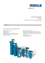
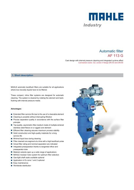
<strong>Automatic</strong> <strong>filter</strong><br />
<strong>AF</strong> <strong>113</strong> G<br />
Cast design with internal pressure cleaning and integrated cyclone effect<br />
Connection sizes: G2, screw in flange DN 50 and DN 65<br />
1. Short description<br />
LEER<br />
<strong>MAHLE</strong> automatic backflush <strong>filter</strong>s are suitable for all applications<br />
where low-viscosity liquids have to be <strong>filter</strong>ed.<br />
These compact, inline <strong>filter</strong> systems are designed for automatic<br />
cleaning. The system is cleaned by rotating the element and backflushing<br />
with internal pressure media.<br />
Advantages:<br />
Extended <strong>filter</strong> service life due to the use of a cleanable element<br />
Cleaning is possible without interrupting filtration<br />
Precise separation quality in accordance with the surface <strong>filter</strong><br />
principle<br />
Top-quality, asymmetric <strong>filter</strong> medium made of multiple-sintered<br />
stainless steel fleece on a rugged core element<br />
Efficient <strong>filter</strong> cleaning assures maximum process stability<br />
Solid construction and high-quality materials for a long<br />
service life<br />
Minimal liquid loss during cleaning<br />
Filter cleaned one segment at a time with a high backflush pulse<br />
Actual <strong>filter</strong> rating and nominal separation are indicated<br />
Integrated preseparation thanks to tangential inflow and<br />
preseparator tube<br />
Material variants open up a wide range of applications<br />
<strong>MAHLE</strong> modular Vario system for optimum <strong>filter</strong> selection<br />
Gas-tight shaft seals available optional<br />
Application in Ex zone 1 and 2 optional<br />
Easy maintenance<br />
Worldwide distribution
2. Operating principle<br />
The <strong>MAHLE</strong> <strong>AF</strong> <strong>113</strong> G backflush <strong>filter</strong> belongs to the Vario series.<br />
The compact <strong>MAHLE</strong> automatic <strong>filter</strong> system is used for fine and<br />
micro-filtration of a variety of low-viscosity liquids.<br />
This inline pressure <strong>filter</strong> consumes no <strong>filter</strong> material, which<br />
means there is also no need for subsequent disposal. The <strong>filter</strong><br />
is cleaned without interrupting operation. The concentrated solids<br />
are drained off simply by opening the system for a short time.<br />
The medium to be cleaned is guided into the <strong>filter</strong> housing<br />
under pressure and flows inward through the <strong>MAHLE</strong><br />
segmented element. Particles settle on the surface of the <strong>filter</strong><br />
medium. The <strong>filter</strong>ed fluid exits the <strong>filter</strong> housing at the top<br />
opposite the inlet connection.<br />
The <strong>filter</strong> is cleaned when a preset differential pressure limit, a set<br />
interval or a defined <strong>filter</strong>ed fluid quantity is reached. The<br />
segmented element is turned as the cleaning valve is opened. The<br />
segments are then guided one at a time past the flushing channel<br />
on the outer circumference,<br />
causing them to open and close alternately. The internal pressure<br />
is built up at a throttling point downstream of the <strong>filter</strong>, so that when<br />
one segment opens, an outward surge cleans the separated<br />
particles from the <strong>filter</strong> material. As a result of this pulse cleaning<br />
principle, the particles are catapulted out, collected in the flushing<br />
channel and discharged with a small amount of internal medium.<br />
One turn is sufficient to clean all segments. The residue that has<br />
settled in the collection cone can be emptied via the drain valve<br />
either when the machine is at a standstill or during filtration.<br />
The integrated preseparator relieves the load on the<br />
segmented element, particularly from coarse and heavy particles.<br />
This is achieved by a tangential flow around the preseparator tube<br />
and the deflection edges.<br />
All <strong>filter</strong>s of the <strong>MAHLE</strong> Vario series are protected by various<br />
patents.<br />
Used <strong>MAHLE</strong> <strong>filter</strong> elements in the <strong>AF</strong> <strong>113</strong> G backflush <strong>filter</strong>:<br />
<strong>MAHLE</strong> topmesh elements<br />
(standard):<br />
Good cleanability due to<br />
asymmetric design<br />
High effective <strong>filter</strong> surface<br />
Defined particle retention<br />
Several material combinations<br />
possible<br />
<strong>MAHLE</strong> notched wire elements:<br />
High differential pressure stability<br />
High wear resistance in extreme<br />
applications<br />
Good backflush properties<br />
Several material combinations<br />
possible<br />
1 Inlet connection<br />
2 Outer inlet plenum<br />
3 Preseparator tube<br />
4 Inner inlet plenum<br />
5 <strong>MAHLE</strong> segment element<br />
6 <strong>MAHLE</strong> <strong>filter</strong> materials<br />
7 Plenum for <strong>filter</strong>ed fluid<br />
8 Drain connection for <strong>filter</strong>ed fluid<br />
9 Residue collection cone<br />
10 Drain valve<br />
11 Drive motor<br />
12 Flushing channel<br />
13 P2-control throttle<br />
14 Cleaning valve<br />
15 P3-control throttle (not always required)<br />
16 Differential pressure contact gauge<br />
17 P1-gauge<br />
18 P2-gauge<br />
19 P3-gauge (not always required)<br />
<strong>AF</strong> <strong>113</strong> G 2
3. Technical data<br />
1 Cleaning drive: Worm<br />
gear motor can be mounted<br />
at each 90° position<br />
2 Lifting eyebolts<br />
3 Vent screw G¼<br />
4 P2 control throttle with P2<br />
gauge<br />
5 Optional: Differential<br />
pressure indicator/switch<br />
6 Mounting holes M12<br />
7 P1-Manometer<br />
8 Mounting holes M8<br />
9 Optional: <strong>Automatic</strong><br />
backflush valve<br />
10 Optional: P3 control throttle<br />
with<br />
P3 gauge<br />
11 Name-plate<br />
12 Optional: <strong>Automatic</strong> drain<br />
valve<br />
13 Clearance required =<br />
600 mm<br />
Filter data<br />
Motor data<br />
Max. operating pressure: 16 bar<br />
Max. operating<br />
temperature: 100 °C<br />
Materials: - Housing and cover:<br />
Nodular cast iron<br />
- Internals: Nodular cast iron, steel<br />
- Bearing bushes: PTFE based<br />
- Seals: FPM (Viton)<br />
- Segmented element: 1.4571 or<br />
1.4571/Al (∆p max. 10 bar)<br />
Cover lock:<br />
4 x M20 hexagon screws<br />
Optional: Ex protection<br />
acc. to ATEX 94/9/EG: - Electr. components in Ex II 2G T3<br />
- Mech. components in Ex II 2G c T3<br />
Connections and<br />
nominal diameters: - A-inlet, B-outlet, C-drain: G2<br />
- E-backflush: G1<br />
- F-gauge: G¼<br />
- G-indicator: G1/8<br />
- All threaded holes acc.<br />
to DIN 3852 X<br />
- Optional: A/B/C screw-in flanges<br />
DN 50 or DN 65 acc. to<br />
EN 1092-1/05A<br />
Drive shaft seal:<br />
Lip seal with O-ring<br />
External finish:<br />
Synthetic resin primer, blue acc.<br />
to RAL 5007<br />
Worm gear motor<br />
Multi-range winding<br />
V Hz kW U/min A<br />
230 ± 10% 50 0.18 9.3 1.2<br />
400 ± 10% 50 0.18 9.3 0.7<br />
266 ± 10% 60 0.22 11.2 1.1<br />
460 ± 10% 60 0.22 11.2 0.7<br />
Protection class: IP55; insulation class F; output torque: 52 Nm<br />
Optional:<br />
Worm gear motor Ex<br />
Ex II 2G T3, output torque 97 Nm<br />
Weigh: 85 kg<br />
Volume: 12 l<br />
Differential pressure resistance<br />
Segmented element with topmesh or stainless steel fleece: 10 bar<br />
Segmented element with triangular notched wire winding: 25 bar<br />
Other versions available on request!<br />
Technical data is subject to change without notice!<br />
<strong>AF</strong> <strong>113</strong> G 3
4. Design and application<br />
Element type<br />
(see section 6)<br />
Total surface<br />
in cm²<br />
Filter rating in µm/<br />
effective <strong>filter</strong> surface in cm²<br />
5 10 20 30 40 60 80 100 200<br />
<strong>AF</strong> 100XX6 763 637 637 637 637 637 637 637 637<br />
<strong>AF</strong> 120XX6 Effect. <strong>filter</strong> surface % 6 32 39 40 40 43 45 48<br />
Effect. <strong>filter</strong> surface<br />
cm²<br />
38 204 248 255 255 274 286 306<br />
Recommended design<br />
Cleaning and discharge modes<br />
Fully automatic operation:<br />
<strong>Filtration</strong> usually takes place under pressure. The <strong>filter</strong> is cleaned after a programmed time<br />
or a preset number of cycles or according to the differential pressure. We recommend<br />
cleaning the system at a differential pressure of approximately 0.5 - 0.7 bar. The cleaning<br />
motor is operated for around 7 seconds (about one turn of the element). The cleaning<br />
valve remains open for this period. An internal pressure of 2 - 3 bar is adequate to clean the<br />
<strong>filter</strong> efficiently.<br />
The drain valve is opened in order to discharge the <strong>filter</strong>. Depending on the residue<br />
concentration, this can either take place directly after cleaning or be time or cycle<br />
controlled. The opening time of the drain valve is 2 - 3 seconds.<br />
Refer to the Instruction Manual for further information.<br />
<strong>MAHLE</strong>´s team of specialists will be pleased to assist in any way. Tests can be carried out<br />
in the absence of reliable evaluation criteria.<br />
5. Performance curves<br />
The curves indicate the volume flow<br />
through the complete <strong>filter</strong> system (<strong>filter</strong><br />
housing including element) and are<br />
referred to a differential pressure of<br />
0.3 bar. Specific process information is<br />
essential to guarantee reliable operation<br />
of an automatic <strong>filter</strong>.<br />
Viscosity<br />
y = Volume flow V [l/min]<br />
x = Filter rating f [µm]<br />
mm²/s = cst<br />
<strong>AF</strong> <strong>113</strong> G 4
6. Type number key<br />
Type number key with selection example for <strong>AF</strong> <strong>113</strong>63-1321-41220/G3<br />
Size<br />
<strong>AF</strong> <strong>113</strong>6 1 x 110x265<br />
No. of steps x diameter x length [mm]<br />
Cleaning drive<br />
3 Gear motor 230/400 V, 50 Hz oder 266/460 V, 60 Hz<br />
4 Gear motor 230/400 V, 50 Hz Ex II 2G T3<br />
Inlet and outlet connections<br />
3 DN 50<br />
13 G2<br />
14 Screw-in flange DN 50 for cast design<br />
15 Screw-in flange DN 65 for cast design<br />
18 G2½<br />
Permissible operating pressure in bar (housing/cover)<br />
1 PN 10<br />
2 PN 16<br />
Material Seal FPM, PU, bearing PTFE<br />
1 Cover and housing nodular cast iron, internals steel, aluminium<br />
3 Cover and housing nodular cast iron, internals stainless steel 1.4301/1.4571<br />
Differential pressure indicator and gauge<br />
1 PiS 3076, switching level at 1.2 bar, static 63 bar, aluminium/FPM<br />
2 PiS 3076, switching level at 0.7 bar, static 63 bar, aluminium/FPM<br />
4 PiS 3170, digital ∆p gauge, 2 switching levels settable from 0 to 16 bar<br />
5 PiS 3175, digital ∆p gauge, 2 pressure transmitters settable from 0 to 16 bar<br />
Valves and control throttles<br />
1 P2 control throttle with P2 gauge<br />
6 Like 1 but with P3 control throttle and P3 gauge<br />
Drain valve<br />
2 Ball valve, electropneumatic 24 V DC<br />
3 Ball valve, electropneumatic 230 V AC<br />
4 Ball valve, electric 24 V DC<br />
5 Ball valve, electric 230 V AC<br />
Cleaning valve<br />
2 Ball valve, electropneumatic 24 V DC<br />
3 Ball valve, electropneumatic 230 V AC<br />
4 Ball valve, electric 24 V DC<br />
5 Ball valve, electric 230 V AC<br />
Optional features<br />
0 Without/special version<br />
.<br />
<strong>AF</strong> <strong>113</strong>6 3 - 13 2 1 -4 1 2 2 0 -XXXX (end number for special version)/G3<br />
.<br />
End number Special version<br />
3001 Standard <strong>filter</strong> insert (complete), without housing or drive<br />
3002 Standard <strong>filter</strong> insert (complete), without housing, with drive<br />
3700 PTFE seals<br />
Other numbers On request<br />
<strong>AF</strong> <strong>113</strong> G 5
Type number key with selection example for elements for <strong>AF</strong> 100, 120<br />
Series<br />
<strong>AF</strong> 100 Segmented element with topmesh (5 µm to 100 µm)<br />
<strong>AF</strong> 120 Segmented element with triangular notched wire winding (60 µm to 250 µm) - only <strong>AF</strong> 120206 version available<br />
Material Core element Filter medium Clamp rings Wire width in mm<br />
Segmented<br />
element<br />
17 Al 1.4571 St -<br />
20 Hardcoted Al 1.4571 1.4571 -<br />
21 1.4571 1.4571 1.4571 -<br />
Overall length Diameter x length in mm<br />
6 110x265<br />
Gap width/rating in µm (see 4. Design and application)<br />
003 30 µm 010 100 µm<br />
0005 5 µm 004 40 µm 013 130 µm<br />
001 10 µm 006 60 µm 016 160 µm<br />
002 20 µm 008 80 µm 025 250 µm<br />
Other <strong>filter</strong> ratings on request<br />
<strong>AF</strong> 100 17 6 - 006<br />
.<br />
For the correct choice of the <strong>filter</strong> fineness please consult the table on page 4.<br />
.<br />
7. Spare parts<br />
No. Designation Material no.<br />
FPM/C steel<br />
PTFE/VA<br />
1 Bush kit 70308169<br />
2 Set of seals<br />
70316068 70316071<br />
(complete)<br />
3 Backflush channel moulding 79744004 70312375<br />
4 Cartridge see name-plate<br />
LEER<br />
Please contact us for detailed technical information, any open questions about options, accessories and for general expert advice. Completion<br />
of the relevant questionnaire would facilitate in the coordination of all important parameters. Comprehensive documentation on our <strong>filter</strong> range,<br />
<strong>filter</strong> elements and accessories can be provided. About installation and operation, please refer to the Instruction Manual.<br />
LEER<br />
LEER<br />
LEER<br />
LEER<br />
LEER<br />
LEER<br />
LEER<br />
LEER<br />
LEER<br />
LEER<br />
LEER<br />
LEER<br />
LEER<br />
LEER<br />
LEER<br />
LEER<br />
<strong>MAHLE</strong> Industriefiltration GmbH<br />
Schleifbachweg 45<br />
D-74613 Öhringen<br />
Phone +49 7941 67-0<br />
Fax +49 7941 67-23429<br />
industrialfiltration@mahle.com<br />
www.mahle-industry.com<br />
79799073.12/2013<br />
<strong>AF</strong> <strong>113</strong> G 6